Valvetrain BMW 318i 1992 E36 Workshop Manual
[x] Cancel search | Manufacturer: BMW, Model Year: 1992, Model line: 318i, Model: BMW 318i 1992 E36Pages: 759
Page 3 of 759
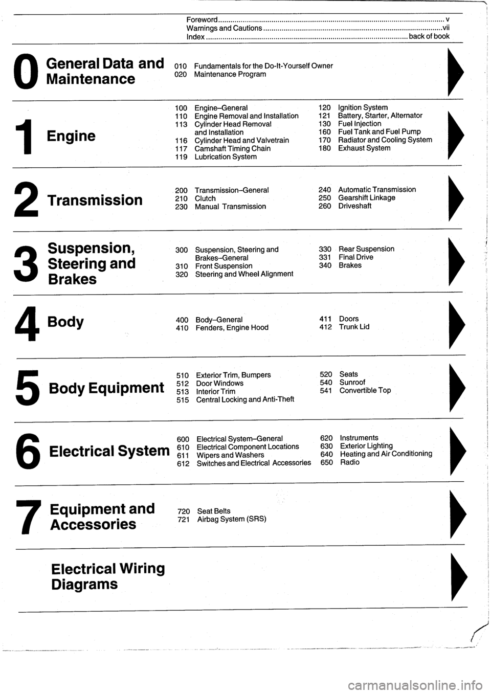
General
Data
and
010
FundamentalsfortheDo-lt-YourselfOwner
Maintenance
020
Maintenance
Program
Engine
Transmission
Suspension,
Steering
and
Brakes
4
Body
100
Engine-General
110
Engine
Removal
and
Installation
113
Cylinder
Head
Removal
and
Installation
116
Cylinder
Head
and
Valvetrain
117
Camshaft
Timing
Chain
119
Lubrication
System
200
Transmission-General
210
Clutch
230
Manual
Transmission
510
Exterior
Trim,
Bumpers
520
Seats
Bo
y
Equipment
512
DoorWTdws
540
nr
t
513
InteriorTrim
541
Convertible
Top
515
Central
Locking
and
Anti-Theft
600
Electrical
System-General
620
Instruments
Electrical
S
stem
610
Electrical
Component
Locations
630
Exterior
Lighting
611
Wipers
and
Washers
640
Heating
and
Air
Conditioning
6
612
Switches
and
Electrical
Accessories
650
Radio
Equipment
and
720
SeatBelts
Accessories
721
Airbag
System
(SRS)
Electrical
Wiring
Diagrams
Foreword
.
...
.
.
.
..................
.
.
.
.....
.
............
.
...
.
.
.
.
.
................
.
.
.
.....
.
......
.
................
.
.
.
.....
v
Warnings
and
Cautions
.....
.
...
.
.
.
.
.
..........
.
...
.
.
.
.
.
......
.
.........
.
.
.
...
.
.
.
......
.
.
.
.
.
............
.
.
.
.
.
.
.vii
Index
..............
.
.
.
.....
.
............
.
...
.
.
.
.
.
........
.
...
.
.
.
.
.
.......
.
......
.
...
.
.
.
.
.
.
.
........
.
.
.
..
back
of
book
300
Suspension,
Steering
and
330
RearSuspension
Brakes-General
331
Final
Drive
310
Front
Suspension
340
Brakes
320
Steering
and
Wheel
Alignment
400
Body-General
411
Doors
410
Fenders,
Engine
Hood
412
Trunk
Lid
120
Ignition
System
121
Battery,Starter,
Alternator
130
Fue¡
Injection
160
Fuel
Tank
and
Fuel
Pump
170
Radiator
and
Cooling
System180
Exhaust
System
240
Automatic
Transmission
250
Gearshift
Linkage
260
Driveshaft
Page 42 of 759
020-20
MAINTENANCE
PROGRAM
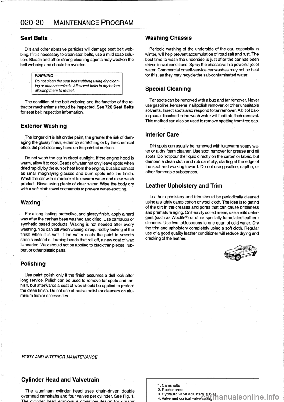
Seat
Belts
Washing
Chassis
Dirt
and
other
abrasive
particles
will
damage
seat
belt
web-
Periodic
washing
of
the
underside
of
the
car,
especially
in
bing
.
If¡t
is
necessary
to
clean
seat
belts,
use
a
mild
soap
solu-
winter,
will
help
prevent
accumulation
of
road
salt
and
rust
.
The
tion
.
Bleach
and
other
strong
cleaning
agents
may
weaken
the
besttime
to
wash
the
underside
is
just
after
the
car
has
been
belt
webbing
and
should
be
avoided
.
driven
in
wet
conditions
.
Spray
the
chassis
with
a
powerful
jet
of
water
.
Commercial
or
self-service
car
washes
may
not
be
best
WARNING-
for
this,
as
they
may
recycle
the
salt-contaminated
water
.
Do
not
clean
the
seat
belt
webbing
using
dry
clean-
ing
or
other
chemicals
.
Allow
wet
belts
to
dry
before
allowing
them
to
retract
.
Speeial
Cleaning
The
condition
of
the
belt
webbing
and
the
function
of
the
re-
tractor
mechanisms
should
be
inspected
.
See720
Seat
Belts
for
seat
belt
inspection
information
.
Exterior
Washing
The
longer
dirt
isleft
on
the
paint,
the
greater
the
risk
of
dam-
aging
the
glossy
finish,
either
by
scratching
or
by
the
chemical
effect
dirt
particles
may
have
on
the
paintedsurface
.
Do
not
wash
the
car
in
direct
sunlight
.
If
the
engine
hood
is
warm,
allow
it
to
cool
.
Beads
of
water
not
only
leavespots
when
dried
rapidly
by
the
sun
or
heat
from
the
engine,
but
also
can
act
as
small
magnifyingglasses
and
burn
spots
into
the
finish
.
Wash
thecar
with
a
mixture
of
lukewarmwater
and
a
car
wash
product
.
Rinse
using
plenty
of
clear
water
.
Wipe
the
body
dry
witha
soft
cloth
towel
or
chamois
to
prevent
water-spotting
.
Waxing
For
a
long-lasting,protective,
and
glossy
finish,
apply
a
hard
wax
after
thecar
has
been
washed
and
dried
.
Use
carnauba
or
synthetic
based
products
.
Waxing
is
not
needed
after
every
washing
.
You
can
tell
when
waxing
is
required
by
looking
at
the
finísh
when
it
is
wet
.
If
the
water
coats
the
paint
in
smooth
sheets
instead
of
forming
beads
that
rol¡
off,
a
new
coat
of
wax
is
needed
.
Wax
shouldnot
be
applied
to
black
trim
pieces,
rub-
ber,or
other
plastic
parts
.
Polishing
Use
paintpolish
only
if
the
finish
assumes
a
dull
lock
after
long
service
.
Polish
can
beused
to
remove
tar
spots
and
tar-
nish,
but
afterwards
a
coat
of
wax
should
be
applied
to
protect
the
clean
finish
.
Do
not
use
abrasive
polish
or
cleaners
on
alu-
minum
trimor
accessories
.
BODYAND
INTERIOR
MAINTENANCE
Cylinder
Head
and
Valvetrain
The
aluminum
cylinder
head
uses
chain-driven
double
overhead
camshafts
and
four
valves
per
cylinder
.
See
Fig
.
1
.
Tha
rvfinriar
hand
nmnlnve
n
ernceflnier
rineinn
fnr
nronter
Tar
spots
canbe
removed
with
a
bugand
tar
remover
.
Never
use
gasoline,
kerosene,
nail
polish
remover,
or
other
unsuitable
solvents
.
Insect
spots
also
respond
to
tar
remover
.
A
bit
of
bak-
ing
soda
dissolved
in
the
wash
water
will
facilitate
their
removal
.
This
method
can
also
beused
to
remove
spotting
from
tree
sap
.
Interior
Care
Dirt
spots
can
usually
be
removed
with
lukewarm
soapy
wa-
ter
or
a
dry
foam
cleaner
.
Use
spot
remover
for
grease
and
o¡I
spots
.
Do
not
pour
the
(quid
directly
on
the
carpetor
fabric,
but
dampen
a
clean
cloth
and
rub
carefully,starting
at
the
edge
of
the
spot
and
working
inward
.
Do
not
use
gasoline,
naptha,
or
other
flammable
substances
.
Leather
Upholstery
and
Trim
Leather
upholstery
and
trim
should
be
periodically
cleaned
using
a
slightly
damp
cotton
or
wool
cloth
.
The
idea
is
to
get
rid
of
the
dirtin
the
creases
and
pores
that
can
cause
brittleness
and
premature
aging
.
On
heavily
soiled
areas,
usea
mild
deter-
gent
(such
as
Woolite®)
or
other
specially
formulated
leather
r
cleaners
.
Use
two
tablespoons
to
one
quart
of
cold
water
.
Dry
the
trim
and
upholstery
completely
using
a
soft
cloth
.
Regular
use
of
agood
quality
leather
conditioner
will
reduce
drying
and
crackingof
the
leather
.
1
.
Camshafts
2
.
Rocker
arms
3
.
Hydraulic
valve
adjusters
(HVA)
4
.
Valve
and
conical
valve
spring
Page 43 of 759
GENERAL
.
.....
.
.
.
.
.
.
.
...
.
.
.
.
.
.
.
.
.
...
100-1
Cylinder
Block
and
Crankshaft
.
.
.
.
.
.
.
.
.
...
100-1
Connecting
Rods
and
Pistons
.
.
.
.
.
.
.
.
.
.
.
.
.
100-1
Cylinder
Head
and
Valvetrain
.
.
.
.
.
.
.
.
.
.
.
.
.
100-2
VANOS
(Variable
Valve
Timing)
.
.
.
.
.
.
.
.
...
100-2
DISA
(Dual
Resonance
Intake
System)
.
.
.
.
.
100-3
Engine
Management
System
.
.
.
.
.
.
.
.
.
.
.
.
.
100-3
Ignition
......
.
.
.
.........
.
.
.
.
.
.
.
.
.
.
.
.
100-5
Fuel
Delivery
..
.
.
.
.....
.
...
.
.
.
.
.
.
.
.
.
.
.
.
100-5
Cooling
System
.
...........
.
.
.
.
.
.....
.
.
100-5
Lubrication
System
.........
.
.
.
.
.
.
.
.
.
.
.
.
100-5
MECHANICALTROUBLESHOOTING
.
.
.
.
100-5
Warnings
and
Cautions
..
.
...
.
.
.
.
.
.
.
.
.
.
.
.
100-5
Cylinder
compression,
checking
.
.
.
.
.
.
.
.
.
.
.
100-6
EngineMechanical
Troubleshooting
Table
.
.
.
100-7
DRIVEABILITY
TROUBLESHOOTING
...
100-8
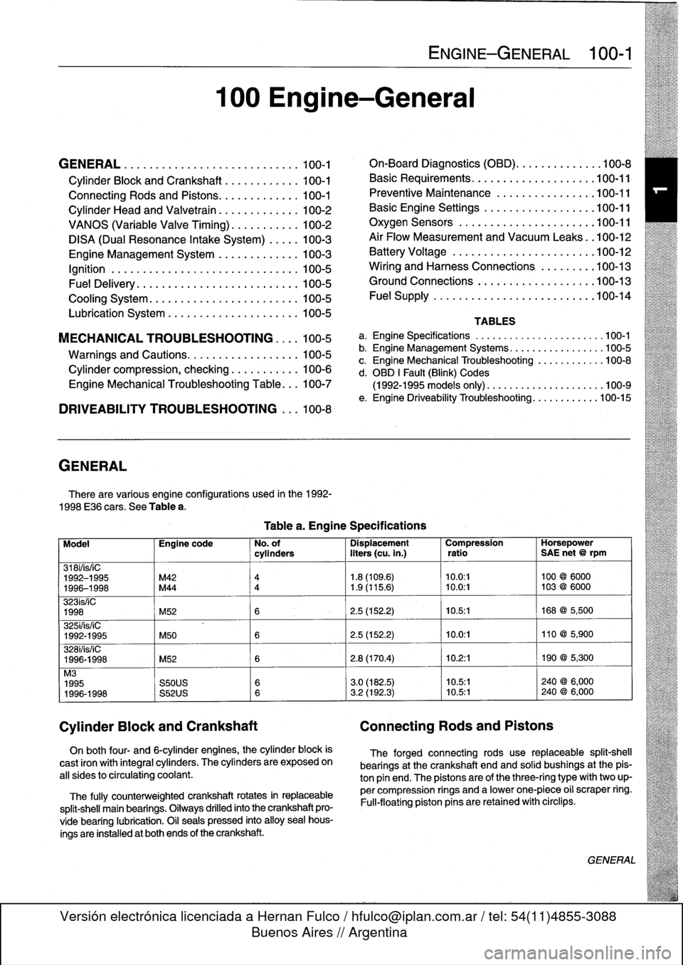
GENERAL
There
are
various
engíne
configurations
used
in
the
1992-
1998
E36
cars
.
See
Table
a
.
On
both
four-
and
6-cylinder
engines,
the
cylinder
block
is
cast
¡ron
with
integral
cyiinders
.
The
cyiinders
are
exposed
on
all
sides
to
circulating
coolant
.
The
fully
counterweighted
crankshaft
rotates
in
replaceable
split-shell
main
bearings
.
Oiiways
drilled
into
the
crankshaft
pro-
vide
bearing
lubrication
.
O¡I
seals
pressed
into
alloy
sea¡
hous-
ings
are
installedat
both
ends
of
the
crankshaft
.
100
Engine-General
Tablea
.
Engine
Specifications
ENGINE-GENERAL
100-1
On-Board
Diagnostics
(OBD)
...
.
.
.
.
.
.
.
.
.
.
.
100-8
Basic
Requirements
....
.
.
.
...
.
.
.
.
.
....
.100-11
Preventive
Maintenance
......
.
.
.
.
.
.....
100-11
Basic
Engine
Settings
..
.
.....
.
.
.
.
.
.....
100-11
Oxygen
Sensors
.
.
.
...
.
.
.
...
.
.
.
.
.
....
.100-11
Air
Flow
Measurement
and
Vacuum
Leaks
.
.100-12
Battery
Voltage
.
.
...........
.
.
.
.
.
.....
100-12
Wiring
and
Harness
Connections
.
.
.
.
.....
100-13
Ground
Connections
...
.
.....
.
.
.
.
.
.....
100-13
Fue¡
Supply
....
.
...........
.
.
..
.....
.100-14
TABLES
a
.
Engine
Specifications
...
...
...........
.
..
..
.100-1
b
.
Engine
Management
Systems
..
..
...........
..
100-5
c
.
Engine
Mechanical
Troubleshooting
..........
.
.
100-8
d
.
OBD
1
Fault
(Blink)
Codes
(1992-1995
models
only)
.
...
..
..
..........
..
.100-9
e
.
Engine
Driveability
Troubleshooting
...........
.100-15
Model
Engine
code
No
.
of
Dispiacement
Compression
Horsepower
cyiinders
liters
(cu
.
in
.)
ratio
SAE
net
@
rpm
318i/is/¡C
1992-1995
M42
4
1
.8
(109
.6)
10
.0
:1
100
@
6000
1996-1998
M44
4
1
.9
(115
.6)
~
10
.0
:1
103
@
6000
323ís/iC
1998
M52
6
2
.5
(152
.2)
10
.5
:1
168
@
5,500
325i/is/iC
1992-1995
M50
6
2
.5
(152
.2)
10
.0
:1
110
@
5,900
328i/is/iC
1996-1998
M52
6
2
.8
(170
.4)
10
.2
:1
190
@
5,300
M3
1995
S50US
6
3
.0
(182
.5)
10
.5:1
240
@
6,000
1996-1998
S52US
6
3
.2
(192
.3)
10
.5:1
240
@
6,000
Cylinder
Block
and
Crankshaft
Connecting
Rods
and
Pistons
The
forged
connecting
rods
use
replaceable
split-shell
bearings
at
the
crankshaft
endand
solid
bushings
at
the
pis-
ton
pin
end
.
The
pistonsare
of
the
three-ring
typewith
two
up-
per
compression
rings
and
a
lowerone-piece
o¡i
scraper
ring
.
Fui¡-floating
piston
pins
are
retained
with
circlips
.
GENERAL
Page 44 of 759
100-2
ENGINE-GENERAL
Cylinder
Head
and
Valvetrain
The
aluminum
cylinder
head
uses
chain-driven
double
overhead
camshafts
and
four
valves
per
cylinder
.
See
Fig
.
1
.
The
cylinder
head
employs
a
crossflow
design
for
greater
power
and
efficiency
.
Intake
air
enters
the
combustion
cham-
ber
from
one
side
while
exhaust
gasses
exit
from
the
other
.
Oílways
in
the
head
provide
lubrication
for
the
camshafts)
and
valvetrain
.
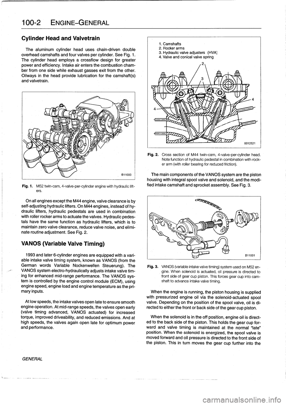
Fig
.
1
.
M52
twin-cam,
4-valve-per-cylinder
engine
with
hydraulíc
lift-
ers
.
On
all
engines
exceptthe
M44
engine,
valveclearance
is
by
seif-adjusting
hydraulic
lifters
.
On
M44
engines,
instead
of
hy-
draulic
lifters,
hydraulic
pedestaisare
used
in
combination
with
roller
rocker
arms
to
actuate
the
valves
.
Hydraulic
pedes-
tals
have
the
same
function
as
hydraulic
lifters,
which
ís
to
maintain
zero
valve
clearance,
reduce
valve
noise,
and
elimí-
nate
routíne
adjustment
.
See
Fig
.
2
.
VANOS
(Variable
Valve
Timing)
GENERAL
1
.
Camshafts
2
.
Rocker
arms
3
.
Hydraulic
valve
adjusters
(HVA)
4
.
Valve
and
conical
valve
spring
4
Fig
.
2
.
Cross
sectionof
M44
twin-cam,
4-valve-per-cylinder
head
.
Note
function
of
hydraulíc
pedestal
in
combination
with
rock-er
arm
(with
roller
bearing
for
reduced
friction)
.
The
main
components
of
the
VANOS
system
arethe
piston
housing
with
integral
spool
valve
and
solenoid,
and
the
modi-
fied
intake
camshaft
and
sprocket
assembly
.
See
Fig
.
3
.
1993
and
later
6-cylinder
engines
are
equipped
with
a
vari-
B11001
able
intake
valve
timing
system,
known
as
VANOS
(from
the
German
words
Variable
Nockenwellen
Steuerung)
.
The
Fig
.
3
.
VANOS
(variable
intake
valve
timing)
systemusedon
M52
en-
VANOS
system
electro-hydraulically
adjusts
intake
valve
tim-
gine
.
When
solenoid
is
actuated,
oíl
pressure
is
directed
to
ingfor
enhanced
mid-range
performance
.
The
VANOS
sys-
front
side
of
gear
cup
piston
.
This
forces
gear
cup
finto
camtem
is
controlled
by
the
engine
control
module
(ECM),
using
shaft
to
advance
intake
valve
timing
.
enginespeed,engine
load
and
engine
temperature
asthe
pri-
mary
inputs
.
When
the
engine
is
running,
the
piston
housing
is
supplied
with
pressurized
engine
oil
víathe
solenoid-actuatedspool
At
low
speeds,
the
intake
valves
open
late
to
ensure
smooth
valve
.
Depending
on
the
position
of
the
spool
valve,
oil
isdi
engine
operation
.
At
mid-rangespeeds,
thevalves
open
early
rected
to
either
the
front
or
back
side
of
the
gear
cup
piston
.
(valvetiming
advanced,
VANOS
actuated)
for
increased
torque,
improved
driveability,
and
reduced
emissions
.
And
at
When
the
solenoid
isin
the
off
position,
engine
oíl
is
direct-
high
speeds,
the
valves
again
open
late
for
optimum
power
ed
to
the
back
side
of
the
piston
.
This
holds
the
gear
cup
for-
and
performance
.
ward
and
valve
timing
is
maintained
at
the
normal
"late"
position
.
When
the
solenoid
is
energized,
the
spoolvalve
is
moved
forward
and
oil
pressure
is
directed
to
the
front
side
of
the
piston
.
This
in
turn
moves
thegear
cup
further
into
the
Page 67 of 759
113
Cylinder
Head
Removal
and
Installation
GENERAL
.
...............
.
.
.
.
.
.......
113-1
CYLINDER
HEAD,
6-CYLINDER
.
.
.
.
.
.
.
113-10
Cylinder
head,
removing
(6-cylinder
engine)
..
113-10
CYLINDER
HEAD,
4-CYLINDER
..
.
...
.
.
113-1
Cylinder
head,
installing
(6-cylinder
engine)
...
113-15
Cylinder
head,
removing
(4-cylinder
engine)
...
113-1
E
Cylinder
head,
installing
(4-cylinder
engine)
...
113-6
GENERAL
CYLINDER
HEAD,
4-CYLINDER
The
information
given
inthis
repair
group
assumes
that
the
engine
is
installed
in
the
engine
bay
.
For
cylinder
head,
cam-
Cylinder
head,
removing
shaft,
and
valvetrain
disassembly
and
reconditioning
informa-
(4-cylinder
engine)
tion,
see116
Cylinder
Head
and
Valvetrain
.
For
ease
of
use
this
removal
procedure
is
broken
into
sub-
In
the
procedures
given
below,
engines
are
referred
to
by
sections,
as
follows
:
engine
code
.
If
necessary,
see100
Engine-General
for
en-
gine
code
and
application
information
.
NOTE-
If
a
head
gasket
problem
is
suspected,
acompression
test
will
usually
detectthe
fault
.
See
100
Engine-Gen-
eral
for
compression
testing
information
.
Special
BMW
service
tools
are
required
to
properly
remove
and
install
the
cylinder
head
on
both
the
4-cylinder
and
6-cyl-
inder
engines
.
The
special
tools
are
used
to
time
the
val-
vetrain
to
the
crankshaft
and
to
remove
the
Torx
(El
2)
head
bolts
.
Read
the
procedure
through
before
beginning
thejob
.
Cover
al¡
painted
surfaces
before
beginning
the
removal
procedure
.
As
an
aid
to
installation,
label
all
components,
wires,
and
hoses
before
removing
them
.
Do
not
reuse
gas-
kets,
O-rings
or
seals
during
reassembly
.
WARNING
-
Due
to
risk
of
personal
injury,
be
sure
the
engine
is
cold
before
beginning
the
removalprocedure
.
CYLINDER
HEAD
REMOVAL
AND
INSTALLATION
113-1
General
Coolingsystem,
draining
Cylinder
head
cover,
removing
Intake
manifold,
removing
Timing
chains,
uncoupling
Cylinder
head
assembly,
removing
WARNING
-
Allow
engine
to
cool
before
beginning
this
proce-
dure
.
General
1
.
Disconnect
negative
(-)
cable
from
battery
.
CAUTION
-
"
Prior
to
disconnectiog
the
battery,
read
the
bat-
tery
disconnection
cautions
given
at
the
front
of
this
manual
on
page
viii
.
"
Disconnecting
the
battery
may
erase
fault
codees)
stored
in
control
module
memory
.
Check
for
fault
codes
using
special
BMW
diagnostic
equipment
.
NOTE-
The
battery
is
mounted
in
the
luggage
compartment
behind
the
right
side
trim
panel
.
2
.
Working
underneath
vehicle,
remove
front
exhaust
pipe
from
exhaust
manifold
.
See
Fig
.
1
.
3
.
Disconnect
vacuum
hose
fitting
from
brake
booster
on
rear
bulkhead
.
Plug
opening
in
booster
and
hose
end
.
CYLINDER
HEAD,
4-CYLINDER
Page 85 of 759
GENERAL
CYLINDER
HEAD,
DISASSEMBLY
AND
ASSEMBLY
CYLINDER
HEAD
AND
VALVETRAIN
116-1
116
Cylinder
Head
and
Valvetrai
n
GENERAL
.
.....
.
.
.
...
.
.
.
.
.
.
.
.
.
.......
116-1
Hydraulic
cam
followers,
checking
and
replacing
(M42
and
al¡
6-cylinder
engines)
.
...
.....
.
..
116-9
CYLINDER
HEAD,
Valve
guides
.
.
.
...
.
.
.
.
.
.
...
.
.
.
.
.
.
.
.
.
.
116-10
DISASSEMBLY
AND
ASSEMBLY
...
.
...
116-1
Valves
.
.
.
.
.
.
.
.
.
.
.
.
.
...
.
...
.
.
.
.
.
...
.
.
116-11
Camshafts,
removing
and
installing
(M42
engine)
....
.
....
.
.
.
.
.
.
.
.
.
.....
.
.
116-1
Valves,
leak
test
.
.
.
.
.
.
.
.
.
.
...
.
.
.
.
.
.
.
.
.
.
116-11
Camshafts,
removing
and
installing
Valve
stem
oil
seals
.
.
.
.......
.
.
.
.
.
...
.
.
116-11
(M44
engine)
.........
.
.
.
.
.
.
.
.
.
.......
116-3
Valve
seats
.
.
.
.
.
.
.
.
.
...
.
...
.
.
.
.
.
...
.
.116-12
Camshafts,
removing
and
installing
Valve
springs
.
.
.
.
.
.
.
.
...
.
...
.
.
.
.
.
.....
116-12
(6-cylinder
engine)
.....
.
.
.
.
.
.
.
.
.
.......
116-4
Valves,
removing
and
installing
........
.
....
116-6
TABLES
CYLINDER
HEAD
AND
VALVETRAIN,
a
.
Cylinder
Head
Height
........
....
.
..
..........
116-7
RECONDITIONING
.
...
.
.
.
.
.
.
.
.
.
.......
116-7
b
.
Camshaft
Specifications
.......
..
.
..
........
.116-7
Cylinder
head
...
.
.
.
...
.
.
.
.
.
.
.
.
.
....
.
..
116-7
c
.
Valve
Guide
Specifications
....
...
.
..
........
116-10
d
.
Valve
Specifications
...........
..
.
..
........
116-11
Camshaft
.
.
.
.
.
.
.
.
.
.
.
.
.
.
...
.
.
.
.
.
.......
116-7
e
.
Valve
Seat
Dimensions
.........
.
..
..
......
.116-12
Hydraulic
valve
adjusters,
checking
and
replacing
(M44
engine)
..
.
.
.
116-8
Camshafts,
removing
and
installing
(M42
engine)
This
repair
group
covers
cylinder
head
and
valvetrain
ser-
vice
and
repair
.
Most
of
the
repairs
described
here
require
that
The
camshafts
can
be
removed
with
the
cylinder
head
the
cylinder
head
first
be
removed
as
described
in
113
Cylin-
mounted
on
the
engine
.
The
first
step
is
to
remove
the
cylinder
der
HeadRemoval
and
Installation
.
head
cover
.
See
113
Cylinder
HeadRemoval
and
Installa-
tion
.
NOTE-
Special
BMW
service
tools
should
always
be
used
to
remove
"
For
timing
chain
and
VANOS
repair
information,
see
and
install
the
camshafts
.
Removal
and
installation
of
the
cam-
117
Camshaft
Timing
Chain
.
shafts
without
the
special
tools
can
result
in
camshaft
and
valve
"
If
it
is
determined
that
the
cylinder
head
will
require
train
damage
.
significant
reconditioning
work,
a
remanufactured
cyl-
inder
head
may
bea
good
alternative
.
Remanufac-
WARNING-
tured
cylinder
heads
are
available
froman
authorized
The
process
of
evenly
loosening
the
camshaftbear
BMW
dealer
.
ing
cap
nuts
is
NOT
an
acceptable
method
of
re-
moving
the
camshafts
.
Be
sure
to
read
the
The
information
given
in
this
repair
group
is
organized
ac-
procedure
through
before
starting
the¡ob
.
cording
to
engine
code
.
For
engine
applicationinformation,
see100
Engine-General
.
1
.
Disconnect
negative
(-)
battery
cable
.
CAUTION-
Prior
to
disconnectiog
the
battery,
read
the
battery
disconnection
cautions
given
at
the
front
of
this
manualonpage
viii
.
BMW
special
tools
are
required
for
most
cylinder
head
ser-
2
.
Remove
radiator
cooling
fan
shroud
and
cooling
fan
.
vice
described
in
this
repair
group
.
Many
of
these
tools
areex-
See
170
Radiator
and
Cooling
System
.
pensive
and
only
available
through
an
authorized
BMW
dealer
.
If
the
special
tools
are
not
available,
one
altematve
is
to
remove
the
cylinder
head
and
have
it
disassembled
byan
authorized
CAUTION-
BMW
dealer
.
Be
sure
to
read
each
procedure
thoroughlybefore
Radiator
fa
n
has
left
hand
threads
.
starting
a
job
to
determinewhich
special
tools
and
equipment
will
be
necessary
.
CYLINDER
HEAD,
DISASSEMBLYANDASSEMBLY
Page 86 of 759
116-2
CYLINDER
HEADAND
VALVETRAIN
3
.
Remove
timing
chain
sprockets
and
timing
chains
from
7
.
Slowly
release
pressure
oncamshaft
bearing
capsby
camshafts
.
Remove
upper
timing
chain
guidefrom
cyl-
turningeccentric
shaft
.
Remove
bearing
caps
and
inder
head
.
See117
Camshaft
Timing
Chain
.
camshaft
.
Repeat
procedureon
remaining
camshaft
.
NOTE-
It
is
not
necessary
lo
remove
the
lower
timing
chain
cover
.
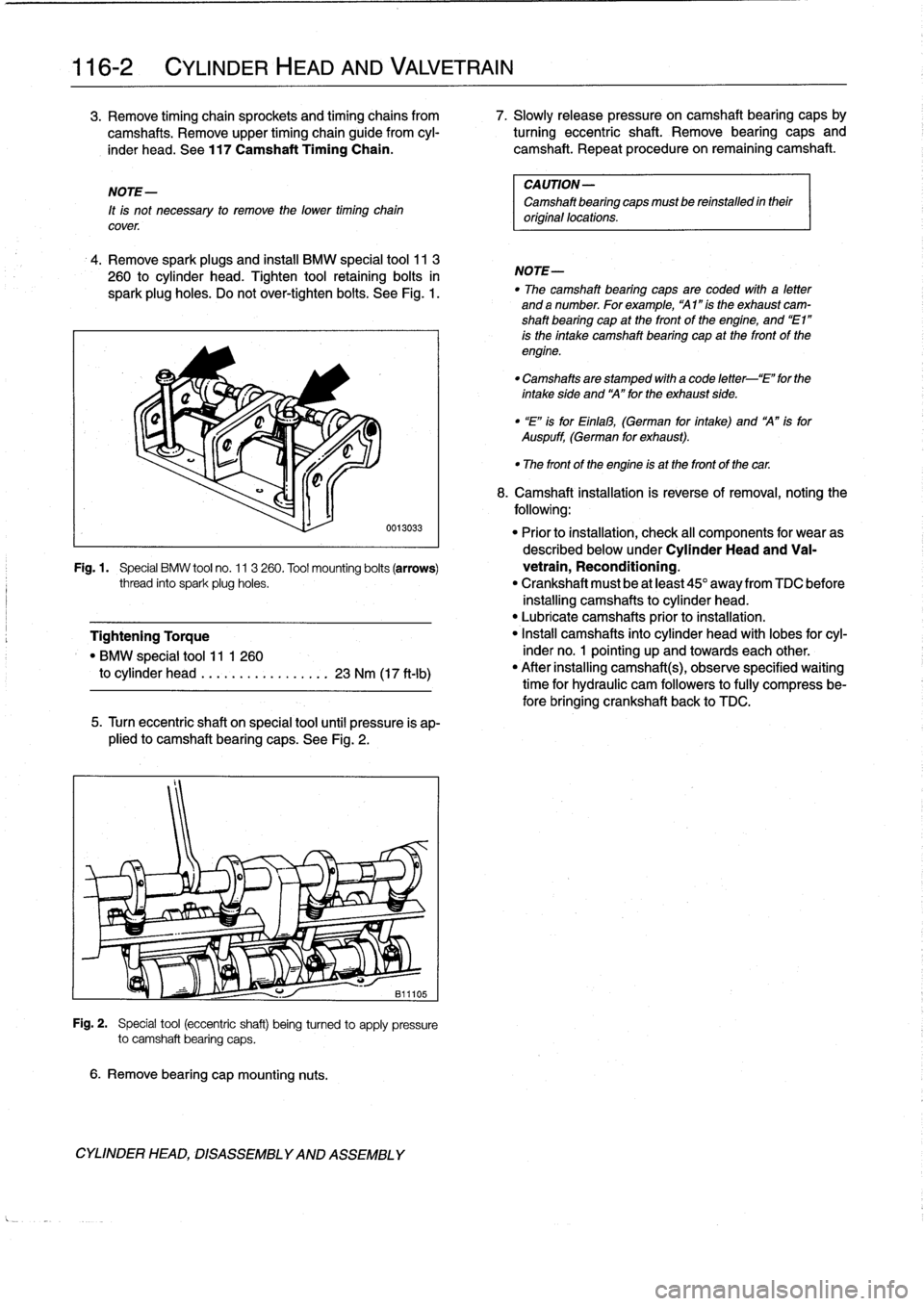
4
.
Remove
spark
plugs
and
instaf
BMW
special
tool
11
3
260
to
cylinder
head
.
Tighten
tool
retaining
bolts
in
spark
plug
holes
.
Do
not
over-tighten
bolts
.
See
Fig
.
1
.
6
.
Remove
bearing
cap
mounting
nuts
.
0013033
5
.
Turn
eccentric
shaft
on
special
tool
until
pressure
is
ap-
plied
to
camshaft
bearing
caps
.
See
Fig
.
2
.
Fig
.
2
.
Special
tool
(eccentric
shaft)
being
turned
to
apply
pressure
to
camshaft
bearing
caps
.
CYLINDER
HEAD,
DISASSEMBLYAND
ASSEMBLY
CAUTION-
Camshaft
bearing
caps
mustbe
reinstalled
intheir
original
locations
.
NOTE-
"
The
camshaft
bearing
caps
are
coded
wíth
a
letter
anda
number
.
Forexample,
"Al
"ís
the
exhaust
cam-
shaft
bearing
cap
at
the
front
of
the
engíne,
and
"El"
is
the
intake
camshaft
bearing
cap
at
the
front
of
the
engine
.
"
Camshafts
are
stamped
with
a
code
letter-`E"
for
the
intakeside
and
`A"forthe
exhaust
side
.
"
"E"
isforEinlal3,
(German
for
íntake)
and
A"
isfor
Auspuff,
(German
for
exhaust)
.
"
The
front
of
the
engine
is
at
the
front
of
thecar
.
8
.
Camshaft
installation
is
reverse
of
removal,noting
the
following
:
"
Prior
to
installation,
check
al¡
components
for
wear
as
described
below
underCylinder
Head
and
Va¡-
Fig
.1
.
Special
BMW
tool
no
.
11
3
260
.
Tool
mounting
bolts
(arrows)
vetrain,
Reconditioning
.
thread
into
spark
plug
holes
.
"
Crankshaft
must
be
at
least
45°
away
from
TDC
before
installing
camshafts
to
cylinder
head
.
"
Lubricate
camshafts
prior
to
installation
.
Tightening
Torque
"
Install
camshafts
into
cylinder
head
with
lobes
for
cyl-
"
BMW
special
tool
11
1
260
inder
no
.
1
pointing
up
and
towards
each
other
.
to
cylinder
head
.
...
.
.
...........
23
Nm
(17
ft-Ib)
"
After
installing
camshafts),observe
specified
waiting
time
for
hydraulic
cam
followers
to
fully
compress
be-
fore
bringing
crankshaft
back
to
TDC
.
Page 87 of 759
Camshaft
installation
waíting
times
"
Ator
above
68°F
(20°C)
............
.
..
10
minutes
"
50-68°F
(10-20°C)
................
..
.
30
minutes
"
32-50°F
(0-10°C)
.
.......
.
.........
..
.
75minutes
"
Reinstall
timing
chain
sprockets
and
tensioner
as
spe-
cifically
described
in
117
Camshaft
Timing
Chain
.
i
"
Wait
at
least
10minutes
before
cranking
engine
over
with
starter
motor
for
the
fi+
1
1/
/~~
.0
time
.
Tightening
Torques
"
Camshaft
bearing
caps
to
cylinder
head
(M7)
.............
15
Nm
(11
ft-Ib)
"
Cylinder
head
cover
to
cylinder
head
(M6)
.............
10
Nm
(89
in-lb)
"
Primary
timing
chain
tensioner
plug
to
cylinder
head
..
..
..
...........
40
Nm
(30
ft-Ib)
(see
117
Camshaft
Timing
Chain)
"
Spark
plugs
(M12)
..
.
.............
23
Nm
(17
ft-Ib
"
Timing
chain
cover
(upper)
to
cylinder
head
..
.
.
...
..........
10
Nm
(89
in-lb)
"
Timing
chainsprockets
to
camshaft
M6
........
.
...
.
..
.
..........
10
Nm
(7.5
ft-Ib)
M7
............
.
..
..
...........
15
Nm
(11
ft
.lb)
(see
117
Camshaft
Timing
Chain)
Camshafts,
removing
and
installing
(M44
engine)
Special
BMW
service
tools
should
always
be
used
to
remove
and
install
the
camshafts
.
Removal
and
installation
of
the
cam-
shafts
without
the
special
tools
can
result
in
camshaft
and
val-
vetrain
damage
.
1.
Disconnect
negative
(-)
battery
cable
.
CAUTION-
Prior
to
disconnecting
the
battery,
read
the
battery
disconnection
cautions
given
at
the
front
of
this
manual
on
page
vi¡¡
.
CYLINDER
HEAD
AND
VALVETRAIN
116-
3
2
.
Remove
spark
plugs
.
See
1201gnition
System
.
3
.
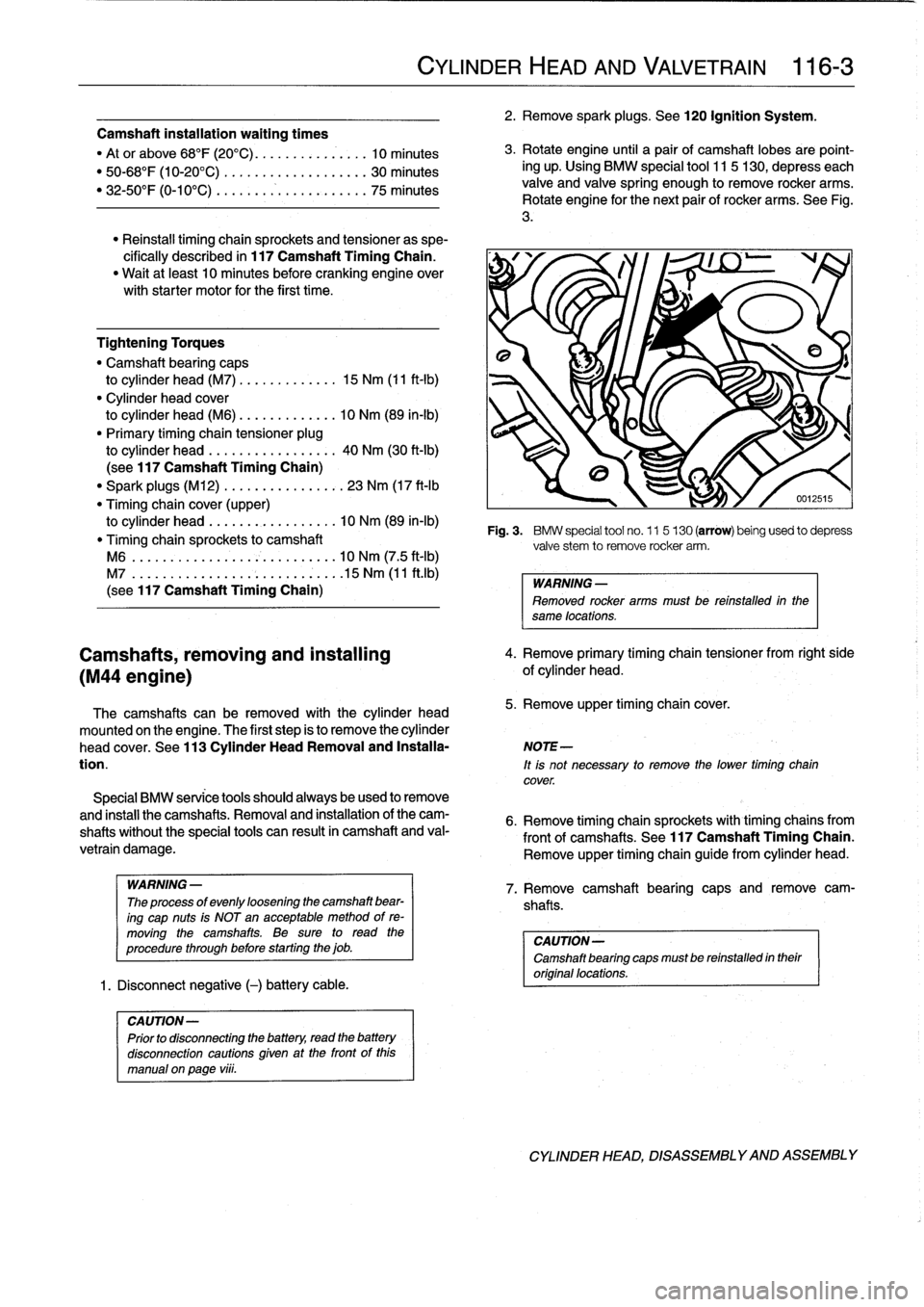
Rotateengine
until
a
pair
of
camshaft
lobes
are
point-
ing
up
.
Using
BMW
special
tool
115
130,
depresseach
valve
and
valve
spring
enough
to
remove
rocker
arms
.
Rotate
engine
for
the
next
pair
of
rocker
arms
.
See
Fig
.
3
.
cover
.
Fig
.
3
.
BMW
special
tool
no
.
11
5130
(arrow)
being
used
to
depress
valve
stem
to
remove
rocker
arm
.
WARNING
-
Removed
rocker
arms
must
be
reinstalled
in
the
same
locations
.
4
.
Remove
primary
timing
chain
tensioner
from
right
side
of
cylinder
head
.
The
camshafts
can
be
removed
with
the
cylinder
head
5
.
Remove
upper
timing
chaincover
.
mounted
onthe
engine
.
The
first
step
is
to
remove
the
cylinder
head
cover
.
See
113
Cylinder
HeadRemoval
and
Installa-
NOTE-
tion
.
lt
is
not
necessary
to
remove
the
lower
timing
chain
6
.
Remove
timing
chain
sprockets
with
timing
chains
from
front
of
camshafts
.
See
117
Camshaft
Timing
Chain
.
Remove
upper
timing
chain
guide
from
cylinder
head
.
WARNING-
7
.
Remove
camshaft
bearing
caes
and
remove
cam
The
process
of
evenly
loosening
the
camshaft
bear-
shafts
.
ing
cap
nuts
is
NOT
an
acceptable
method
of
re-
moving
the
camshafts
.
Be
sure
to
read
the
CAUTION-
procedure
through
before
starting
the
job
.
Camshaft
bearing
capsmust
be
reinstalled
intheir
original
locations
.
CYLINDER
HEAD,
DISASSEMBLYAND
ASSEMBLY
Page 88 of 759
116-
4
CYLINDER
HEAD
AND
VALVETRAIN
NOTE-
"
The
camshaft
bearing
caps
are
coded
with
a
letter
anda
number
.
Forexample,
'541"is
the
exhaustcam-
shaft
bearing
cap
at
the
front
of
the
engine,
and
`El"
is
the
intake
camshaft
bearing
cap
at
the
front
of
the
engine
.
"
Camshafts
are
stamped
with
a
code
letter-'E"
for
the
intakeside
and
A"
for
the
exhaust
side
.
"
"E"
isfor
Einla3,
(German
for
intake)
and
A"
is
for
Auspuff,
(Germen
for
exhaust)
.
"
The
front
of
the
engine
is
at
the
front
of
the
car
.
8
.
Camshaft
installation
is
reverse
of
removal,
noting
the
following
:
"
Prior
to
installation,
check
all
components
for
wear
as
described
below
underCylinder
Head
and
Val-
vetrain
Reconditioning
.
"
Lubricate
camshafts
prior
to
installation
.
"
Reinstall
timing
chain
sprockets
and
tensioner
and
set
valve
timing
before
reinstalling
rocker
arms,as
spe-
cifically
described
in
117
Camshaft
Timing
Chain
.
"
Be
sure
corresponding
camshaft
lobe
is
pointing
up
before
installing
rocker
arms
.
Note
that
each
rocker
arm
angles
away
from
corresponding
spark
plug
hole
.
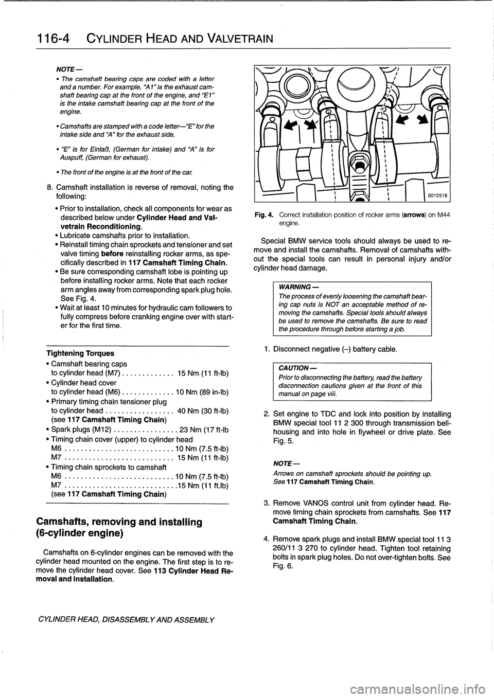
See
Fig
.
4
.
"
Wait
at
least
10
minutes
for
hydraulic
cam
followers
to
fully
compress
before
cranking
engine
over
with
start-
er
for
the
first
time
.
Tightening
Torques
"
Camshaft
bearing
caps
to
cylinder
head
(M7)
.............
15
Nm
(11
ft-Ib)
"
Cylinder
head
cover
to
cylinder
head
(M6)
.............
10
Nm
(89
in-lb)
"
Primary
timing
chain
tensioner
plug
to
cylinder
head
.
................
40
Nm
(30
ft-lb)
(sea
117
Camshaft
Timing
Chain)
"
Spark
plugs
(M12)
.............
...
23
Nm
(17
ft-lb
Timing
chaincover
(upper)
to
cylinder
head
M6
.....
.
.
...
................
.
10
Nm
(7
.5
ft-Ib)
M7
....
..
.
.
........
.
.....
.
...
.
15
Nm
(11
ft-Ib)
"
Timing
chain
sprockets
to
camshaft
M6
....
.
.
..
..............
.
..
..
10
Nm
(7
.5
ft-Ib)
M7
....
....
..............
.
..
..
.15
Nm
(11
ft
.lb)
(sea
117
Camshaft
Timing
Chain)
Camshafts,
removing
and
installing
(6-cylinder
engine)
Camshafts
on
6-cylinder
engines
can
be
removed
with
the
cylinder
head
mounted
on
the
engine
.
The
first
step
is
to
re-
move
the
cylinder
head
cover
.
See
113
Cylinder
Head
Re-
moval
and
Installation
.
CYLINDER
HEAD,
DISASSEMBLYAND
ASSEMBLY
Fig
.
4
.
Correct
installation
position
ofrocker
arms
(arrows)
on
M44
engine
.
Special
BMW
service
tools
should
always
be
used
to
re-
move
and
instan
the
camshafts
.
Removal
of
camshafts
with-
outthe
special
tools
can
result
in
personal
injury
and/or
cylinder
head
damage
.
WARNING
-
The
processof
evenly
loosening
the
camshaft
bear-
ing
cap
nuts
is
NOT
en
acceptable
method
of
re-
moving
the
camshafts
.
Special
tools
shouldalways
be
used
lo
remove
the
camshafts
.
Be
sure
to
read
the
procedure
through
before
starting
ajob
.
1
.
Disconnect
negative
(-)
battery
cable
.
CAUTION-
Prior
to
disconnectiog
the
battery,
read
the
battery
disconnection
cautions
given
at
the
front
of
this
manual
onpaga
viii
.
516
2
.
Setengine
to
TDC
and
lock
into
position
by
installing
BMW
special
tool
11
2
300
through
transmission
bell-
housing
and
into
hole
in
flywheel
or
drive
platea
See
Fig
.
5
.
NOTE-
Arrows
on
camshaft
sprockets
shouldbe
pointing
up
.
Sea
117
Camshaft
Timing
Chain
.
3
.
Remove
VANOS
control
unit
from
cylinder
head
.
Re-
move
timing
chainsprockets
from
camshafts
.
See117
Camshaft
Timing
Chain
.
4
.
Remove
sparkplugs
and
insta¡¡
BMW
special
tool
11
3
260/11
3
270
to
cylinder
head
.
Tighten
tool
retaining
bolts
in
spark
plug
holes
.
Do
not
ovar-tighten
bolts
.
See
Fig
.
6
.
Page 89 of 759
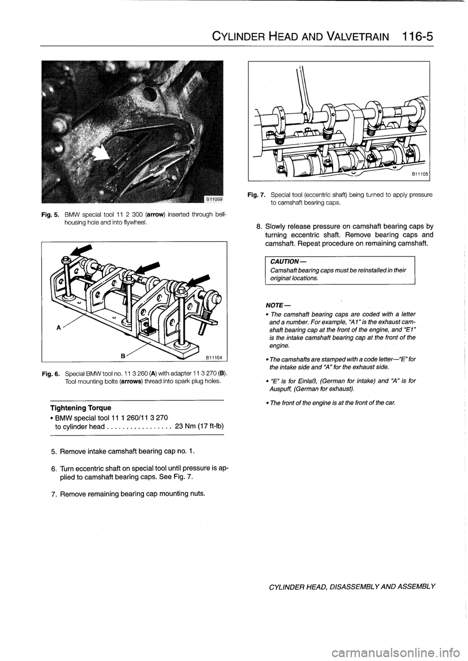
Fig
.
5
.
BMW
special
tool
11
2300
(arrow)
inserted
through
bell-
housing
hole
and
finto
flywheel
.
A
Tightening
Torque
"
BMW
special
tool11
1
260/11
3
270
to
cylinder
head
.................
23
Nm
(17
ft-Ib)
5
.
Remove
intake
camshaft
bearing
cap
no
.
1
.
6
.
Turn
eccentric
shaft
on
special
tool
until
pressure
is
ap-
plied
to
camshaft
bearing
caps
.
See
Fig
.
7
.
7
.
Remove
remaining
bearing
capmounting
nuts
.
CYLINDER
HEAD
AND
VALVETRAIN
116-
5
NOTE-
Fig
.
7
.
Special
tool
(eccentric
shaft)
beingturned
to
apply
pressure
to
camshaft
bearing
caps
.
8
.
Slowly
release
pressure
oncamshaft
bearing
capsby
turning
eccentric
shaft
.
Remove
bearing
caps
and
camshaft
.
Repeat
procedure
on
remaining
camshaft
.
CAUTION-
Camshaft
bearing
capsmust
be
reinstalled
in
their
original
locations
.
"
The
camshaft
bearing
caps
are
coded
with
a
letter
and
a
number
.
For
example,
`A1
"is
the
exhaust
cam-
shaft
bearing
cap
at
the
front
of
the
engine,
and
"E1"
is
the
intake
camshaft
bearing
cap
at
the
front
of
the
engine
.
"
The
camshaftsare
stamped
with
a
code
letter-`E"
for
the
intake
síde
and
`A"
for
the
exhaust
side
.
F19
.6
.
Special
BMW
tool
no
.
11
3260
(A)
with
adapter
ll
3
270
(B)
.
Tool
mounting
bolts
(arrows)
thread
into
spark
plug
holes
.
"
"E"
is
for
Einfal3,
(German
for
intake)
and
`A"
is
for
Auspuff,
(German
for
exhaust)
.
"
The
front
of
the
engine
is
at
the
front
of
the
car
.
CYLINDER
HEAD,
DISASSEMBLYAND
ASSEMBLY