disconnect oxygen sensor BMW 318i 1994 E36 User Guide
[x] Cancel search | Manufacturer: BMW, Model Year: 1994, Model line: 318i, Model: BMW 318i 1994 E36Pages: 759
Page 235 of 759

GENERAL
.
.
.
.
.
.
.
.
.
................
.
.
.
250-1
AUTOMATIC
TRANSMISSION
GEARSHIFT
...
.
.........
.
.
.
.
.
.
.
.
.
.
.
.
.
.
250-3
MANUAL
TRANSMISSION
Gearshift
mechanism,
adjusting
GEARSHIFT
.
.
.
.
.
.
.
.....
.
..........
.
.
.
250-1
(automatictransmission)
..
.
.
.
.
.
.
.
.
.
...
.
.
250-3
Gearshift
lever,
removing
Gear
position/neutral
safety
switch,
replacing
(manual
transmission)
.
.
.
.
...
.
.
.
.......
250-1
(automatic
transmission)
..
.
.
.
.........
.
.
250-4
Gearshift
lever,
installing
Automatic
shiftlock,
checking
function
(manual
transmission)
.
.
.
.
.
.
.
.
.
.
.......
250-2
(automatic
transmission)
..
..
...
.
.
.
....
..
250-5
Shiftinterlock,
checking
function
(automatic
transmission)
.......
.
.
.
.....
.250-6
GENERAL
This
repair
group
covers
transmission
gearshift
and
linkage
service
.
Special
service
tools
are
required
for
some
of
the
proce-
dures
given
here
.
To
gain
access
to
the
complete
gearshift
mechanism
ít
is
necessary
to
remove
the
exhaust
system
and
the
driveshaft
as
described
in
180
Exhaust
System
and260
Driveshaft
.
MANUAL
TRANSMISSION
GEARSHIFT
Gearshift
lever,
removing
(manual
transmission)
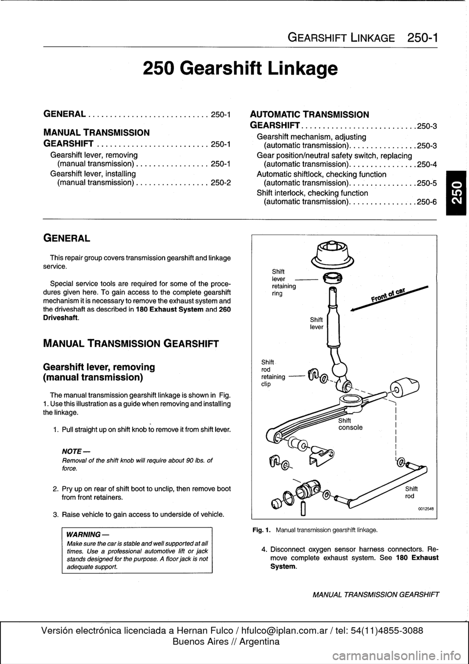
The
manual
transmission
gearshift
linkage
is
shown
in
Fig
.1
.
Use
thisillustration
asaguide
when
removing
and
installing
the
linkage
.
1
.
Pull
straight
upon
shift
knob
lo
remove
it
from
shift
lever
.
NOTE
-
Removal
of
the
shift
knob
will
require
about
90
lbs
.
of
force
.
2
.
Pry
upon
rear
of
shift
boot
tounclip,
then
remove
boot
from
front
retainers
.
3
.
Raise
vehicle
togain
access
to
underside
of
vehicle
.
WARNING
-
Make
sure
thecar
is
stable
and
well
supported
at
afl
times
.
Use
a
professional
automotive
lift
orjackstands
designed
for
the
purpose
.
A
floor
jack
is
not
adequate
support
.
250
Gearshift
Linkage
GEARSHIFT
LINKAGE
250-1
Fig
.1
.
Manual
transmission
gearshift
linkage
.
4
.
Disconnect
oxygen
sensorharness
connectors
.
Re-
move
completeexhaust
system
.
See
180
Exhaust
System
.
MANUAL
TRANSMISSION
GEARSHIFT
Page 244 of 759

260-
4
DRIVESHAFT
CAUTION
-
The
maximum
allowable
change
in
height
of
the
center
bearing
or
transmission
support
using
shims
is
3
mm
(0
.12
in
.)
.
Driveshaft,
removing
WARNING
-
"
Be
sure
the
wheels
are
off
the
ground
before
re-
moving
the
driveshaft
.
Set
the
parking
brake
be-
fore
removing
the
driveshaft
.
"
Once
the
driveshaft
has
been
removed,
the
vehi-
cle
can
roll
regardless
of
whether
the
transmis-
sion
isin
gear
or
not
.
"
The
driveshaft
fs
mounted
to
thetransmission
and
final
drive
with
self-locking
nuts
.
These
nuts
are
designed
to
be
used
only
once
and
should
be
replaced
during
reassembly
.
1.
Disconnect
oxygen
sensor
electrical
connectors
and
remove
complete
exhaustsystem
.
See
180
Exhaust
System
.
4
.
Remove
driveshaft
mounting
bolts
.
See
Fig
.
3
.
Discard
old
nuts
.
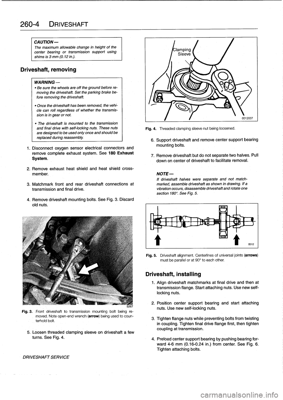
JG
Fig
.
3
.
Front
driveshaft
totransmission
mounting
bolt
being
re-
moved
.
Note
open-end
wrench
(arrow)
being
used
to
coun-
terhold
bolt
.
5
.
Loosen
threaded
clamping
sleeve
on
driveshaft
a
few
tucos
.
See
Fig
.
4
.
DRIVESHAFT
SERVICE
Fig
.
4
.
Threaded
clamping
sleeve
nut
being
loosened
.
0012037
6
.
Support
driveshaft
andremove
center
support
bearing
mounting
bolts
.
7
.
Remove
driveshaft
but
do
not
separate
two
halves
.
Pull
down
on
center
of
driveshaft
to
facilitate
removal
.
2
.
Remove
exhaust
heat
shield
and
heat
shieldcross-
member
.
NOTE-
If
driveshaft
halves
were
separate
and
not
match-
3
.
Matchmark
front
and
rear
driveshaft
connections
at
marked,
assemble
driveshaft
as
shown
in
drawing
.
If
a
transmissíon
and
final
drive
.
vibration
occurs,
disassemble
driveshaftand
rotate
one
section
180°
.
See
Fig
.
5
.
Driveshaft,
installing
Fig
.
5
.
Driveshaft
alignment
.
Centerlinesof
universal
joints
(arrows)
must
be
parallel
or
at
90°
to
each
other
1
.
Align
driveshaft
matchmarks
at
final
drive
and
then
at
transmission
flange
.
Start
attaching
nuts
.
Use
new
self-
locking
nuts
.
2
.
Position
center
support
bearing
and
start
attaching
nuts
.
Use
new
self-locking
nuts
.
3
.
Tighten
flangenuts
while
preventing
bolts
from
twisting
in
coupling
.
Tighten
final
drive
flange
first,
then
tighten
coupling
at
transmission
.
4
.
Preload
center
support
bearing
by
pushing
bearing
for-
ward4-6
mm
(0
.16-0
.24
in
.)
from
center
.
See
Fig
.
6
.
Tighten
attaching
bolts
.