disconnect oxygen sensor BMW 318i 1994 E36 Workshop Manual
[x] Cancel search | Manufacturer: BMW, Model Year: 1994, Model line: 318i, Model: BMW 318i 1994 E36Pages: 759
Page 38 of 759
020-
1
6
MAINTENANCE
PROGRAM
Fuel
filter,
replacing
Oxygen
sensor
(regulating)
\
Catalytic
Oxygen
sensor
convertor
(monitoring)
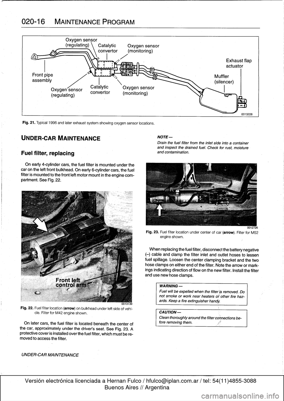
Fig
.
21
.
Typical
1996
and
later
exhaust
system
showing
oxygen
sensor
locations
.
UNDER-CAR
MAINTENANCE
convertor
On
early
4-cylínder
cars,
the
fuel
filter
is
mounted
under
the
caron
the
left
front
bulkhead
.
On
early
6-cylínder
cars,
the
fuel
filter
is
mounted
to
the
front
left
motor
mount
in
theengine
com-
partment
.
See
Fig
.
22
.
0013139
Fig
.
22
.
Fuel
filter
location
(arrow)
on
bulkheadunder
left
side
of
vehi-
cle
.
Filter
for
M42
engine
shown
.
On
later
cars,
the
fuel
filter
is
located
beneath
the
centerof
the
car,
approximately
under
the
driver's
seat
.
See
Fig
.
23
.
A
protective
cover
is
installed
overthe
fuel
filter,
which
must
be
re-
moved
to
access
the
filter
.
UNDER-CAR
MAINTENANCE
Exhaust
flap
actuator
(monitoring)
NOTE-
Drain
the
fuel
filter
trom
the
inlet
side
into
a
container
and
inspect
the
drained
fuel
.
Check
for
rust,
moisture
and
contamination
.
WARNING
-
Fuel
will
be
expelled
when
the
filter
is
removed
.
Do
not
smoke
or
worknear
heaters
or'other
fire
haz-ards
.
Keep
a
tire
extinguisher
handy
.
CAUTION-
Clean
thoroughly
around
the
filter
connections
be-
fore
removing
them
.
0012726
Fig
.
23
.
Fuel
filter
location
under
center
of
car
(arrow)
.
Filter
for
M52
engine
shown
.
Catálytic
\
Oxygen
sensor
When
replacing
the
fuel
filter,
disconnect
the
battery
negative
(-)
cable
and
clamp
the
filter
inlet
and
outlet
hoses
to
lessen
fuel
spillage
.
Loosen
thecenter
clamping
bracket
and
the
two
hoseclampson
either
end
of
the
filter
.
Note
the
arrow
or
mark-
ings
indicating
direction
of
flow
on
the
new
filter
.
Install
the
filter
anduse
new
hose
clamps
.
Page 51 of 759
NOTE-
"
On
carswith
OBD
ti,
specialized
OBD
11
scan
tool
equipment
must
be
used
to
access
the
DTCs,
either
using
the
BMW
special
tool
ora
`generic"
OBD
11
scan
tool
.
See
130
Fuel
Injection
.
"
The
08D
11
fault
memory
(including
an
iiluminated
Check
Engine
light)
can
only
be
reset
using
the
spe-
cial
scan
tool
.
Removing
the
connector
from
the
ECM
or
disconnecting
the
battery
will
not
erase
the
fault
memory
.
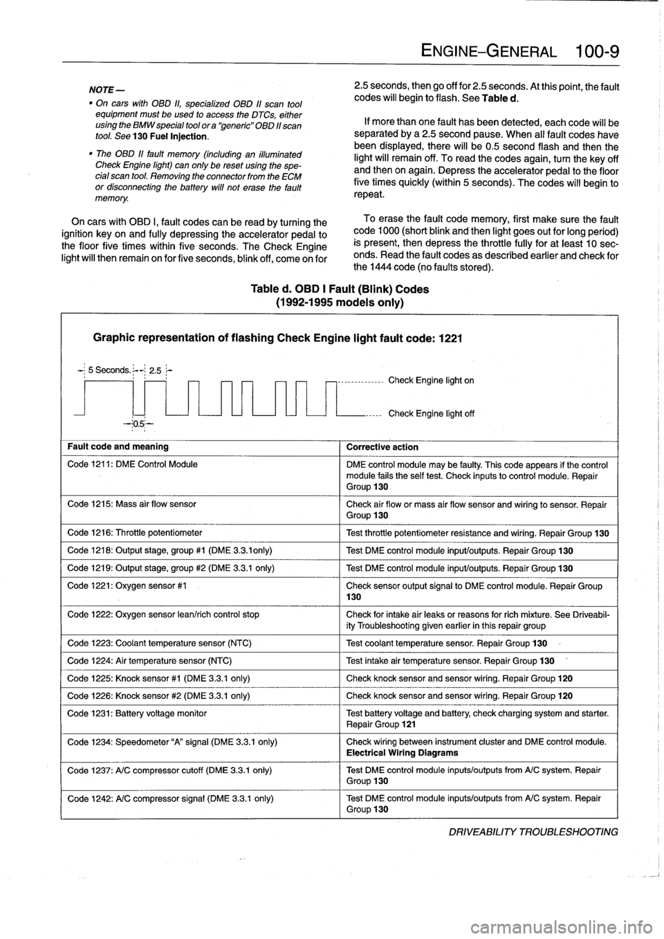
Table
d
.
OBD
1
Fault
(Blink)
Codes
(1992-1995
modeis
only)
Graphic
representation
of
flashing
Check
Engine
light
fault
code
:
1221
5
Seconds
.
:-
2
.5~-
--05--
Fault
code
and
meaning
1
Corrective
action
Code
1216
:
Throttle
potentiometer
Code
1218
:
Output
stage,
group#1
(DME
3
.3
.ionly)
Code
1219
:
Output
stage,
group
#2
(DME
3
.3.1
only)
Code
1221
:
Oxygen
sensor
#1
Code
1224
:
Air
temperature
sensor
(NTC)
Code
1226
:
Knock
sensor
#2
(DME
3
.3
.1
only)
130
ENGINE-GENERAL
100-
9
2
.5
seconds,
then
go
off
for
2
.5
seconds
.
At
thispoint,
the
fault
codes
will
begin
to
flash
.
See
Table
d
.
If
more
than
one
fault
has
been
detected,
eachcode
will
be
separated
by
a2
.5
second
pause
.
When
al¡
fault
codes
havebeen
displayed,
there
will
be0
.5
second
flash
and
thenthe
light
will
remain
off
.
To
read
the
codes
again,
turn
the
key
off
and
then
on
again
.
Depress
theaccelerator
pedal
to
the
floor
five
times
quickly
(within
5
seconds)
.
The
codes
will
begin
to
repeat
.
On
cars
with
OBD
I,
fault
codes
can
be
read
by
turning
the
To
erase
the
fault
code
memory,
first
make
sure
the
fault
ignition
key
on
and
fully
depressing
theaccelerator
pedal
to
code
1000
(short
blink
and
then
light
goes
out
for
long
period)
the
floor
five
times
within
five
seconds
.
TheCheck
Engine
is
present,
then
depress
the
throttle
fully
for
at
least
10
sec-
light
will
then
remain
on
for
five
seconds,
blink
off,
come
on
for
onds
.
Read
the
fault
codes
as
described
earlier
and
check
for
the
1444
code
(no
faults
stored)
.
-,--------------
Check
Engine
light
on
Check
Engine
light
off
Code
1211
:
DM
E
Control
Module
DME
control
module
may
be
faulty
.
This
code
appears
if
the
control
module
fails
the
self
test
.
Check
inputsto
control
module
.
Repair
Group
130
Code
1215
:
Mass
air
flow
sensor
Check
air
flow
or
mass
air
flow
sensor
and
wiring
to
sensor
.
Repair
Group
130
Test
throttle
potentiometer
resistance
and
wiring
.
Repair
Group
130
Test
DME
control
module
input/outputs
.
Repair
Group
130
Test
DME
control
module
input/outputs
.
Repair
Group
130
Check
sensor
output
signal
to
DME
control
module
.
Repair
Group
Code
1222
:
Oxygen
sensor
lean/rich
control
stop
Check
for
intake
air
leaks
or
reasons
forrich
míxture
.
See
Driveabil-
ity
Troubleshooting
given
earlier
in
this
repair
group
Code
1223
:
Coolant
temperaturesensor
(NTC)
1
Test
coolant
temperature
sensor
.
Repair
Group
130
Test
intake
air
temperature
sensor
.
Repair
Group
130
Code
1225
:
Knock
sensor#1
(DME
3
.3
.1
only)
1
Check
knocksensorand
sensor
wiring
.
Repair
Group
120
Check
knocksensor
and
sensor
wiring
.
Repair
Group
120
Code
1231
:
Batteryvoltage
monitor
Test
battery
voltage
and
battery
check
charging
system
and
starter
.
Repair
Group
121
Code
1234
:
Speedometer
"A"signal
(DME
3
.3
.1
only)
Check
wiring
between
instrument
cluster
and
DME
control
module
.
Electrical
Wiring
Diagrams
Code
1237
:
A/C
compressor
cutoff
(DME
3
.3
.1
only)
Test
DME
control
module
inputs/outputs
from
A/C
system
.
Repair
Group
130
Code
1242
:
A/C
compressor
signal
(DME
3
.3.1
only)
Test
DME
control
module
inputs/outputs
from
A/C
system
.
Repair
Group
130
DRIVEABILITY
TROLIBLESHOOTING
Page 53 of 759
Graphic
representation
of
flashing
Check
Engine
light
fault
code
:
1221
-
;
5
Seconds
.
~-
2
.5;-
Fault
code
and
meaning
Corrective
action
Code
1286
:
Knock
control
test
pulse
(DME
3
.3
.1
only)
Check
DME
control
module
inputs/outputs
.
Control
module
may
be
faulty
Repair
Group
130
Code
1000
(light
remains
off)
:
End
of
fault
code
output-all
fault
codes
have
been
displayed
.
No
~
corrective
action
necessary
.
Repeat
test
if
necessary
Code
1444
:
No
more
faults
.
No
corrective
action
necessary
.
This
code
must
be
present
lo
erase
fault
memory
Basic
Requirements
Preventive
Maintenance
The
following
list
contains
basic
checks
that
should
be
made
when
experiencing
driveability
problems
.
1
.
Check
intake
(induction)
system
for
leaks
.
Check
for
cracked,
loose,
or
disconnected
hoses
and
duct
work
.
Check
that
all
hose
clamps
are
tight
.
NOTE-
An
air
leak
allows
unmeasured
airto
enter
the
engine,
offen
resulting
in
an
in
overly
lean
fuel
mixture
and
causing
driveability
problems
which
will
cause
the
Check
Engine
light
to
come
on
.
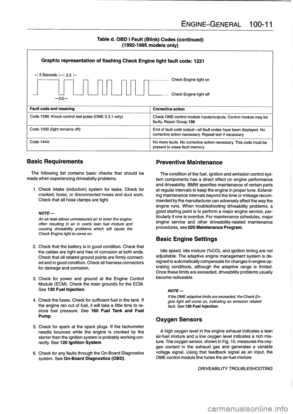
Table
d
.
OBD
I
Fault
(Blink)
Codes
(continued)
(1992-1995
models
only)
7
-
1
--------------
Check
Engine
light
on
ENGINE-GENERAL
100-
1
1
Check
Engine
light
off
The
condition
of
the
fuel,
ignition
and
emission
controlsys-
tem
components
has
a
directeffect
onengineperformance
and
driveability
.
BMW
specifies
maintenance
of
certain
parts
at
regular
intervals
lo
keep
the
engine
in
proper
tune
.
Extend-
ing
maintenance
intervals
beyond
the
time
or
mileagerecom-
mended
bythe
manufacturer
can
adversely
affect
the
way
the
engine
runs
.
When
troubleshooting
driveability
problems,
a
good
starting
point
is
to
perform
a
major
engine
service,par-
ticularly
if
one
is
overdue
.
For
maintenance
schedules,
major
engine
service
and
other
driveability-related
maintenance
procedures,
see020
Maintenance
Program
.
Basic
Engine
Settings
2
.
Check
that
the
battery
isin
good
condition
.
Check
that
the
cables
are
tight
and
free
of
corrosion
at
both
ends
.
Idle
speed,
idle
mixture
(%CO),
and
ignition
timing
are
not
Check
that
all
related
ground
points
are
firmly
connect-
adjustable
.
The
adaptive
engine
management
system
is
de-
ed
and
in
good
condition
.
Check
al¡
harness
connectors
signed
lo
automatically
compensate
for
changes
in
engine
op-
for
damage
and
corrosion
.
erating
conditions,
although
the
adaptive
range
is
limited
.
Once
these
limits
are
exceeded,
driveability
problems
usually
3
.
Check
for
prwer
and
ground
at
the
Engine
Control
become
noticeable
.
Module
(ECM)
.
Check
the
main
grounds
for
the
ECM
.
See130
Fuel
Injection
.
NOTE-
If
the
DME
adaptive
limits
are
exceeded,
the
Check
En-
4
.
Check
the
fuses
.
Check
for
sufficient
fuel
in
the
tank
.
If
gine
light
will
come
on,
indicating
an
emission
related
the
engine
ranout
of
fuel,
it
will
take
a
little
time
to
re-
fault
.
See
130
Fuel
Injection,
store
fuel
pressure
.
See
160
Fuel
Tank
and
Fuel
Pump
.
Oxygen
Sensors
5
.
Check
for
spark
at
the
spark
plugs
.
If
the
tachometer
needle
bounces
while
the
engine
is
crankedby
the
A
high
oxygen
level
in
the
engine
exhaust
indicates
a
lean
starter
then
the
ignition
system
is
probably
working
cor-
air-fuel
mixture
and
a
low
oxygen
level
indicates
a
rich
mix
rectly
.
See
120
Ignition
System
.
ture
.
The
oxygen
sensor,
shown
in
Fig
.
10,
measures
the
oxy-
gen
content
in
the
exhaust
gasand
generates
a
variable
6
.
Check
for
any
faults
through
the
On-Board
Diagnostics
voltage
signal
.
Using
that
feedback
signal
asan
input,
the
system
.
See
On-Board
Diagnostics
(OBD)
.
DME
control
module
fine
tunes
the
air-fuel
mixture
.
DRIVEABILITY
TROUBLESHOOTING
Page 149 of 759
FUEL
INJECTION
130-
3
Fuel
metering
.
The
ECM
meters
fuel
bychanging
the
The
engine
management
system
compensates
automatical-
opening
time
(pulsewidth)
of
the
fuel
injectors
.
To
ensure
that
ly
for
changes
in
the
engine
due
to
age,
minor
wear
or
small
injector
pulsewídth
is
the
only
factor
that
determines
fuel
me-
problems,
such
as
a
disconnected
vacuum
hose
.
Asa
result,
tering,fuel
pressure
is
maintained
bya
fuel
pressure
regula-
idle
speed
and
mixture
do
not
need
lo
be
adjustedas
partof
tor
.
The
injectors
are
mounted
lo
a
common
fuel
supply
called
routine
maintenance
.
the
fuel
rail
.
The
ECM
monitors
engine
speed
to
determine
the
duration
NOTE-
ofinjector
openings
.
Other
signals
to
the
ECM
help
determine
Poordriveabilitymaybe
encountered
when
the
batteryis
injector
pulse
time
for
different
operating
conditions
.
A
tem-
disconnected
and
reconnected
.
when
the
battery
is
dis-
connected,
the
adaptive
memory
is
lost
The
system
will
perature
sensor
signals
engine
temperature
for
mixture
adap-
readaptafterabout
ten
minutes
of
drfving
.
tion
.
A
throttle
position
sensor
signals
throttle
position
.
The
exhaust
oxygen
sensor(s)
signal
information
about
combus-
tion
efficiency
for
control
of
the
air-fuel
mixture
.
1992
to
1995
DISA
(Dual
Resonance
Intake
System)
engines
are
equipped
with
a
single
sensor
.
1996
and
later
(OBD
II)
engines
are
equipped
with
an
oxygen
sensor
before
TheE36
4-cylinder
engine
is
equipped
with
a
dual
intake
andone
after
each
catalytic
converter
.
Forexample,the
M52
runner
system,
termed
DISA
.
DISA
offers
the
advantages
of
engine
is
equipped
withfour
oxygen
sensors
.
both
short
and
long
intake
pipes
.
Long
intake
runners
are
most
useful
at
low
to
medium
engine
rpm
for
producing
good
Idle
speed
control
.
ldle
speed
is
electronically
controlled
torque
characteristics
.
Short
intake
runners
produce
hígherviathe
idle
speed
control
valve,
which
maintains
idle
speed
by
horsepower
at
hígher
engine
speeds
.
bypassing
varying
amounts
of
air
around
theclosed
throttle
valve
.
Idle
speed
is
not
adjustable
.
NOTE-
Knock
(detonation)
control
.
Knock
sensors
monitor
and
The
term
DISA
comes
from
the
German
words
Differen-
control
ignition
knock
through
the
ECM
.
The
knock
sensors
zierte
Sauganlage,
and
can
roughlybe
translated
as
"dif-
fering
intake
manifold
configuration
."
See
100
Engine-
function
like
microphones
and
are
able
to
convert
mechanical
General
foradditional
information
on
DISA
operation
.
vibration
(knock)
into
electrical
signals
.
The
ECM
is
pro-
grammed
to
react
to
frequencies
that
are
characteristic
of
en-
Manifold
construction
:
The
intake
manifold
is
a
two-piece
gine
knock
and
adapt
the
ignition
timing
point
accordingly
.
metal
construction,
with
a
pair
of
runners
in
thetop
section
See120
Ignition
System
for
further
details
.
and
four
runners
in
the
lower
section
.
A
butterfly
valve
is
in-
stalled
in
the
lower
section,
enabling
the
DISA
solenoid
toiso-
NOTE-
late
one
pair
of
runners
from
the
other
pair
.
See
Fig
.
2
.
The
1992
M50
engine
is
not
equipped
with
knock
sen-
Operation
.
With
the
DISA
butterfly
valve
closed,
the
pipes
sors
.
All
other
engines
are
equipped
with
two
knock
in
thetop
half
of
the
manifold
act
together
with
the
ram
air
sensors
.
pipes
in
the
lower
halfto
producea
single,
long
air
intake
pipe
for
each
cylinder
.
See
Fig
.
3
.
The
column
of
aír
oscíllating
in
Basic
Engine
Settings
this
combined
pipe
significantly
increases
engine
torque
in
the
medium
rpm
range
.
Idle
speed,
idle
mixture
(%CO),
and
ignition
timing
arenot
adjustable
.
The
adaptive
engine
management
system
is
de-
signed
to
automatically
compensate
for
changes
in
engine
op-
eratingconditions,
although
the
adaptive
range
is
limited
.
Once
these
limits
are
exceeded,
driveability
problems
usually
be-
come
noticeable
.
Above
approximately
4,800
rpm,
the
butterfly
valve
between
the
intake
air
pipes
for
the
two
cylinder
groups
is
opened
.
The
shorter
pipes
in
the
lower
manifold
section
now
become
the
main
suppliers
of
ram
air
to
the
cylinders,yielding
greater
pow-
er
at
the
upper
end
of
the
engine
rpm
range
.
See
Fig
.
4
.
Control
components
.
The
DISA
butterfly
valve
is
actuated
NOTE-
electro-pneumatically
via
the
engine
control
module
(ECM)
.
lf
the
system
adaptive
limits
are
exceeded,
the
Check
The
valve
begins
to
open
as
engine
speed
rises
aboye
4,840
Engine
light
will
most
likely
come
on,
indicating
an
rpmand
closes
below
4,760
rpm
.
The
action
of
the
valve
is
de-
emissions-
related
fault
For
Check
Engine
light
diag-
liberately
delayed
to
prevent
it
from
opening
and
closing
repeat-
nostics,
see100
Engine-General
.
edly
within
a
short
time
.
GENERAL
Page 152 of 759
130-
6
FUEL
INJECTION
Warnings
and
Cautions
For
personal
safety,
as
well
as
the
protection
of
sensitive
electronic
components,
the
following
warnings
and
cautions
should
be
adhered
to
when
working
on
the
engine
manage-
ment
system
.
GENERAL
WARNING
-
"
The
ignition
system
produces
high
voltages
that
can
be
fatal
.
Avoid
contact
with
exposed
termi-
nals
.
Use
extreme
caution
when
working
onacar
with
the
ignition
switched
on
or
the
engine
run-
ning
.
"
Do
not
touch
or
disconnect
any
high
voltage
ca-
bles
from
the
coils
or
spark
plugs
while
the
engine
is
running
or
beingcranked
by
the
starter
.
"
Connect
and
disconnect
the
DME
system
wiring
and
test
equipment
leads
only
when
the
ignition
is
switched
off
.
"
Gasoline
is
highly
flammable
and
fts
vaporsare
explosive
.
Do
not
smoke
or
work
on
a
car
near
heaters
or
other
fire
hazards
when
diagnosing
and
repalring
fuel
system
problems
.
Have
a
tire
extinguisher
avaílable
in
case
of
an
emergency
.
"
When
working
onan
open
fuel
system,
wear
suit-
able
hand
protection,
asprolonged
contact
wfth
fuel
can
cause
illnesses
and
skin
disorders
.
"
Renew
fuel
system
hoses,
clamps
and
O-rings
any
timethey
are
removed
.
"
Before
makingany
electrical
tests
that
require
the
engine
to
be
cranked
using
the
starter,
disable
the
ignition
system
as
described
in
120
Ignition
System
.
CAUTION-
"
Prior
to
disconnecting
the
battery,
read
the
bat-
tery
disconnectinn
cautions
given
at
the
front
of
this
manual
onpage
vifi
.
"
Do
not
connect
any
test
equipment
that
delivers
a
12-volt
power
supply
to
terminal
15
(+)
of
the
ig-
nitioncoil
.
The
current
flow
may
damage
the
ECM
.
In
general,
connect
test
equipment
only
as
speclfied
by
BMW,
this
manual,
or
the
equipment
maker
.
"
Only
use
a
digital
multlmeter
for
electrical
test
.
"
Only
use
an
LED
test
light
for
quick
tests
.
"
Disconnecting
the
battery
may
erase
fault
code(s)
stored
in
memory
.
Check
for
fault
codes
prior
to
disconnecting
the
battery
cables
.
ff
the
Check
Engine
light
ís
illuminated,
see100En-
gine-General
for
DME
fault
code
information
.
ff
any
other
system
faults
have
been
detected
(indi-
catedbyan
illuminated
warning
light),
see
an
au-
thorized
BMW
dealer
.
Additional
systems
with
self-diagnostic
capabilities
include,
ABS
(Anti-
lock
brakes),
SRS
(Airbags),
EML
and
ASC+T
and
AST
(Traction
Control)
.
"
Do
not
run
the
engine
wfth
any
of
the
spark
plug
wires
dlsconnected
.
Catalytic
converter
damage
may
result
.
"
Always
waitat
least
40
seconds
afterturning
off
the
ignition
before
removing
the
engine
control
module
(ECM)
connector
.
ff
the
connector
isre-
moved
before
this
time,
residual
power
in
the
sys-
tem
relay
may
damage
the
control
module
.
"
Cleanliness
is
essential
when
working
onan
open
fuel
system
.
Thoroughly
clean
fuel
line
con-
nections
and
surroundlng
areas
before
loosen-
ing
.
Avoid
moving
the
car
.
Only
fnstall
cleanparts
.
"
Fuel
system
cleaners
and
other
chemical
addi-
tives
other
than
those
specifically
recommended
by
BMW
may
damage
the
catalytic
converter,
the
oxygensensor
or
other
fuel
supply
components
.
Page 155 of 759
Oxygen
Sensor
FUEL
DELIVERY
TESTS
FUEL
INJECTION
130-
9
"
Voltage
at
¡dle
..
.
..
..
....
0
.2
to
0
.8
VDC,
fluctuating
Checking
fuel
delivery
is
afundamental
part
of
trouble-
shooting
and
diagnosing
the
engine
management
system
.
Fuel
pressure
directly
influences
fuel
delivery
.
An
accurate
NOTE-
fuel
pressure
gauge
will
be
needed
to
make
the
tests
.
To
check
sensorresponse
to
lean
and
rich
mixtures,
createenairleak,
orpull
vacuumhoseofffue¡
pressure
There
are
three
significant
fuel
delivery
values
to
be
mea-
regulator
to
increase
fuel
pressure
.
sured
:
3
.
Separate
sensorharness
connector
from
sensor
.
Check
for
battery
voltage
between
terminals
3
and
4
(green
wire
and
brown
wire)
in
main
wiring
harness
side
of
con-
nector
with
engine
running
.
If
voltage
is
not
present,
check
oxygen
sensor
heater
relay
.
See610
Electrical
Component
Locations
.
4
.
Check
heater
element
resistance
between
terminals
3
and
4
in
sensor
side
of
connector
.
If
element
is
electri-
cally
open
(no
continuity),
replace
sensor
.
NOTE-
The
oxygen
sensor
heater
relay
is
mounted
in
the
main
power
distributfon
box
in
the
left
rear
of
the
engine
com-
partment
.
Refer
to
Fig
.
6
.
The
heater
relay
is
energized
wíth
positive
(+)
battery
voltage
from
the
main
relayanda
switched
ground
from
the
ECM
.
See
Electrical
Wir-
ing
Diagrams
.
"
Oxygen
sensor
to
exhaust
pipe
...
..
55
Nm
(41
ft-Ib)
"
System
pressure-created
by
the
fuel
pump
and
main-
tained
by
the
pressure
regulator
.
"
Fuel
delivery
volume-created
by
the
fuel
pump
and
af-
fected
by
restrictions,
suchasclogged
fuel
filter
.
"
Residual
pressure-the
pressure
maintained
in
the
closed
system
after
the
engine
and
fuel
pump
are
shut
off
.
Procedures
for
measuring
the
first
two
quantities
arede-
scribed
in
160
Fuel
Tank
and
Fuel
Pump
.
Residual
fuel
pres-
sure
is
checked
using
the
procedure
detailed
later
in
this
group
.
Operating
fuel
pump
fortests
To
operate
the
fuel
pump
for
testing
purposes
without
hav-
íng
to
runthe
engine,
the
fuel
pump
relay
can
be
bypassed
to
power
the
pump
directly
.
Fuel
pump
relay
location
is
shown
in
Fig
.
6
.
5
.
¡f
oxygen
sensor
doesn't
produce
a
fluctuating
voltage
To
runthe
fuel
pump,
remove
the
fuel
pump
relay
and
con-
and
preheater
circuit
is
OK,
replace
sensor
.
nect
the
socket
for
relayterminal
30
to
the
socket
for
relay
ter-
mina¡
87
with
a
fused
jumper
wire
.
After
completing
the
tests,
NOTE-
remove
the
jumper
wire
.
If
not
already
applied,
coat
the
oxygen
sensor
threads
with
an
anti-seize
compound
before
installation
.
Do
not
CAUTION-
getthe
compound
on
the
sensor
tip
.
"
Relay
locations
may
vary
.
Use
care
when
identi-
fying
relays
and
making
electrical
checks
at
the
fuselrelay
panel
.
See
610
Electrical
Compo
Tightening
Torque
nent
Locations
for
additional
relay
information
.
"
The
fuel
pump
relay
has
a
1
.5
mm2
red
wire
at
ter-
minal
30
in
the
relay
socket
.
Terminal
87
has
a
1
.5
mm
2
greenlviolet
wire
.
See
Electrical
Wiring
Di-
agrams
for
additional
wiring
information
.
NOTE-
Thejumper
wire
should
be
1.5
mm2
(14
ga
.)
and
in-
clude
an
in-line
tuse
holder
with
a15
amp
tuse
.
To
avoid
fuselrelay
panel
damage
from
repeated
connect-
ing
and
disconnecting,
also
include
a
toggle
switch
.
A
heavy-duty
jumper,
BMW
tool
no
.
61
3
050,
is
also
available
from
an
authorized
BMW
dealer
.
FUEL
DELIVERYTESTS
Page 209 of 759
1
.
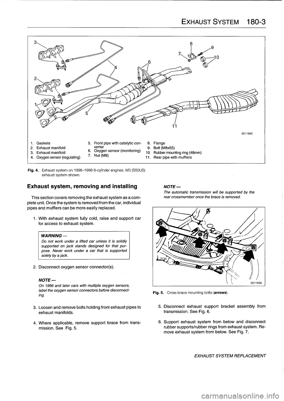
Gaskets
5
.
Front
pipe
with
catalytic
con-
8
.
Flange
2
.
Exhaust
manifold
verter
9
.
Bolt
(M8x55)
3
.
Exhaust
manifold
6
.
Oxygen
sensor
(monitoring)
10
.
Rubber
mounting
ring
(48mm)
4
.
Oxygen
sensor
(regulating)
7
.
Nut
(M8)
11
.
Rear
pipewith
mufflers
Fig
.
4
.
Exhaust
systemon
1996-1998
6-cylinder
engines
.
M3
(S50US)
exhaust
system
shown
.
Exhaust
system,
removing
and
installing
NOTE-
The
automatic
transmission
will
be
supported
by
the
This
section
covers
removing
the
exhaust
system
as
a
com-
rear
crossmember
once
the
brace
is
removed
.
plete
unit
.
Once
the
system
is
removed
from
the
car,
individual
pipes
and
mufflers
can
be
more
easily
replaced
.
1.
With
exhaust
system
fully
cold,raise
and
support
car
for
access
to
exhaustsystem
.
WARNING
-
Do
not
work
undera
lifted
car
unless
it
is
solidly
supported
on
jack
stands
designed
for
that
pur-
pose
.
Never
work
under
a
car
that
is
supported
solely
by
a
jack
.
2
.
Disconnect
oxygen
sensor
connector(s)
.
NOTE
-
On
1996
and
later
cars
with
multiple
oxygen
sensors,
label
the
oxygen
sensor
connectorsbefore
disconnect-
ing
.
4
.
Where
applicable,
remove
support
brace
from
trans-
mission
.
See
Fig
.
5
.
EXHAUSTSYSTEM
180-
3
3
.
Loosen
andremove
bolts
holding
front
exhaust
pipes
to
exhaust
manifolds
.
transmission
.
See
Fig
.
6
.
0011940
Fig
.
5
.
Crossbracemounting
bolts
(arrows)
.
5
.
Disconnect
exhaust
support
bracket
assembly
from
6
.
Supportexhaustsystem
from
below
and
dísconnect
rubbersupports/rubber
rings
from
exhaust
system
.
Re-
move
exhaust
system
from
below
.
See
Fig
.
7
.
EXHAUST
SYSTEM
REPLACEMENT
Page 211 of 759
Dimension
A=15mm
(0
.60
in
.)
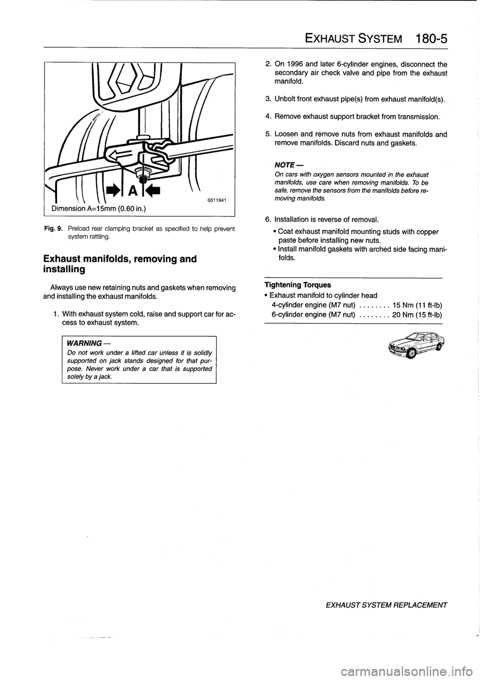
Fig
.
9
.
Preload
rear
clamping
bracket
as
specifíed
tohelp
prevent
system
rattling
.
Exhaust
manifolds,
removing
and
installing
WARNING
-
Do
not
work
under
a
lifted
car
unfess
itis
solidly
supportedonjackstands
designed
for
that
pur-
pose
.
Never
work
underacar
that
is
supported
solely
by
ajack
.
EXHAUST
SYSTEM
180-
5
2
.
On
1996
and
later
6-cylinder
engines,
disconnect
the
secondary
air
check
valve
and
eipe
from
the
exhaust
manifold
.
3
.
Unbolt
front
exhaust
pipe(s)
from
exhaust
manifold(s)
.
4
.
Remove
exhaustsupport
bracket
from
transmission
.
5
.
Loosen
andremove
nuts
fromexhaust
manifolds
and
remove
manifolds
.
Discard
nuts
and
gaskets
.
NOTE-
On
cars
wíth
oxygen
sensors
mounted
in
the
exhaust
manifolds,
usecare
when
removing
manifolds
.
Tobe
safe,
remove
the
sensors
from
the
manifolds
before
re-
moving
manifolds
.
6
.
Installation
is
reverse
of
removal
.
"
Coatexhaust
manifold
mounting
studs
with
copper
paste
before
installing
new
nuts
.
"
Insta¡¡
manifold
gaskets
with
arched
side
facing
mani-
folds
.
Always
use
new
retaining
nuts
and
gaskets
when
removing
Tightening
Torques
and
installing
the
exhaust
manifolds
.
"
Exhaust
manifold
to
cylinder
head
4-cylinder
engine
(M7
nut)
........
15
Nm
(11
ft-Ib)
1
.
With
exhaust
system
cold,raise
and
support
car
for
ac-
6-cylinder
engine
(M7
nut)
........
20
Nm
(15
ft-Ib)
cess
lo
exhaust
system
.
EXHAUST
SYSTEM
REPLACEMENT
Page 226 of 759
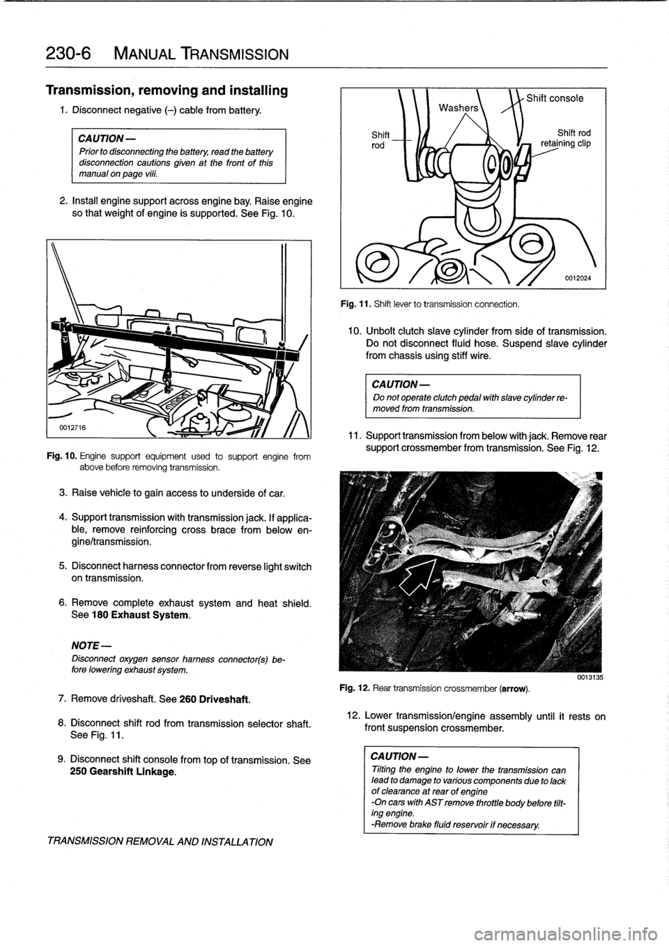
230-
6
MANUAL
TRANSMISSION
Transmission,
removing
and
installing
1
.
Disconnect
negative
(-)
cable
from
battery
.
CAUTION-
Prior
to
disconnecting
the
battery,
read
the
battery
disconnection
cautions
given
at
the
front
of
this
manual
onpage
viii
.
2
.
Insta¡¡
enginesupportacrossengine
bay
.
Raise
engine
so
that
weight
of
engine
ís
supported
.
See
Fig
.
10
.
Fig
.
10
.
Engine
support
equipment
used
to
support
engine
from
above
before
removing
transmission
.
3
.
Raise
vehicle
to
gain
access
to
underside
of
car
.
4
.
Support
transmission
with
transmission
jack
.
lf
applica-
ble,
remove
reinforcing
cross
brace
from
belowen-
gine/transmission
.
5
.
Disconnect
harnesscon
nector
from
reverse
light
switch
on
transmission
.
6
.
Remove
completeexhaustsystem
and
heat
shield
.
See
180
Exhaust
System
.
NOTE-
Disconnect
oxygensensor
hamess
connector(s)be-
fore
lowering
exhaust
system
.
7
.
Remove
driveshaft
.
See260
Driveshaft
.
8
.
Disconnect
shift
rod
from
transmission
selectorshaft
.
See
Fig
.
11
.
9
.
Disconnect
shift
console
fromtop
of
transmission
.
See
250
Gearshift
Linkage
.
TRANSMISSION
REMOVAL
AND
INSTALLATION
Washers
Shift
Shift
rod
rod
retaining
clip
0
0
,
Fig
.
11
.
Shift
lever
to
transmission
connection
.
Shift
console
0012024
10
.
Unbolt
clutch
slave
cylinder
from
sideof
transmission
.
Do
not
disconnect
fluid
hose
.
Suspend
slavecylinder
from
chassis
using
stiff
wire
.
CAUTION-
Do
not
operate
clutch
pedal
with
slave
cylinder
re-
moved
from
transmission
.
11
.
Support
transmission
from
below
with
jack
.
Remove
rear
support
crossmember
from
transmission
.
See
Fig
.
12
.
Fig
.
12
.
Rear
transmission
crossmember
(arrow)
.
12
.
Lower
transmission/engine
assembly
until
it
rests
on
front
suspension
crossmember
.
CAUTION-
Tilting
the
engine
to
lower
thetransmission
can
lead
to
damage
to
various
componente
due
to
lackof
clearance
at
rear
of
engine
-On
cars
with
AST
remove
throttle
body
before
tilt-
ing
engine
.
-Remove
brace
fluid
reservoir
if
necessary
.
0013135
Page 232 of 759
240-
4
AUTOMATIC
TRANSMISSION
TRANSMISSION
REMOVALAND
INSTALLATION
Removal
and
installation
of
thetransmission
is
best
accom-
plished
on
a
lift
using
a
transmission
jack
.
Use
caution
and
safe
workshop
practices
when
working
beneath
car
and
low-
ering
transmission
.
WARNING
-
To
lift
the
vehicle
safely,
see010
Fundamentals
for
the
Do-it-Yourself
Owner
.
CAUTION-
"
Be
sure
the
vehicle
is
properly
supported
.
The
removal
of
the
transmission
may
upset
the
bal-
ance
of
the
vehicle
on
a
lift
.
"
Tilting
the
engine
to
remove
the
transmission
can
lead
to
damage
to
various
components
due
to
lack
of
clearance
.
-On
carswith
AST
remove
throttle
body
.
-Remove
brake
fluid
reservoir
if
necessary
.
Torx-head
bolts
are
used
to
mount
thetransmission
to
the
bellhousing
.
Be
sure
to
have
appropriate
tools
on
hand
before
starting
thejob
.
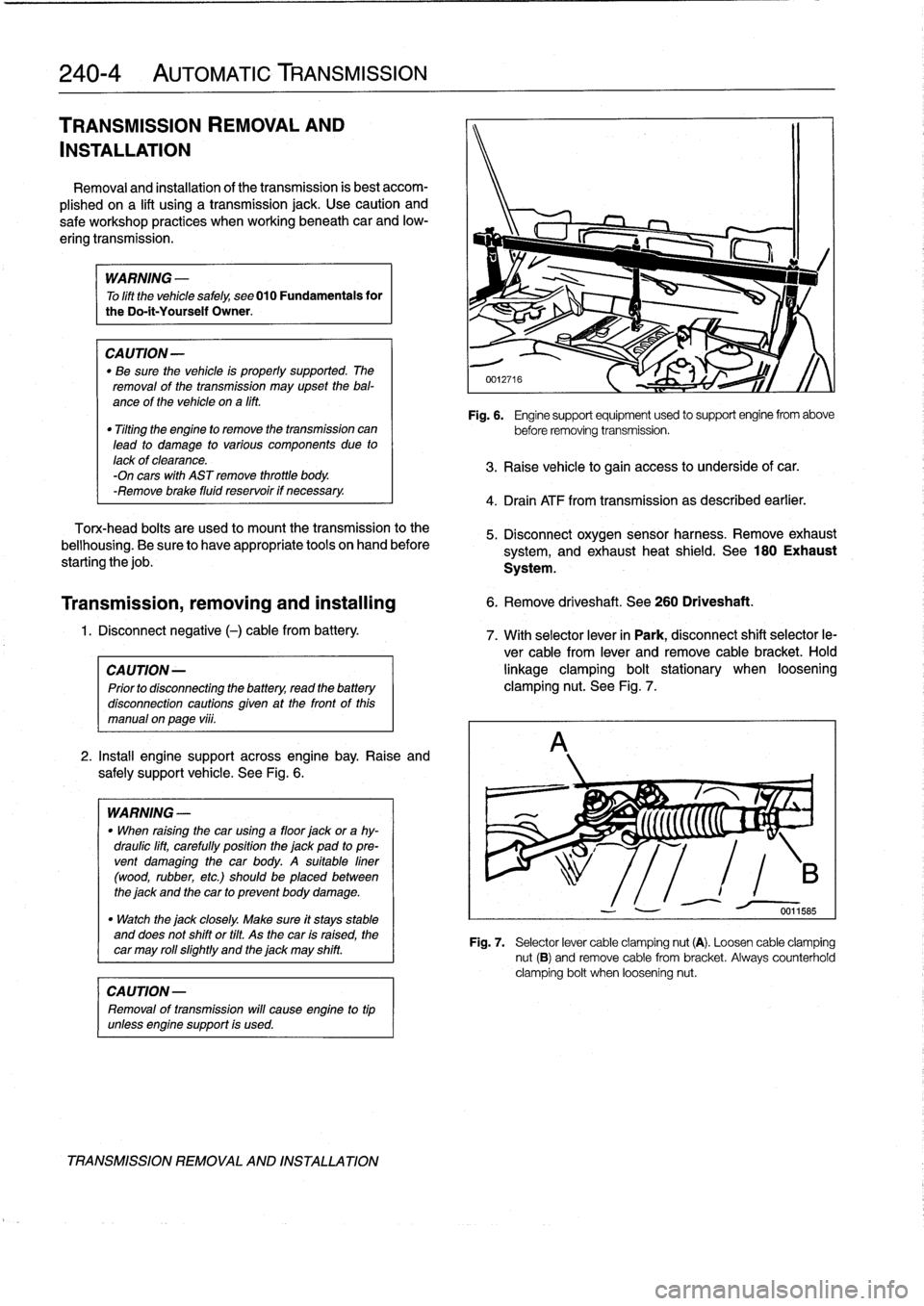
2
.
Install
engine
support
across
engine
bay
.
Raise
and
safely
support
vehicle
.
See
Fig
.
6
.
WARNING
-
"
When
raising
thecar
using
a
floor
jack
or
a
hy-
draulic
lift,
carefully
position
the
jack
pad
to
pre-
vent
damaging
the
car
body
.
A
suitable
liner
(wood,
rubber,
etc
.)
should
be
placed
between
the
jack
and
the
car
to
prevent
body
damage
.
"
Watch
the
jack
closely
.
Make
sure
it
stays
stable
and
does
not
shift
or
tilt
.
As
the
car
is
raised,
the
car
may
roll
slightty
and
the
jack
may
shift
.
CAUTION-
Removal
of
transmission
will
cause
engine
to
tip
unlessengine
support
is
used
.
TRANSMISSION
REMOVAL
AND
INSTALLATION
Fig
.
6
.
Engine
support
equipment
used
to
support
engine
from
above
before
removing
transmission
.
3
.
Raise
vehicle
to
gain
access
to
underside
of
car
.
4
.
Drain
ATF
from
transmission
as
described
earlier
.
5
.
Disconnect
oxygen
sensor
harness
.
Remove
exhaust
system,
and
exhaust
heat
shield
.
See
180
Exhaust
System
.
Transmission,
removing
and
installing
6
.
Remove
driveshaft
.
See
260
Driveshaft
.
1
.
Disconnect
negative
(-)
cable
from
battery
.
7
.
With
selector
lever
in
Park,
disconnect
shift
selector
le-
ver
cable
from
lever
and
remove
cable
bracket
.
Hold
CA
UTION-
linkage
clamping
bolt
stationary
when
loosening
Prior
to
disconnectiog
the
battery,
read
the
battery
clamping
nut
.
See
Fig
.
7
.
disconnection
cautions
given
at
the
front
of
this
manual
on
page
vi¡¡
.
Fig
.
7
.
Selector
lever
cable
clamping
nut
(A)
.
Loosen
cable
clamping
nut
(B)
and
remove
cable
from
bracket
.
Always
counterholdclamping
bolt
when
loosening
nut
.