dash BMW 318i 1995 E36 User Guide
[x] Cancel search | Manufacturer: BMW, Model Year: 1995, Model line: 318i, Model: BMW 318i 1995 E36Pages: 759
Page 347 of 759
Dashboard,
removing
and
installing
1
.
Disconnect
negative
(-)
cable
from
battery
and
cover
terminal
with
insulating
material
.
CAUTION-
Prior
to
disconnectiog
the
battery,
read
the
battery
disconnection
cautionsgiven
at
the
front
of
this
manual
onpage
vi¡¡
.
2
.
Remove
center
console
as
described
earlier
.
3
.
Remove
glove
compartment
as
described
earlier
.
4
.
Remove
lower
left
dash
trim
piece
as
described
above
.
Remove
lower
right
dash
trim
panel
.
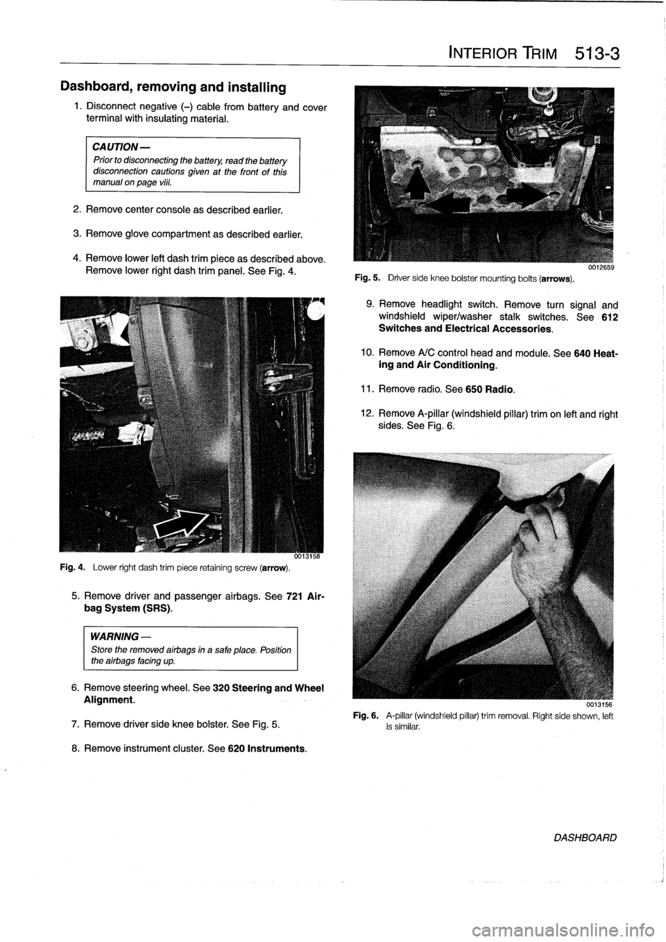
See
Fig
.
4
.
Fig
.
4
.
Lower
right
dash
trim
piece
retaining
screw
(arrow)
.
WARNING
-
Store
the
removed
airbags
in
a
safe
place
.
Position
the
airbags
facing
up
.
8
.
Remove
instrument
cluster
.
See
620
Instruments
.
5
.
Remove
driver
and
passenger
airbags
.
See
721
Air-
bag
System
(SRS)
.
6
.
Remove
steering
wheel
.
See
320
Steering
and
Wheel
Alignment
.
INTERIOR
TRIM
513-
3
Fig
.
5
.
Driver
side
knee
bolster
mounting
bolts
(arrows)
.
9
.
Remove
headlight
switch
.
Remove
turn
signal
and
windshield
wiper/washer
stalk
switches
.
See612
Switches
and
Electrical
Accessories
.
10
.
Remove
A/C
control
head
and
module
.
See
640
Heat-ing
and
Air
Conditioning
.
11
.
Remove
radio
.
See650
Radio
.
12
.
Remove
A-pillar
(windshield
pillar)
trim
on
left
and
right
sides
.
See
Fig
.
6
.
UU13156
Fig
.
6
.
A-pillar
(windshield
pillar)
trim
removal
.
Right
side
shown,
left
7
.
Remove
driver
side
knee
bolster
.
See
Fig
.
5
.
is
similar
.
DASHBOARD
Page 348 of 759
513-
4
INTERIOR
TRIM
13
.
Remove
reinforcement
bar
below
steering
column
and
remove
steering
column
shear
bolts
.
Lower
steering
only
slightly
and
support
steering
column
.
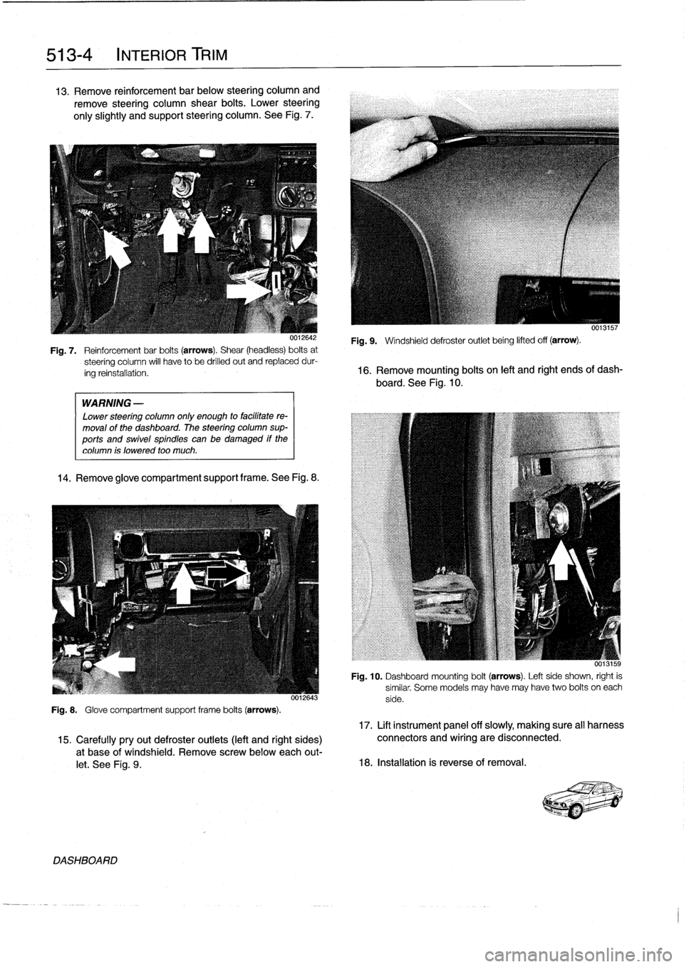
See
Fig
.
7
.
WARNING
-
Lower
steering
column
only
enough
to
facilitate
re-
moval
of
the
dashboard
.
The
steering
column
sup-
ports
and
swivel
spindles
canbe
damaged
if
the
column
is
lowered
too
much
.
14
.
Remove
glove
compartment
support
frame
.See
Fig
.
8
.
0012643
Fig
.
8
.
Glove
compartment
support
frame
bolts
(arrows)
.
DASHBOARD
0013157
Fig
.
9
.
Windshield
defroster
outlet
being
lifted
off
(arrow)
.
Fig
.
7
.
Reinforcementbar
bolts
(arrows)
.
Shear
(headless)
bolts
at
steering
column
will
have
to
be
drilled
out
and
replaceddur-
ing
reinstallation
.
16
.
Remove
mounting
bolts
on
left
and
right
ends
of
dash-
board
.
See
Fig
.
10
.
Fig
.
10
.
Dashboard
mounting
bolt
(arrows)
.
Left
side
shown,
right
is
similar
.
Some
models
may
have
may
have
two
bolts
oneach
side
.
17
.
Lift
instrument
panel
off
slowly,
making
sure
all
harness
15
.
Carefullypryout
defroster
outlets
(left
and
right
sides)
connectors
and
wiring
are
disconnected
.
a
t
base
of
windshield
.
Remove
screwbelow
each
out-
let
.
See
Fig
.
9
.
18
.
Installation
is
reverse
of
removal
.
Page 356 of 759
515-8
CENTRAL
LOCKING
AND
ANTI-THEFT
Central
Body
Electronics
(ZKE
IV)
Electronic
Immobilization
System
(EWS)
Beginning
withvehicles
produced
9193
(model
year
1994),
The
electronic
anti-theft
system
known
as
EWS
was
first
in-
the
centrallocking
system
was
integrated
with
sunroof
and
troduced
in
January
1994
.
The
early
version
of
the
system
window
closure
into
the
Central
Body
Electronics
(ZKE
IV)
uses
a
starting
inhibition
module
to
interrupt
the
ignition,
the
(generation
four)
system
.
The
control
module
for
this
system
fuel
injection
and
the
starter
motor
.
This
system
is
activated
ís
mounted
in
front
of
the
glove
compartment
.
and
deactivated
by
the
centrallockíng
system
.
The
control
module
for
the
system
is
installed
under
the
left
side
of
the
Inthis
system
two
microswítches
are
operated
viathe
door
dashboard
.
lock
cylinder
at
both
front
doors
.
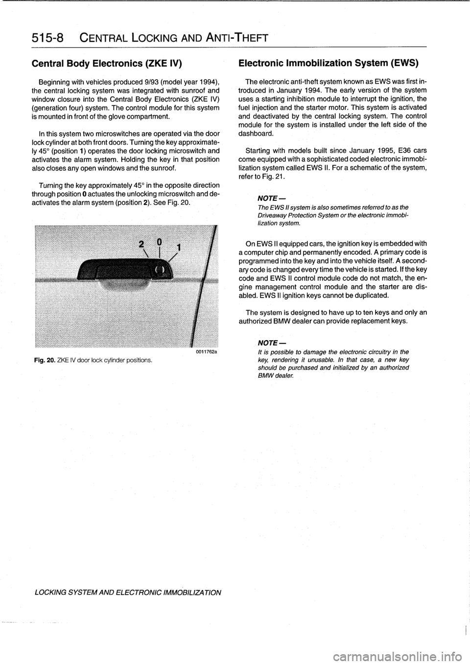
Turning
the
key
approximate-
ly
45°
(position
1)
operates
the
door
locking
microswitch
and
Startingwith
modeis
built
since
January
1995,
E36
cars
activates
the
alarm
system
.
Holding
the
key
in
thatposition
come
equipped
with
a
sophisticated
coded
electronic
immobi
also
closes
any
open
windows
and
the
sunroof
.
lization
system
called
EWS
II
.
Foraschematic
of
the
system,
refer
to
Fig
.
21
.
Turning
the
key
approximately
45°
in
the
opposite
direction
through
position
0
actuates
theunlocking
microswitch
and
de-
activates
the
alarm
system
(position
2)
.
See
Fig
.
20
.
NOTE
-
The
EWS
11
system
is
also
sometimes
referred
to
as
the
Driveaway
Protection
System
or
the
electronic
immobi-
lization
system
.
On
EWS
II
equipped
cars,
the
ignition
key
is
embedded
with
a
computer
chip
and
permanently
encoded
.
A
primary
code
is
programmed
into
the
keyand
finto
the
vehicle
itself
.
A
second-
ary
code
is
changed
every
time
the
vehicle
is
started
.
If
thekey
code
and
EWS
II
control
module
code
do
notmatch,
the
en-
gine
management
control
module
and
the
starter
are
dis-
abled
.
EWS
II
ignition
keyscannot
be
duplicated
.
The
system
is
designed
to
have
up
to
ten
keys
and
only
an
authorized
BMW
dealer
can
provide
replacement
keys
.
j
NOTE-
0011762a
ft
is
possible
to
damage
the
electronic
circuítry
in
the
Fig
.
20
.
ZKE
IV
door
lock
cylinder
positions
.
key,
rendering
if
unusable
.
In
that
case,
a
new
key
shouldbe
purchased
and
initialized
byan
authorized
BMW
dealer
.
LOCKING
SYSTEM
AND
ELECTRONIC
IMM081LIZATION
Page 358 of 759
515-10
CENTRAL
LOCKING
AND
ANTI-THEFT
EWS
II
control
module,
replacing
1
.
Disconnect
negative
(-)
cable
from
battery
.
CAUTION-
Prior
to
disconnecting
the
battery,
read
the
battery
disconnection
cautions
given
at
the
front
of
this
manual
onpage
vüf
.
2
.
Remove
glove
compartment
as
described
in
513
Inte-
rior
Trim
.
3
.
Remove
EWS
II
control
module
harness
connector
.
Pull
module
out
of
bracket
.
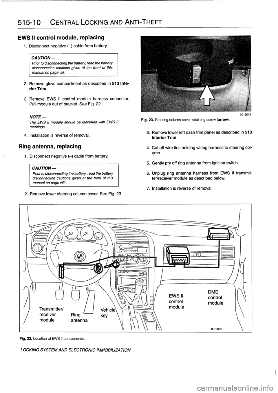
See
Fig
.
22
.
NOTE-
The
EWS
11
module
should
be
identified
with
EWS
11
markings
.
4
.
Installation
is
reverse
of
removal
.
Ring
antenna,
replacing
4
.
Cut
off
wire
ties
holding
wiring
harness
to
steering
col-
umn
.
1
.
Disconnect
negative
(-)
cable
from
battery
.
CAUTION
-
Prior
to
disconnecting
the
battery,
read
the
battery
disconnectioncautionsgiven
at
the
front
of
this
manualonpage
viii
.
2
.
Remove
lower
steering
column
cover
.
See
Fig
.
23
.
Transmitter/
receiver
Ring
r
module
antenna
Fig
.
22
.
Location
of
EWS
II
components
.
LOCKING
SYSTEM
AND
ELECTRONIC
IMMOBILIZATION
Fig
.
23
.
Steering
column
cover
retaining
screw
(arrow)
.
5
.
Gently
pry
off
ring
antenna
from
ignition
switch
.
7
.
Installation
is
reverse
of
removal
.
0012543
3
.
Remove
lower
left
dash
trim
panel
as
described
in
513
Interior
Trim
.
6
.
Unplug
ring
antennaharness
from
EWS
II
transmit-
ter/receiver
module
as
described
below
.
Page 359 of 759
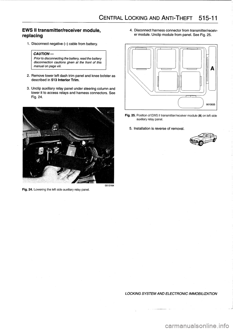
EWS
II
transmitterlreceiver
module,
replacing
1
.
Disconnect
negative
(-)
cable
from
battery
.
CAUTION-
Prior
to
disconnectiog
the
battery,
read
the
battery
disconnection
cautions
given
at
the
front
of
this
manual
onpage
viii
.
2
.
Remove
lower
left
dash
trim
panel
and
knee
bolster
as
described
in
513
Interior
Trim
.
3
.
Unclip
auxiliary
relay
panel
under
steering
column
and
lower
it
to
access
relays
and
harness
connectors
.
See
Fig
.
24
.
Fig
.
24
.
Lowering
the
left
side
auxiliaryrelay
panel
.
CENTRAL
LOCKING
AND
ANTI-THEFT
515-11
0013164
4
.
Disconnect
harness
connector
from
transmitter/receiv-
er
module
.
Unclip
module
from
panel
.
See
Fig
.
25
.
5
.
Installation
is
reverse
of
removal
.
0
A
0013035
Fig
.
25
.
Position
of
EWS
II
transmitter/receiver
module
(A)
on
left
side
auxiliaryrelay
panel
.
LOCKING
SYSTEM
AND
ELECTRONIC
IMMOBILIZATION
Page 373 of 759
KL
30
CONVERTIBLE
BATTERY
(ON
TOP
MOTOR)
UP
DOWN
S2
-I
(ON
TOP
MOTOR)
(IN
TOP
STORAGE
WELL)
S4
E36
AUTOMATIC
CONVERTIBLE
S5
(ON
TRUNK
LOCK)I
TOP
CONTROLMODULE
I
LH
SIDE
TOP
LATCH
DRIVE)
1
M-4
m
í
A
7--
Offi-
Íl
ít~~
ENSOR
H
ARD
T
OP
LOCK
SIGNAL
O
1~~11
:i
q
SIGNAL
TOP
MOTOR
POSITION
SIGNAL
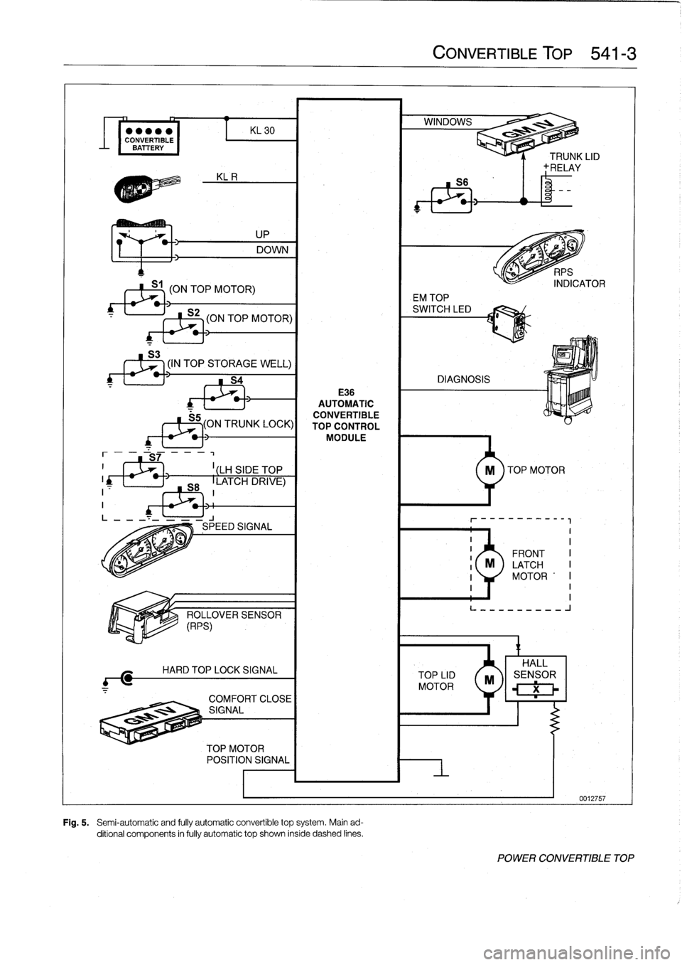
Fig
.
5
.
Semi-automatic
and
fully
automatic
convertible
top
system
.
Main
ad-
ditional
components
in
fully
automatic
top
shown
inside
dashed
lines
.
CONVERTIBLE
TOP
541-3
TOP
LID
MOTOR
EM
TOP
n
~
ll
í
9
.1
-----------
II
II
FRONT
I
M
LATCH
I
1
MOTOR
'I
I
1I
L---------
J
X
POWER
CONVERTIBLE
TOP
Page 379 of 759
Convertible
Top
Lid
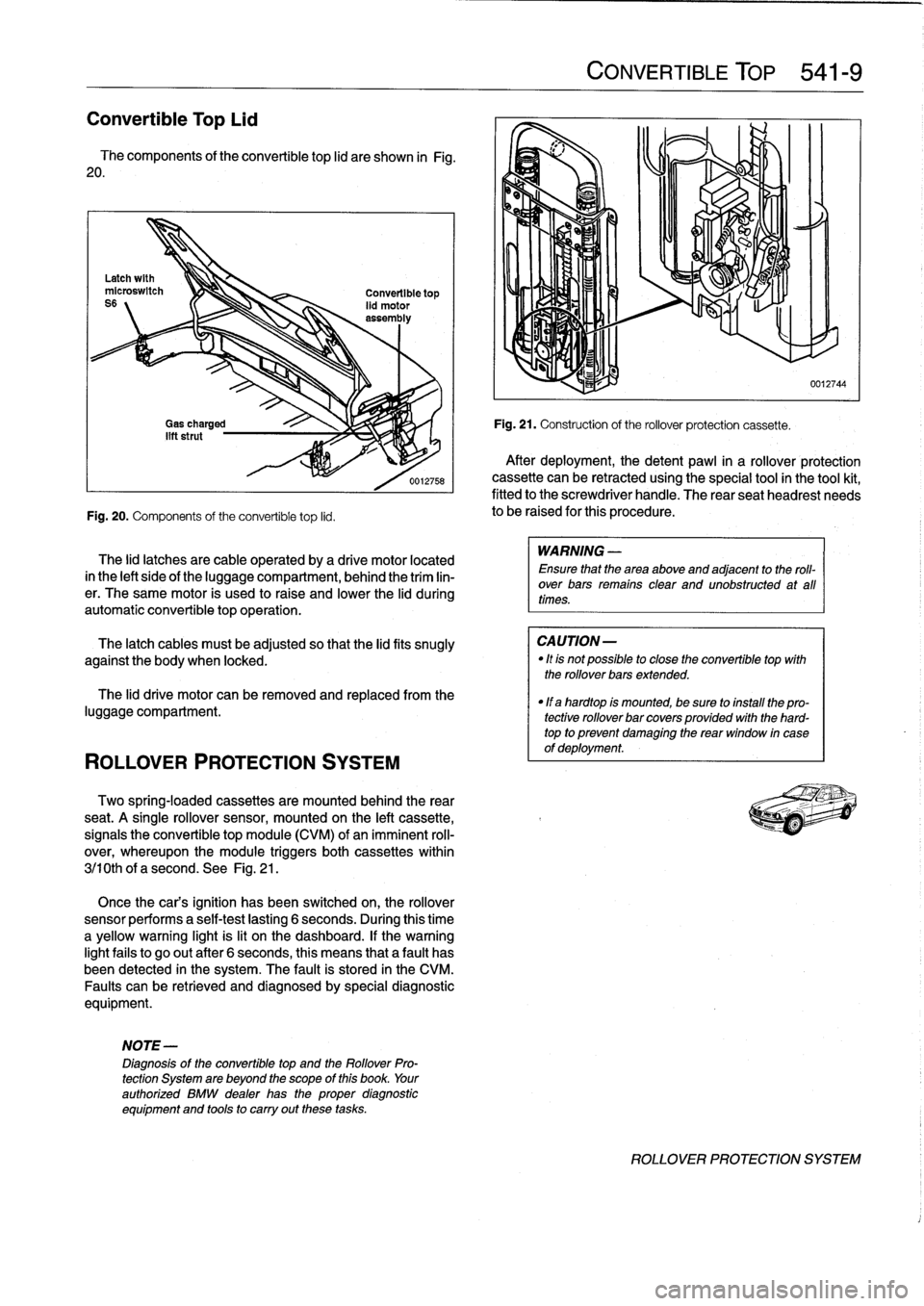
The
components
of
the
convertible
top
lid
are
shown
in
Fig
.
20
.
Fig
.
20
.
Components
of
the
convertible
top
lid
.
ROLLOVER
PROTECTION
SYSTEM
The
lid
latches
are
cable
operated
by
a
drive
motor
located
in
the
left
sideof
the
luggagecompartment,
behind
the
trim
lin-
er
.
The
same
motor
is
used
to
raise
and
lower
the
lid
during
automatic
convertible
topoperation
.
The
latch
cables
must
be
adjusted
so
that
the
lidfits
snugly
against
the
body
when
locked
.
The
lid
drive
motor
can
be
removed
and
replaced
from
the
luggage
compartment
.
Two
spring-locaed
cassettes
are
mounted
behind
the
rear
seat
.
A
single
rollover
sensor,
mounted
on
the
left
cassette,
signals
the
convertible
top
module
(CVM)
of
animminent
roll-
over,
whereupon
the
module
triggers
both
cassettes
within
3j10th
of
a
second
.
See
Fig
.
21
.
Once
the
cars
ignition
has
been
switched
on,
the
rollover
sensor
performs
a
self-test
lasting
6
seconds
.
During
this
time
a
yellow
warning
light
is
lit
on
the
dashboard
.
If
thewarning
lightfails
to
go
out
after
6
seconds,
this
means
that
a
fault
has
been
detected
in
the
system
.
The
fault
is
stored
in
the
CM
Faults
canbe
retrieved
and
diagnosedby
special
diagnostic
equipment
.
NOTE-
Diagnosis
of
the
convertible
top
and
the
Rollover
Pro-
tection
System
are
beyond
the
scope
of
this
book
.
Your
authorized
BMW
dealer
has
the
proper
diagnostic
equipment
and
tools
to
carry
out
these
tasks
.
CONVERTIBLE
TOP
541-
9
Fig
.
21
.
Construction
of
the
rollover
protection
cassette
.
After
deployment,
thedetent
pawl
in
a
rollover
protection
cassette
can
be
retracted
using
the
special
tool
in
the
tool
kit,
fitted
to
the
screwdriver
handle
.
The
rear
seatheadrest
needs
to
be
raised
for
this
procedure
.
WARNING
-
Ensure
that
the
area
above
and
adjacent
to
the
roll-
over
bars
remains
clear
and
unobstructed
at
all
times
.
CAUTION-
"
Itis
not
possible
to
close
the
convertible
top
with
the
rollover
bars
extended
.
"
If
a
hardtop
is
mounted,
be
sure
to
install
the
pro-
tective
rollover
bar
covers
provided
with
the
hard-
top
to
prevent
damaglng
the
rear
window
in
case
of
deployment
.
0012744
ROLLOVER
PROTECTION
SYSTEM
Page 388 of 759
610-2
ELECTRICAL
COMPONENT
LOCATIONS
Fuses
number47
and
50are
mounted
on
the
left
side
splice
panel
.
Refer
lo
Fig
.
5
.
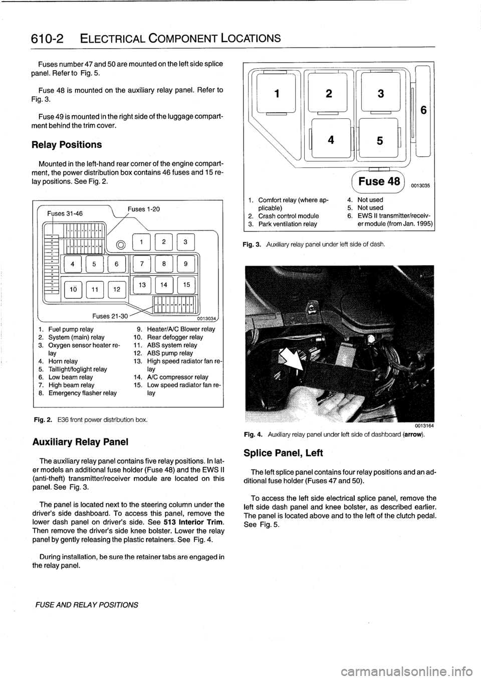
Fuse48
is
mounted
on
the
auxiliary
relay
panel
.
Refer
to
Fig
.
3
.
Fuse
49
is
mounted
in
the
right
side
of
the
luggage
compart-
ment
behind
the
trim
cover
.
Relay
Positions
Mounted
in
the
left-hand
rear
comer
of
the
engine
compart-
ment,
the
power
distribution
box
contains
46
(uses
and
15
re-
lay
positions
.
See
Fig
.
2
.
Fuses31-46
-
Er
a
&QT
MM
~
Fig
.
2
.
E36
front
power
distribution
box
.
FUSE
AND
RELAY
POSITIONS
Fuses1-20
13
EL1
5
]
mmmmmmmmmm
Fuses
21-30
--
0013034)
1
.
Fuel
pump
relay
9
.
Heater/A/C
Blower
relay
2
.
System
(main)
relay
10
.
Rear
defogger
relay
3
.
Oxygen
sensorheater
re-
11
.
ABS
system
relay
lay
12
.
ABS
pump
relay
4
.
Horn
relay
13
.
High
speed
radiator
fan
re-
5
.
Taillight/foglight
relay
]ay
6
.
Low
beam
relay
14
.
A/C
compressor
relay
7
.
High
beam
relay
15
.
Low
speed
radiator
fan
re-
8
.
Emergency
flasherrelay
¡ay
Auxiliary
Relay
Panel
The
auxiliary
relay
panel
contains
five
relay
positions
.
In
lat-
er
modeis
an
additional
fuse
holder
(Fuse48)
and
the
EWS
II
(anti-theft)
transmitter/receiver
module
are
located
on
this
panel
.
See
Fig
.
3
.
The
panel
is
located
nextto
the
steering
column
under
the
driver's
side
dashboard
.
To
access
this
panel,
remove
the
pwer
dash
panel
on
driver's
side
.
See513
Interior
Trim
.
Then
remove
the
driver's
side
knee
bolster
.
Lower
the
relay
panel
by
gently
releasing
the
plastic
retainers
.
See
Fig
.
4
.
During
installation,
be
sure
the
retainer
tabs
are
engaged
in
the
relay
panel
.
Splice
Panel,
Left
3
¡ni
Fig
.
3
.
Auxiliary
relay
panel
under
left
side
of
dash
.
Fuse
48)
0013035
1
.
Comfort
relay
(where
ap-
4
.
Not
used
plicable)
5
.
Not
used
2
.
Crash
control
module
6
.
EWS
II
transmitter/receiv-
3
.
Park
ventilation
relay
er
module
(from
Jan
.
1995)
0013164
Fig
.
4
.
Auxiliary
relay
panel
under
left
sideof
dashboard
(arrow)
.
The
left
splice
panel
contains
four
relay
positions
and
an
ad-
ditional
fuse
holder
(Fuses
47
and
50)
.
To
access
the
left
side
electrical
splice
panel,
remove
the
left
side
dash
panel
and
knee
bolster,
as
described
earlier
.
The
panel
is
located
above
and
lo
the
left
of
the
clutch
pedal
.
See
Fig
.
5
.
Page 389 of 759
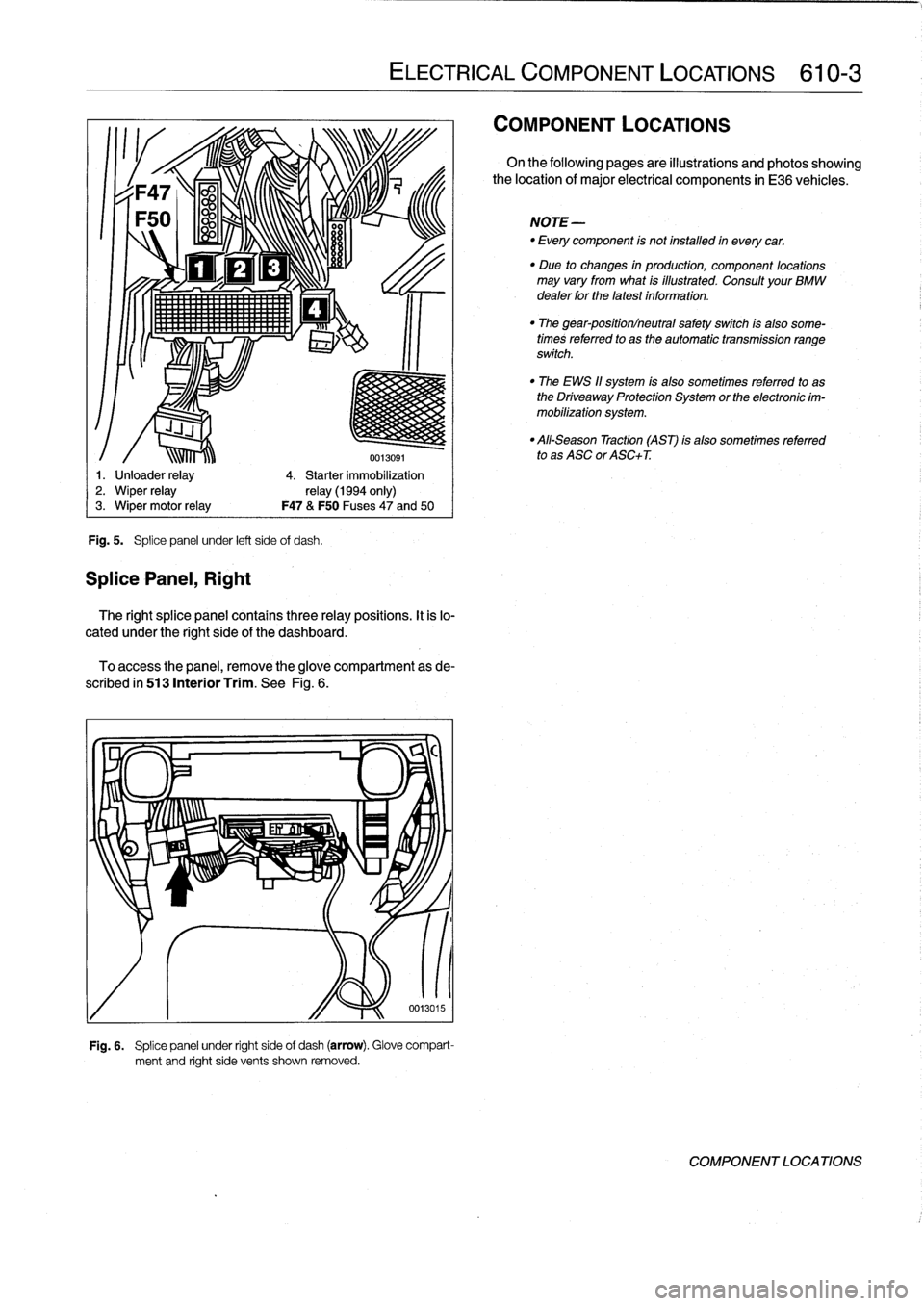
Fig
.
5
.
Splice
panel
under
left
side
of
dash
.
SplicePanel,
Right
ir1!
1,
111lí~lll
.
'
ELECTRICAL
COMPONENT
LOCATIONS
610-3
0013091
1
.
Unloader
relay
4
.
Starter
immobilization
2
.
Wiper
relay
relay
(1994
only)
3
.
Wiper
motor
relay
F47
&
F50
Fuses47
and
50
The
right
splice
panel
contains
three
relay
positions
.
It
is
lo-
cated
under
the
right
side
of
the
dashboard
.
To
access
the
panel,
remove
theglove
compartment
as
de-
scribed
in
513
Interior
Trim
.
See
Fig
.
6
.
Fig
.
6
.
Splice
panel
under
right
side
of
dash
(arrow)
.
Glove
compart-
ment
and
right
side
vents
shown
removed
.
COMPONENT
LOCATIONS
On
the
following
pages
are
illustrations
and
photos
showing
the
location
of
major
electrical
components
in
E36
vehicles
.
NOTE-
-
Every
component
is
not
installed
in
everycar
.
"
Due
to
changes
in
production,
component
locations
may
vary
from
what
is
illustrated
.
Consult
your
BMW
dealer
for
the
latest
information
.
"
The
gear-position/neutral
safety
switch
ís
also
some-
times
referred
to
as
the
automatic
transmission
range
switch
.
"
The
EWS
11
system
is
also
sometimes
referred
to
as
the
Driveaway
Protection
System
or
the
electronic
im-
mobilization
system
.
"
All-Season
Traction
(AST)
is
also
sometimes
referred
to
as
ASC
or
ASC+T
.
COMPONENT
LOCATIONS
Page 390 of 759
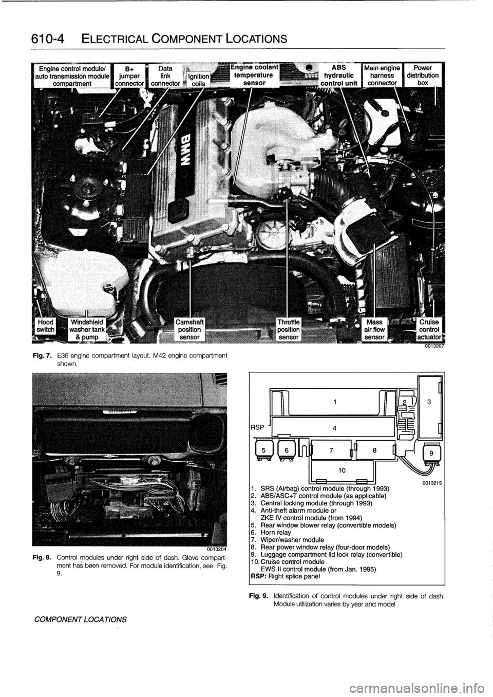
610-4
ELECTRICAL
COMPONENT
LOCATIONS
--J
L
Windshield
washertank
&
pump
Fig
.
7
.
E36
engine
compartment
layout
.
M42
engine
compartment
shown
.
-,x
0013204
Fig
.
8
.
Control
modules
under
right
sideof
dash
.
Glove
compart-
ment
has
been
removed
.
For
module
identification,
see
Fig
.
9
.
COMPONENT
LOCATIONS
RSP
'I
4
ABS
Main
engine
Power
hydraulic
harness
distribution
control
unit
connector
I
box
oe
1
.
SRS
(Airbag)
control
module
(through
1993)
2
.
ABS/ASC+T
control
module
(as
applicable)
3
.
Central
locking
module
(through
1993)
4
.
Anti-theft
alarm
module
or
ZKE
IV
control
module
(from
1994)5
.
Rear
window
blower
relay
(convertible
models)6
.
Horn
relay
7
.
Wiper/washer
module
8
.
Rear
power
window
relay
(four-door
models)9
.
Luggage
compartment
lid
lock
relay
(convertible)
10
.
Cruise
control
module
EWS
II
control
module
(from
Jan
.
1995)
RSP
:
Right
splice
panel
0013215
Fig
.
9
.
Identificationof
control
modules
under
right
side
of
dash
.
Module
utilízation
varies
byyear
andmodel