dash BMW 318i 1995 E36 Owner's Manual
[x] Cancel search | Manufacturer: BMW, Model Year: 1995, Model line: 318i, Model: BMW 318i 1995 E36Pages: 759
Page 396 of 759
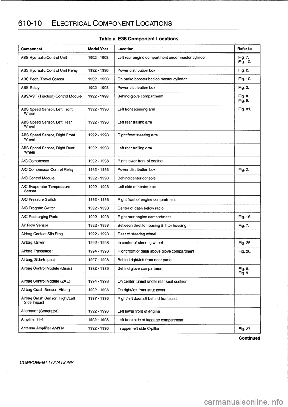
610-10
ELECTRICAL
COMPONENT
LOCATIONS
Component
Model
Year
Location
Refer
to
ABS
Hydraulic
Control
Unit
1992-1998
Left
rear
engine
compartment
undermaster
cylinder
Fig
.
7
.
Fig
.
10
.
ABS
Hydraulic
Control
Unit
Relay
1992-1998
Power
distribution
box
Fig
.
2
.
ABS
Pedal
Travel
Sensor
1992-1998
On
brake
booster
beside
master
cylinder
Fig
.
10
.
ABS
Relay
1992-1998
Power
distribution
box
Fig
.
2
.
ABS/AS
T
(Traction)
Control
Module
1992-1998
Behind
glove
compartment
Fig
.
8
.
Fig
.
9
.
ABS
Speed
Sensor,
Left
Front
1992-1998
Left
front
steering
arm
Fig
.
31
.
Wheel
ABS
Speed
Sensor,
Left
Rear
1992-1998
Left
rear
trailing
arm
Wheel
ABS
Speed
Sensor,
RightFront
11992-1998
Right
front
steering
arm
Wheel
ABS
Speed
Sensor,
Right
Rear
1992-1998
I
Left
rear
trailing
arm
Wheel
1
A/C
Compressor
1
1992-1998
(
Rightlower
frontof
engine
A/C
Compressor
Control
Relay
1
1992-1998
1992-1998
1992-1998
A/C
Control
Module
A/C
Evaporator
Temperature
Sensor
A/C
Pressure
Switch
1992-1998
Right
frontof
engine
compartment
A/C
Program
Switch
1992-1998
Center
of
dash
below
radio
A/CRecharging
Ports
1992-1998
Right
rear
engine
compartment
Fig
.
16
.
Air
Flow
Sensor
1992-1998
Between
throttle
housing
&
filter
housing
Fig
.
7
.
Airbag
Contact
Slip
Ring
1992-1998
Rear
ofsteering
wheel
Airbag,
Driver
1992-1998
In
center
of
steering
wheel
Fig
.
25
.
Airbag,
Passenger
1994-1998
Right
front
of
dash
above
glove
compartment
Fig
.
26
.
Airbag,
Side-Impact
1997-1998
Behind
right/left
front
door
panel
Airbag
Control
Module
(Basic)
1992-1993
Behind
glove
compartment
Fig
.
8
.
Fig
.
9
.
Airbag
Control
Module
(ZAE)
1994-1998
On
center
tunnel
under
rear
seat
cushion
Airbag
Crash
Sensor,
Airbag
1992-1993
On
righUleft
front
strut
tower
Airbag
Crash
Sensor,
Right/Left
1997-1998
Right/left
door
si¡¡
behind
front
seatSide
Impact
Alternator
(Generator)
1992-1998
Left
lowerfront
of
engine
Amplifier
Hi-fi
1992-1998
Left
front
side
of
luggage
compartment
Antenna
Amplifier
AM/FM
1992-1998
In
upper
left
side
C-pillar
Fig
.
27
.
COMPONENT
LOCA
TIONS
Table
a
.
E36
Component
Locations
Power
distribution
box
Fig
.
2
.
Behind
center
console
Left
sideof
heater
box
Continued
Page 397 of 759
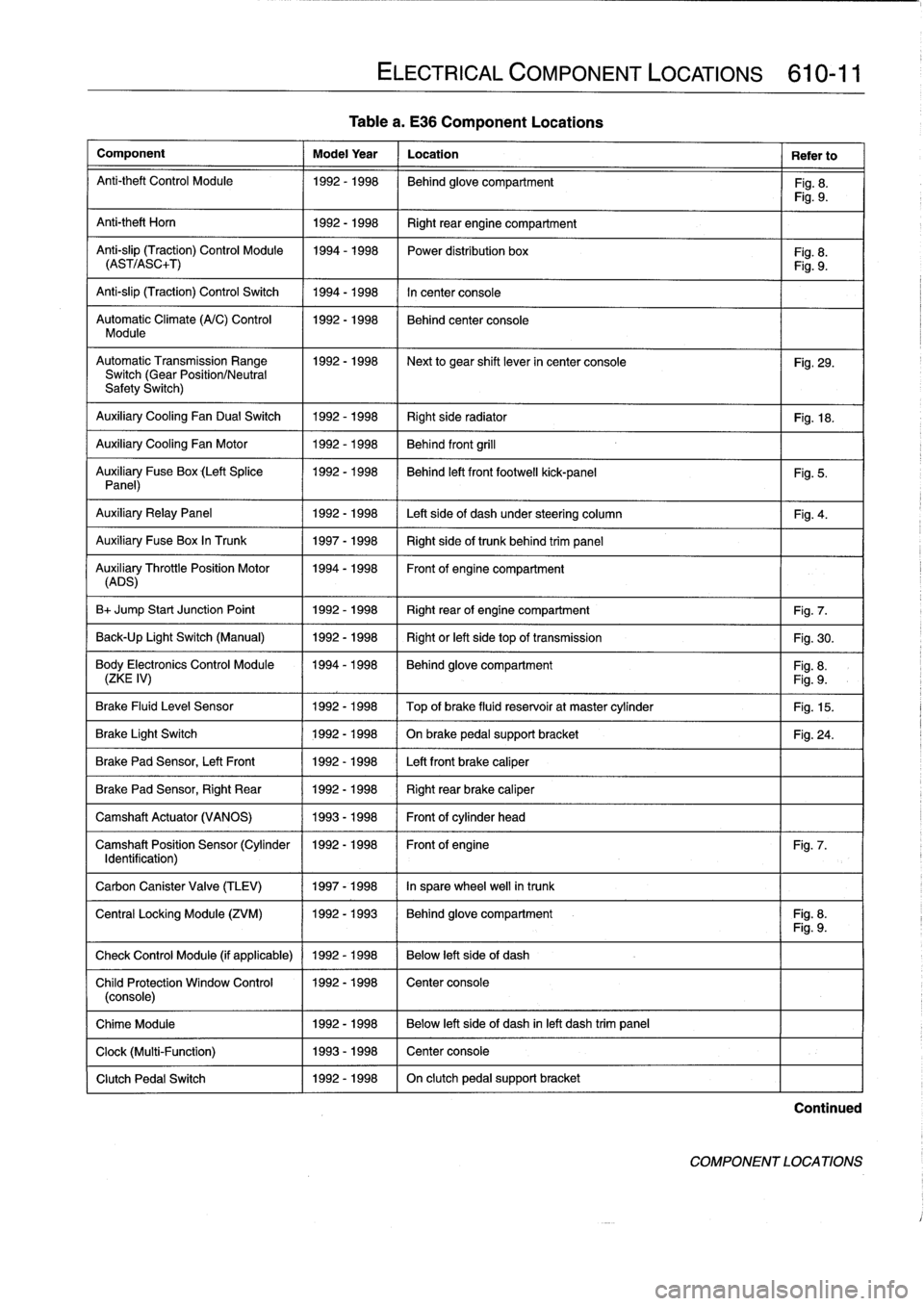
Table
a
.
E36
Component
Locations
Component
Model
Year
Location
Refer
to
Anti-theft
Control
Module
1992-1998
Behind
glove
compartment
Fig
.
8
.
Fig
.
9
.
Anti-theft
Horn
1
1992-1998
1
Right
rear
engine
compartment
Anti-slip
(Traction)
Control
Module
1994-1998
Power
distribution
box
Fig
.
8
.
(AST/ASC+T)
Fig
.
9
.
Anti-slip
(Traction)
Control
Switch
1994-1998
In
center
console
Automatic
Climate
(A/C)
Control
1992-1998
Behind
center
console
Module
AutomaticTransmission
Range
1992-1998
~
Next
to
gear
shift
lever
in
center
console
Fig
.
29
.
Switch
(Gear
Position/Neutral
Safety
Switch)
Auxiliary
Cooling
Fan
Dual
Switch
1992-1998
Right
side
radiator
1
Fig
.
18
.
Auxiliary
Cooling
Fan
Motor
1992-1998
Behind
front
grill
Auxiliary
Fuse
Box
(Left
Splice
1992-1998
I
Behind
left
front
footwell
kick-panel
Panel)
Auxiliary
RelayPanel
1
1992-1998
1
Left
side
of
dash
under
steering
column
Auxiliary
Fuse
Box
In
Trunk
1
1997-1998
1
Right
sideof
trunk
behind
trim
panel
AuADSry
ThrottlePosition
Motor
11994-1998
Front
of
engine
compartment
B+
Jump
Start
Junction
Point
1992-1998
Right
rear
of
engine
compartment
Fig
.
7
.
Back-Up
Light
Switch
(Manual)
1992-1998
Right
or
left
side
top
of
transmission
Fig
.
30
.
Body
Electronics
Control
Module
1994-1998
Behindglove
compartment
Fig
.
8
.
(ZKE
IV)
Fig
.
9
.
Brake
Fluid
Level
Sensor
1992-1998
Top
of
brake
fluid
reservoir
at
master
cylinder
Fig
.
15
.
Brake
Light
Switch
1
1992-1998
1
On
brake
pedal
supportbracket
Brake
Pad
Sensor,
Left
Front
1
1992-1998
1
Left
front
brake
caliper
Brake
Pad
Sensor,
Right
Rear
1992-1998
Right
rear
brake
caliper
Camshaft
Actuator
(VANOS)
1993-1998
Front
of
cylinder
head
Camshaft
Position
Sensor
(Cylinder
1992-1998
Front
of
engine
Identification)
Carbon
Canister
Valve
(TLEV)
1
1997-1998
1
In
sparewheel
well
in
trunk
ELECTRICAL
COMPONENT
LOCATIONS
610-11
Fig
.
5
.
Fig
.
4
.
Fig
.
24
.
Fig
.
7
.
Central
Locking
Module
(ZVM)
11992-1993
1
Behindglove
compartment
I
Fig
.
8
.
Fig
.
9
.
Check
Control
Module
(if
applicable)
1
1992
-
1998
1
Below
left
side
of
dash
Child
Protection
Window
Control
1992-1998
Center
console
(console)
Chime
Module
1992-1998
Below
left
side
of
dash
inleft
dash
trim
panel
Clock
(Multi-Function)
1993-1998
Center
console
Clutch
Pedal
Switch
1992-1998
On
clutch
pedal
support
bracket
Continued
COMPONENT
LOCATIONS
Page 400 of 759
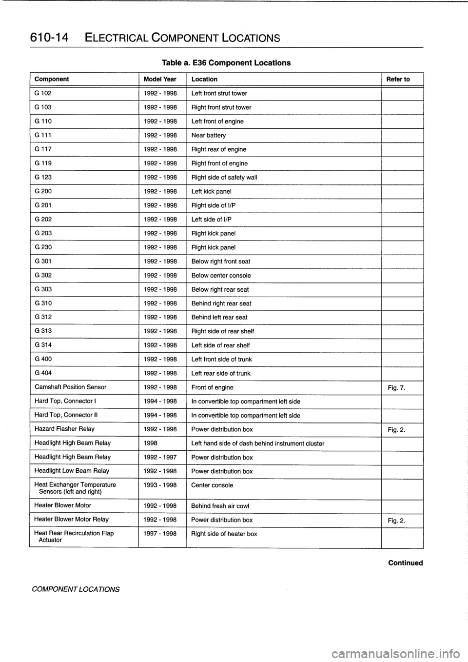
610-14
ELECTRICAL
COMPONENT
LOCATIONS
Component
Model
Year
Location
Refer
to
G
102
1992-1998
Left
front
strut
tower
G
103
1992-1998
Right
front
strut
tower
G
110
1992-1998
Left
front
of
engine
G
111
1992-1998
Near
battery
G
117
1992-1998
Right
rearof
engine
G
119
1992-
1998
Right
front
of
engine
G
123
1992-1998
Right
side
of
safety
wall
G
200
1992-1998
Left
kick
panel
G
201
1992-1998
Right
side
ofI/P
G
202
1992-1998
Left
side
ofI/P
G
203
1992-1998
Right
kick
panel
G
230
1992-1998
Right
kick
panel
G
301
1992-1998
Below
rightfront
seat
G
302
1992-1998
Below
center
console
G
303
1992-1998
Below
right
rear
seat
G
310
1992-1998
Behind
right
rear
seat
G
312
1992-1998
Behind
left
rear
seat
G
313
1992-1998
Right
side
of
rear
shelf
G
314
1992-1998
Left
side
of
rear
shelf
G
400
1992-1998
Left
front
side
of
trunk
G
404
1992-1998
Left
rearside
of
trunk
Camshaft
Position
Sensor
1992-1998
Front
of
engine
Fig
.
7
.
Hard
Top,
Connector
1
1994-1998
In
convertible
top
compartment
left
side
Hard
Top,
Connector
II
1994-1998
In
convertible
top
compartment
left
side
Hazard
Flasher
Relay
1992-1998
Power
distribution
box
Fig
.
2
.
Headlight
High
Beam
Relay
1998
Left
hand
side
of
dash
behind
instrument
cluster
Headlight
High
Beam
Relay
1992-1997
Power
distribution
box
Headlight
Low
Beam
Relay
1992-1998
Power
distribution
box
Heat
ExchangerTemperature
1993-1998
Center
console
Sensors
(left
and
right)
HeaterBlower
Motor
1992-1998
Behind
fresh
air
cowl
HeaterBlower
Motor
Relay
1992-1998
Power
distribution
box
Fig
.
2
.
Heat
Rear
Recirculation
Flap
1997-1998
Right
sideof
heater
box
Actuator
COMPONENTLOCATIONS
Tablea
.
E36
Component
Locations
Continued
Page 401 of 759
Component
Model
Year
Location
Refer
to
Heater
Recirculation
Flap
Actuator
1992-1998
Below
left
dash
right
side
of
steering
column
HeaterBlowerMotor
Resistor
Pack
1992-1998
Behind
center
of
dashboard
Heater
Regulator
FlapActuator
1997-1998
Right
side
of
heater
box
HeaterValve
Assembly
1992-1998
Left
rear
engine
compartment
HeatingNentilation
Relay
Box
1992-1993
Below
left
side
of
dash
HeatingNentilation
Relay
1994-1998
Left
front
footwell
High
Speed
Cooling
Fan
Relay
1992-1998
Power
distribution
box
Fig
.
2
.
Homs,
Right/Left
1993-1998
Front
of
engine
compartment
Horn
Relay
1992-1998
Power
distribution
box
Fig
.
2
.
Horn
Relay
(Alpine)
1994-1998
Behind
glove
compartment
Fig
.
8
.
Board
Computer/Anti-Theft
Fig
.
9
.
Idle
Speed
Control
Valve
1992-1995
Top
rearof
enginebehind
intake
manifold
(M42
engine)
Fig
.
11
.
Idle
Speed
Control
Valve
1992-1995
Top
left
side
of
engine
(M50
engine)
Idle
Speed
Control
Valve
1993-1996
Below
intake
manifold
(M50/S50US
engine)
Idle
Speed
Control
Valve
1996-1998
On
throttle
housing
(M44
engine)
Fig
.
15
.
Idle
Speed
Control
Valve
1997-1998
Left
front
of
engine
below
intake
manifold
(M52/S52US
engine)
Ignition
Coils
1992-1998
Right
of
engineunder
plastic
cover
(four-cylinder)
Fig
.
7
.
Ignition
Cofs
1992-1998
Top
of
engine
undercover
(six-cylinder)
Fig
.
17
.
Ignition
Switch
1992-1998
Right
sídeofsteering
column
Intake
Air
Resonance
Changeover
1992-1998
Leftrear
of
engine
compartment
Valve(DISA)
Intake
Air
Temperature
Sensor
1992-1995
In
mass
air
flow
sensor
(M42
engine)
Intake
Air
TemperatureSensor
1996-1998
In
top
ofair
filter
housing
(M44
engine)
Fig
.
12
.
Intake
Air
Temperature
Sensor
1992-1998
I
Left
sídeof
engine
in
intake
manifold
(six-cylinder)
-
-
I
Fig
.
13
.
Fig
.
14
.
Kick-Down
Switch
(A/T)
1
1992-1998
1
Left
footwell
Mixing
Actuators
1
1992-1998
1
Heater
box
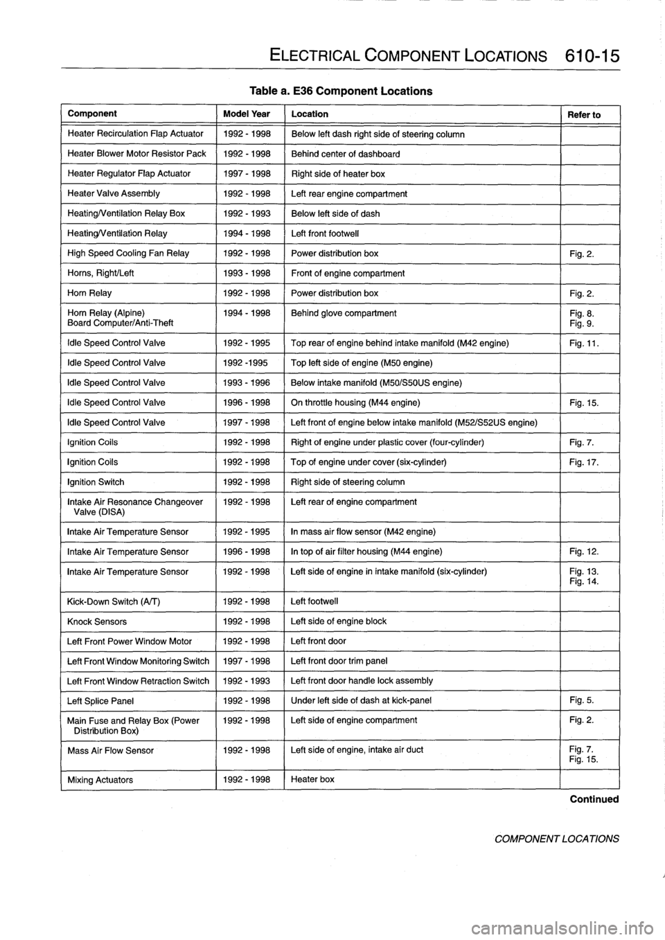
ELECTRICAL
COMPONENT
LOCATIONS
610-15
Table
a
.
E36
Component
Locations
Knock
Sensors
1
1992-1998
1
Left
side
of
engine
block
Left
Front
Power
Window
Motor
11992-1998
/
Left
front
door
Left
Front
Window
Monitoring
Switch
1
1997-1998
1
Left
front
door
trim
panel
Left
Front
Window
Retraction
Switch
1
1992
-
1993
1
Left
front
door
handle
lock
assembly
Left
Splice
Panel
1
1992-1998
1
Under
left
side
of
dash
at
kick-panel
1
Fig
.
5
.
Main
Fuse
and
Relay
Box
(Power
1992-1998
I
Left
sideof
engine
compartment
Fig
.
2
.
Distribution
Box)
1
I
Mass
Air
Flow
Sensor
1992-1998
I
Left
side
of
engine,
intake
air
duct
Fig
.
7
.1
I
Fig
.
15
.
Continued
COMPONENT
LOCATIONS
Page 403 of 759
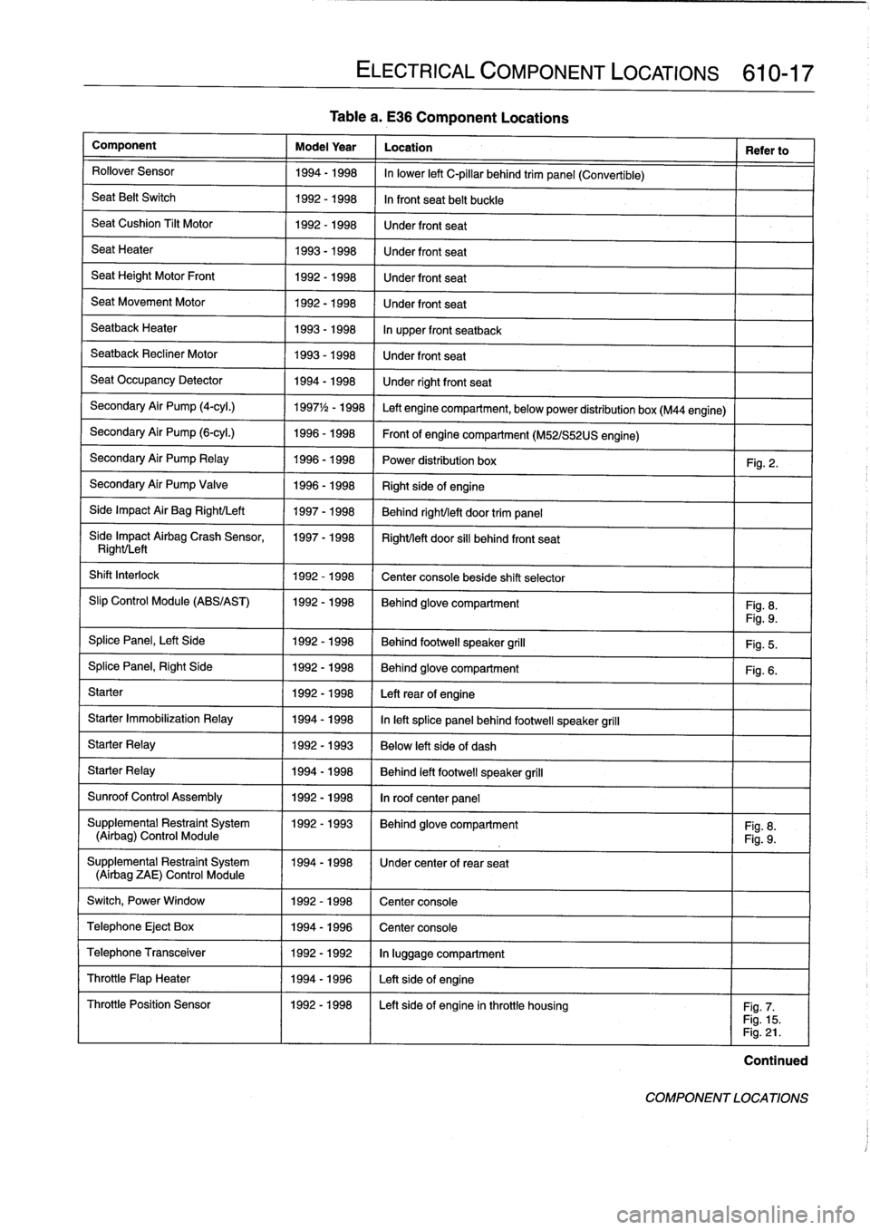
Tablea
.
E36
Component
Locations
Component
Model
Year
Location
Refer
to
Rollover
Sensor
1994-1998
In
lower
left
C-pillar
behind
trim
panel
(Convertible)
Seat
Belt
Switch
1992-1998
In
front
seat
belt
buckle
SeatCushion
Tilt
Motor
1992-1998
Under
front
seat
Seat
Heater
1993-1998
Under
front
seat
Seat
Height
Motor
Front
1992-1998
Under
front
seat
Seat
Movement
Motor
1992-1998
Under
front
seat
Seatback
Heater
1993-1998
In
upper
front
seatback
Seatback
Recliner
Motor
1993-1998
Under
front
seat
Seat
Occupancy
Detector
1994-1998
Under
rightfront
seat
Secondary
Air
Pump
(4-cyl
.)
1997
1
/2
-
1998
Left
engine
compartment,
belowpower
distribution
box
(M44
engine)
Secondary
Air
Pump
(6-cyl
.)
1996-1998
Front
of
engine
compartment
(M52/S52US
engine)
Secondary
Air
Pump
Relay
1996-1998
Power
distribution
box
Fig
.
2
.
Secondary
Air
Pump
Valve
1996-1998
Right
sideof
engine
Side
Impact
Air
Bag
Right/Left
1997-1998
Behind
right/left
door
trim
panel
Síde
Impact
Airbag
Crash
Sensor,
1997-1998
Right/left
door
si¡¡
behind
front
seat
Right/Left
Shift
Interlock
1992-1998
Center
console
beside
shift
selector
Slip
Control
Module
(ABS/AST)
1992-1998
Behind
glove
compartment
Fig
.
8
.
Fig
.
9
.
Splice
Panel,
Left
Side
1992-1998
Behind
footwell
speaker
grill
Fig
.
5
.
SplicePanel,
Right
Side
1992-1998
Behind
glove
compartment
Fig
.
6
.
Starter
1992-1998
Leftrear
of
engine
Starter
Immobilization
Relay
1994-1998
In
left
splice
panelbehind
footwell
speaker
grill
Starter
Relay
1992-1993
Below
left
side
of
dash
Starter
Relay
1994-1998
Behind
left
footwell
speaker
grill
Sunroof
Control
Assembly
1992-1998
In
roof
center
panel
Supplemental
Restraint
System
11992-1993
I
Behind
glove
compartment
I
Fig
.
8
.
(Airbag)
Control
Module
Fig
.
9
.
Supplemental
Restraint
System
1994-1998
1
Under
center
of
rear
seat
(Airbag
ZAE)
Control
Module
Switch,
Power
Window
1
1992-1998
1
Center
console
Telephone
Eject
Box
1
1994-1996
1
Center
console
ELECTRICAL
COMPONENT
LOCATIONS
610-17
Telephone
Transceiver
1992-1992
In
luggage
compartment
Throttle
Flap
Heater
1994-1996
Left
sideof
engine
Throttle
Position
Sensor
1992-1998
I
Left
sideof
engine
inthrottle
housing
I
Fig
.
7
.
Fig
.
15
.
Fig
.
21
.
Continued
COMPONENT
LOCATIONS
Page 432 of 759
612-4
SWITCHES
AND
ELECTRICAL
ACCESSORIES
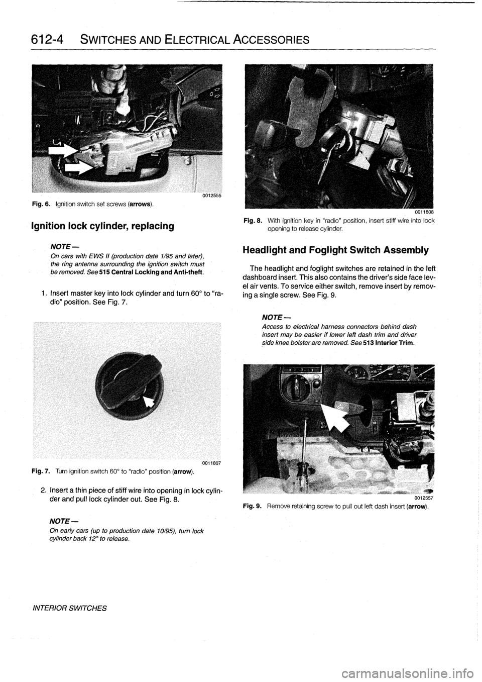
Fig
.
6
.
Ignition
switch
set
screws
(arrows)
.
Ignition
lock
cylinder,
replacing
NOTE-
On
cars
with
EWS
11(production
date
1/95
and
later),
the
ring
antenna
surrounding
the
ignition
switch
must
be
removed
.
See
515
Central
Locking
and
Anti-theft
.
1
.
Insert
master
key
finto
lock
cylinder
and
turn
60°
to
"ra-
dio"
position
.
See
Fig
.
7
.
Fig
.
7
.
Turn
ignition
switch
60°
to
"radio"
position
(arrow)
.
2
.
Insert
a
thin
piece
of
stiff
wire
into
opening
in
lock
cylin-
der
and
pull
lockcylinder
out
.
See
Fig
.
8
.
NOTE-
On
early
cars
(up
to
production
date
1ol95),
turn
lock
cylinder
back
12°
to
release
.
INTERIOR
SWITCHES
0012555
0011807
0011808
Fig
.
8
.
With
ignition
key
in
"radio"position,
insert
stiff
wire
into
lock
opening
to
release
cylinder
.
Headlight
and
Foglight
Switch
Assembly
The
headlight
and
foglight
switches
are
retained
in
the
left
dashboard
insert
.
This
alsocontains
the
driver's
side
face
lev-
e¡
air
vents
.
To
service
either
switch,
remove
insert
byremov-
ing
a
single
screw
.
See
Fig
.
9
.
NOTE-
Access
to
electrical
hamess
connectors
behind
dash
insert
may
be
easier
if
lower
left
dash
trim
and
driverside
knee
bolsterare
removed
.
See
513
Interior
Trim
.
Fig
.
9
.
Remove
retaíning
screw
to
pull
out
left
dash
insert
(arrow)
.
Page 433 of 759
Headlight
switch,
replacing
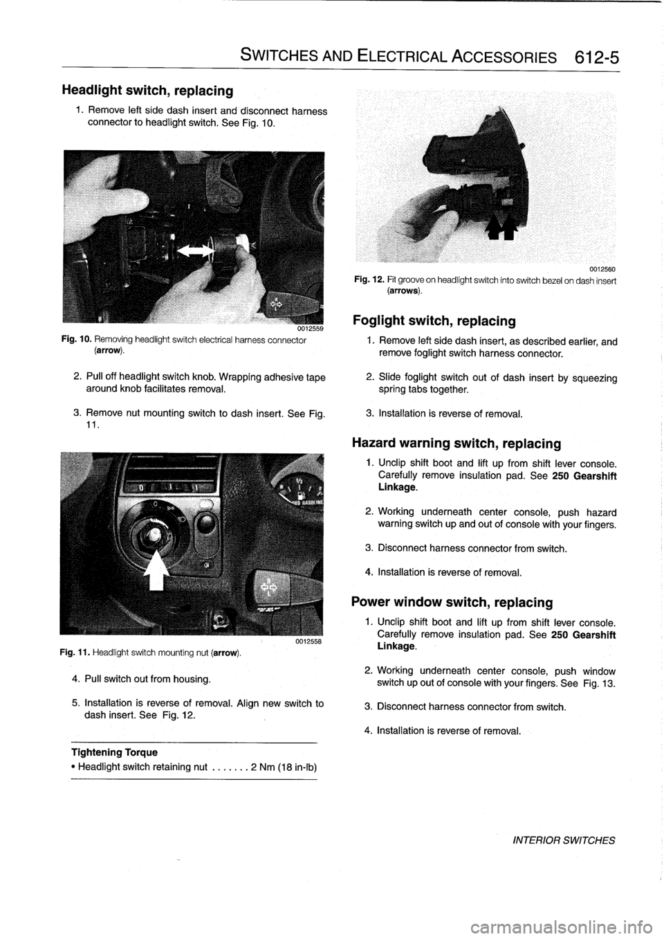
1
.
Remove
left
side
dash
insert
and
disconnect
harness
connector
to
headlight
switch
.
See
Fig
.
10
.
3
.
Remove
nut
mounting
switch
to
dash
insert
.
See
Fig
.
11
.
Fig
.
11
.
Headlight
switch
mounting
nut
(arrow)
.
4
.
Pull
switch
out
from
housing
.
SWITCHES
AND
ELECTRICAL
ACCESSORIES
612-5
0012558
5
.
Installation
is
reverse
of
removal
.
Align
new
switch
to
dash
insert
.
See
Fig
.
12
.
Tightening
Torque
"
Headlight
switch
retaining
nut
.
......
2
Nm
(18
in-lb)
Foglight
switch,
replacing
0012559
Fig
.
10
.
Removing
headlightswitch
electrical
harness
connector
1
.
Remove
left
side
dash
insert,
as
described
earlier,
and
(arrow)
.
remove
foglight
switch
harness
connector
.
2
.
PA
off
headlight
switch
knob
.
Wrapping
adhesive
tape
aroundknob
facilitates
removal
.
spring
tabs
together
.
0012560
Fig
.
12
.
Fit
groove
on
headlightswitch
into
switch
bezel
ondash
insert
(arrows)
.
2
.
Slide
foglight
switch
out
of
dash
insert
by
sqúeezing
3
.
Installation
is
reverse
of
removal
.
Hazard
warning
switch,
replacing
1
.
Unclip
shift
boot
and
lift
up
from
shift
lever
console
.
Carefully
remove
insulation
pad
.
See
250
Gearshift
Linkage
.
2
.
Working
underneath
center
console,
push
hazard
warning
switch
up
and
out
of
console
with
your
fingers
.
3
.
Disconnect
harness
connector
from
switch
.
4
.
Installation
is
reverse
of
removal
.
Power
window
switch,
replacing
1
.
Unclip
shift
boot
and
lift
up
from
shift
lever
console
.
Carefully
remove
insulation
pad
.
See250
Gearshift
Linkage
.
2
.
Working
underneath
center
console,
push
window
switch
up
out
of
console
with
your
fingers
.
See
Fig
.
13
.
3
.
Disconnect
harness
connector
from
switch
.
4
.
Installation
is
reverse
of
removal
.
INTERIOR
SWITCHES
Page 437 of 759
INSTRUMENT
CLUSTER
....
.
.
.
.
.
...
.
..
620-1
Instrument
cluster,
seif-testing
.
.
.......
.
..
620-1
Instrument
cluster,
removing
and
installing
...
620-1
Instrument
cluster
bulbs,
replacing
.
.
.
.
.
.
...
620-2
GENERAL
This
repair
group
covers
removal
and
installation
of
the
in-
strument
cluster
and
the
Multi-information
Display
(MID)
mod-
ule
.
Bulb
replacement
information
for
these
units
is
also
included
here
.
NOTE
-
A
quick
check
of
the
temperature
gauge
and
its
electri-
cal
circuitis
given
in
170
Radiator
and
Cooling
Sys-
tem
.
Use
this
procedure
to
diagnosea
faulty
temperature
gauge
INSTRUMENT
CLUSTER
When
servicing
the
instrument
cluster,
always
disconnect
the
negative
(-)
cable
from
the
battery
and
insulate
the
cable
end
to
prevent
accidental
re-connection
.
Instrument
cluster,
seif-testing
Severa¡
different
versions
of
the
basic
instrument
cluster
havebeen
fitted
in
E36
cars
.
It
is
possibleto
perform
an
instru-
ment
cluster
test
and
display
system
test
information
.
Some
of
the
information
displayed
by
the
instrument
cluster
during
seif-testing
is
used
for
interna¡
BMW
organizationpur-
poses,
suchasmatching
the
correct
instrument
cluster
com-
ponents
during
parts
replacement
.
Other
functions
test
the
various
instrument
modules
.
Self-test
is
also
used
to
recode
the
instrument
cluster
after
removal
.
In
later
production
vehicles
(1996
and
later)
the
test
results
canbe
downioaded,
via
the
diagnostic
plug,
byan
authorized
BMW
dealertechnician
.
1
.
Turn
ignition
to
"radio"position
.
2
.
Press
and
hold
reset
button
on
trip-odometer
untiltrip-
odometer
display
shows
numerical
codes
.
620
Instruments
4
.
Turn
off
ignition
.
Instrument
cluster,
removing
and
installing
INSTRUMENTS
620-1
GENERAL
.....
.
.
.
.
.
.
.
.
.
.........
.
....
620-1
Odometer
coding
plug,
replacing
.....
.
.
.
.
.
.
620-2
Vehicle
speed
sender,
replacing
...
.
.
.
.
.
.
.
.
620-3
MULTI-INFORMATION
DISPLAY
(MID)
.
.
.
620-4
Multi-Information
Display,
removing
and
installing
..
.
....
.
.........
620-4
3
.
With
each
subsequent
press
of
the
button,
a
different
function
is
tested
.
Some
functions
will
activate
need1e
gauges
.
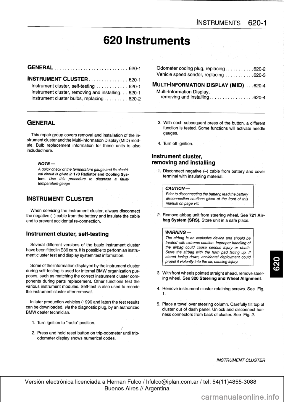
1
.
Disconnect
negative
(-)
cable
from
battery
and
cover
terminal
with
insulating
material
.
CAUTION-
Prior
to
disconnectiog
the
battery,
read
the
battery
disconnection
cautionsgiven
at
the
front
of
this
manual
on
page
vi¡¡
.
2
.
Remove
airbag
unit
from
steering
wheel
.
See
721
Air-
bag
System
(SRS)
.
Store
unit
in
a
safe
place
.
WARNING
-
The
airbag
is
an
explosive
devfce
and
should
be
treated
with
extreme
caution
.
Improper
handling
of
the
airbag
could
cause
serious
injury
or
death
.
Store
the
airbag
with
the
horn
pad
facing
up
.
If
stored
facing
down,
accidental
deployment
couldpropel
it
vfolently
into
the
air,
causing
injury
.
3
.
With
front
wheels
pointed
straight
ahead,
remove
steer-
ing
wheel
.
See
320
Steering
and
Wheel
Alignment
.
4
.
Remove
instrument
cluster
retaining
screws
.
See
Fig
.
1
.
5
.
Place
a
towel
over
steering
column
.
Carefully
tilt
top
of
cluster
out
of
dash
panel
.
Unlock
and
disconnect
har-
ness
connectors
from
back
of
cluster
.
See
Fig
.
2
.
INSTRUMENT
CLUSTER
Page 440 of 759
620-
4
INSTRUMENTS
MULTI-INFORMATION
DISPLAY
(MID)
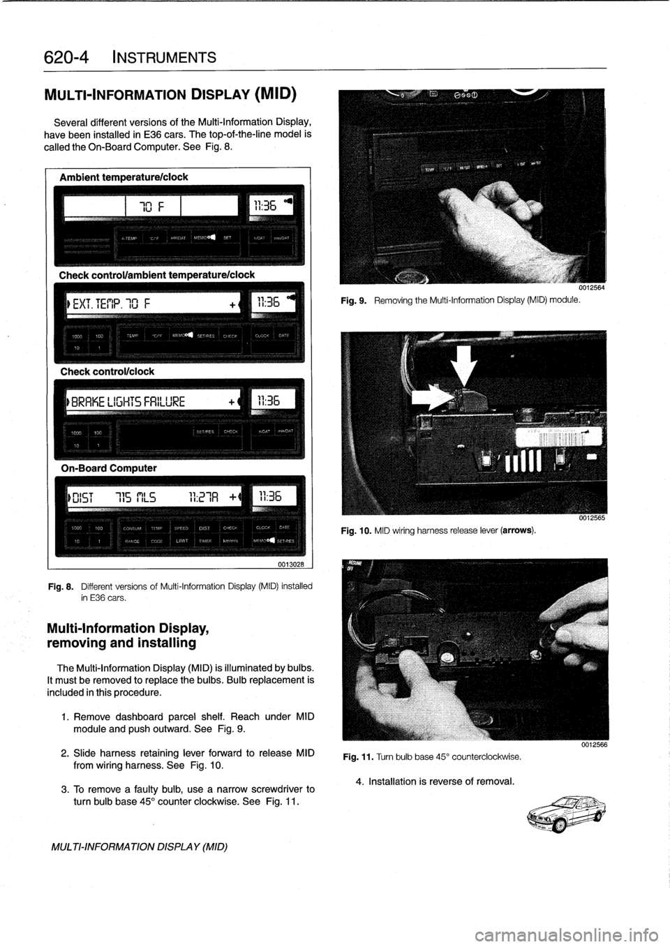
Severa¡
different
versionsof
the
Multi-Information
Display,
have
been
installed
in
E36
cars
.
The
top-of-the-line
model
is
called
the
Oh-BoardComputer
.
See
Fig
.
8
.
Ambient
temperature/ciock
Check
control/clock
0013028
Fig
.
8
.
Different
versions
of
Multi-Information
Display
(MID)
installed
in
E36
cars
.
Multi-Information
Display,
removing
and
installing
The
Multi-Information
Display
(MID)
is
illuminated
by
bulbs
.
It
mustbe
removed
to
replace
the
bulbs
.
Bulb
replacement
is
included
in
this
procedure
.
1
.
Remove
dashboard
parcel
shelf
.
Reach
under
MID
module
and
pushoutward
.
See
Fig
.
9
.
2
.
Slide
harness
retaining
lever
forward
to
release
MID
from
wiring
harness
.
See
Fig
.
10
.
3
.
To
Rmove
a
faulty
bulb,
use
anarrow
screwdriver
to
turn
bulb
base
45°
counter
clockwíse
.
See
Fig
.
11
.
MULTI-INFORMATIONDISPLAY
(MID)
111
Fig
.
9
.
Removing
the
Multi-Information
Display(MID)
module
.
0012564
Fig
.
10
.
MID
wiring
harness
release
lever
(arrows)
.
Fig
.
11
.
Turn
bulb
base
45°
counterclockwise
.
4
.
Installation
is
reverse
of
removal
.
0012566
Page 449 of 759
9
.
Release
blower
motor
retaining
strap
andremove
blow-
er
motor
and
fans
fromcowl
opening
.
NOTE-
Twist
and
rotate
blowermotor
assembly
to
facilítate
re-
moval
from
opening
.
If
the
blower
motor
is
to
be
rein-stafled,
use
care
not
to
damage
fan
wheels
during
removal
.
ff
the
blower
motor
fs
to
be
replaced,
cut
offfan
wheels
at
center
to
aid
in
removal
.
10
.
Installation
is
reverse
of
removal
.
When
installing
a
re-
placement
blower
motor,
instan
motor
into
cowlarea
before
installing
fan
wheels
.
Blower
motor
test
specifi-
cations
are
listed
in
Table
a
.
NOTE
-
On
replacementblowermotors
from
BMW,
thefan
wheels
come
unattached
to
aid
in
installation
.
Locatearrow
on
blower
motor
and
instan
fan
wheels
atthis
po-
sition
.
Be
sure
color
coolng
matches
.
Retain
fan
wheels
using
the
new
clips
.
See
an
authorized
BMW
parts
de-
partment
for
the
latest
parts
information
.
Table
a
.
Blower
Motor
Test
Values
Testingvoltage
13
VDC
Operating
voltage
9-15
VDC
Max
.
current
consumption
(approx
.)
12
amps
Maximum
speed
3,600-4,000rpm
Axialplay
(max
.
allowable)
1
.0
mm
(0
.04
in
.)
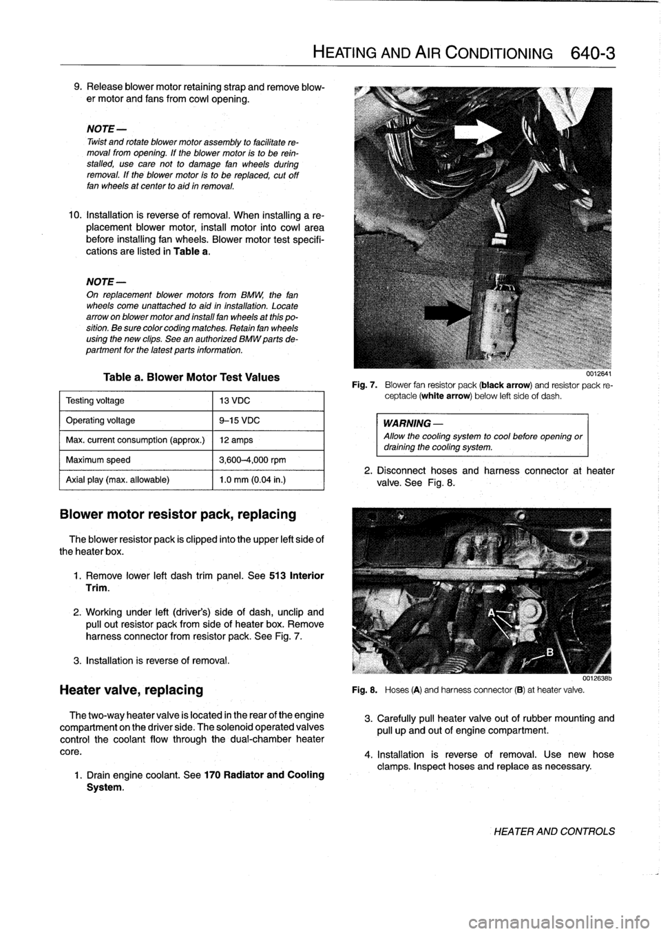
Blower
motor
resistor
pack,
replacing
The
blower
resistor
pack
is
clipped
into
the
upper
left
side
of
theheater
box
.
1
.
Remove
lower
left
dash
trim
panel
.
See513
Interior
Trim
.
2
.
Working
under
left
(driver's)
side
of
dash,
unclip
and
pulí
out
resistor
pack
from
sideof
heater
box
.
Remove
harness
connector
from
resistor
pack
.
See
Fig
.
7
.
3
.
Installation
is
reverse
of
removal
.
Heater
valve,
replacing
The
two-way
heater
valve
is
located
in
the
rear
of
the
engine
compartment
on
the
driver
side
.
The
solenoid
operated
valves
control
the
coolant
flow
through
the
dual-chamber
heater
core
.
1
.
Drain
engine
coolant
.
See
170
Radiator
and
Cooling
System
.
HEATING
AND
AIR
CONDITIONING
640-
3
uuiGO4I
Fig
.
7
.
Blower
fan
resistor
pack
(black
arrow)
and
resistor
pack
re-
ceptacle
(white
arrow)
below
left
sideof
dash
.
WARNING
-
Allow
the
cooling
system
to
cool
before
opening
ordraining
the
cooling
system
.
2
.
Disconnect
hoses
and
harness
connector
at
heater
valve
.
See
Fig
.
8
.
001[ó38b
Fig
.
S
.
Hoses
(A)
and
harnessconnector
(B)
at
heatervalve
.
3
.
Carefully
pull
heater
valve
out
of
rubber
mounting
and
pull
up
and
out
of
engine
compartment
.
4
.
Installation
is
reverse
of
removal
.
Use
new
hose
clamps
.
Inspect
hoses
and
replace
asnecessary
.
HEATER
AND
CONTROLS