washer BMW 318i 1995 E36 Owner's Manual
[x] Cancel search | Manufacturer: BMW, Model Year: 1995, Model line: 318i, Model: BMW 318i 1995 E36Pages: 759
Page 108 of 759
117-
1
2
CAMSHAFT
TIMING
CHAIN
4
.
Mount
primary
timing
chain
sprocket
to
primary
chain
so
that
arrowon
sprocket
faces
up
.
Mount
sprocket
to
camshaftso
that
tapped
holes
in
camshaftare
on
left
side
of
elongated
holes
in
sprocket
.
See
Fig
.
31
.
NOTE-
On
engines
built
beginning
from
March
1995,
the
VANOS
intake
cam
sprocket
assembly
was
updated
to
ínclude
a
spring
plate
and
two
thrust
washers
.
See
Fig
.
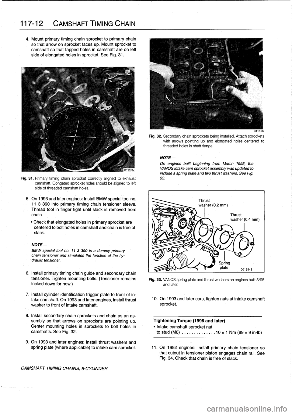
Fig
.
31
.
Primary
timing
chain
sprocket
correctly
alignedto
exhaust
33
.
camshaft
.
Elongated
sprocket
holes
should
be
aligned
to
left
side
of
threaded
camshaft
holes
.
5
.
On
1993
and
later
engines
:Install
BMW
special
tool
no
.
11-3
390
into
primary
timíng
chain
tensionersleeve
.
Thread
toolin
finger
tight
until
slack
is
removed
from
chain
.
"
Check
that
elongatedholes
in
primary
sprocket
are
centered
to
bolt
holes
in
camshaft
and
chain
is
free
of
slack
.
NOTE-
BMW
special
tool
no
.
11
3
390
ís
a
dummy
primary
chaín
tensioner
and
simulatesthe
function
of
the
hy-
draulic
tensíoner
.
7
.
Install
cylinder
identification
trigger
píate
to
front
of
in-
take
camshaft
.
On
1993
and
later
engines,
instanthrust
washer
tofrontof
intake
camshaft
.
CAMSHAFT
TIMING
CHAINS,
6-CYLINDER
B11136
Fig
.
32
.
Secondary
chain
sprockets
being
installed
.
Attach
sprockets
with
arrows
pointing
up
and
elongated
holes
centered
to
threaded
holes
in
shaft
flange
.
6
.
Install
primary
timing
chainguide
and
secondary
chain
tensioner
.
Tighten
mounting
bolts
.
(Tensioner
remains
Fig
.
33
.
VANOS
spring
plate
and
thrust
washers
on
engines
built
3/95locked
down
for
now
.)
and
later
.
10
.
On
1993
and
later
cars,
tighten
nuts
at
intake
camshaft
sprocket
.
8
.
Insta¡¡
secondary
chainsprockets
and
chain
asan
as-
sembly
so
that
arrows
on
sprockets
are
pointing
up
.
Tightening
Torque
(1996
and
later)
Centermounting
holes
in
sprockets
tobolt
holes
in
"
Intake
camshaft
sprocket
nut
camshafts
.
See
Fig
.
32
.
to
stud
(M6)
.............
.10t
1
Nm
(89
±9
in-lb)
9
.
On
1993
and
later
engines
:
Insta¡¡
thrust
washers
and
spring
plate
(where
applicable)
to
intake
cam
sprocket
.
11
.
On
1992
engines
:
Insta¡¡
primary
chain
tensioner
so
that
cutout
in
tensioner
piston
engages
chain
rail
.
See
Fig
.
34
.
Check
that
chain
is
free
of
slack
.
Page 109 of 759
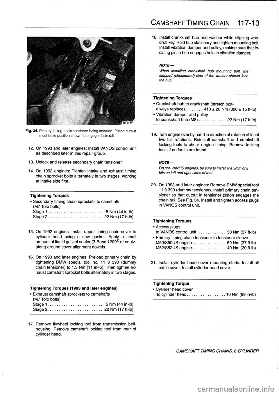
Fig
.
34
.
Primary
timíng
chain
tensioner
being
instafed
.
Pistoncutout
mustbe
in
position
shown
to
engage
chain
rail
.
12
.
On
1993
and
later
engines
:
Install
VANOS
control
unit
as
described
later
in
this
repair
group
.
13
.
Unlock
and
release
secondary
chaintensioner
.
NOTE-
On
pre-VANOS
engines,
be
sure
toinstall
the
3mm
drill
bits
on
left
and
right
sides
of
tool
.
14
.
On
1992
engines
:
Tighten
intake
and
exhaust
timing
chain
sprocket
bolts
alternately
in
two
stages,
working
at
intake
side
first
.
Tightening
Torques
"
Secondary
timing
chaira
sprockets
to
camshafts
(M7
Torx
bolts)
Stage
1
....
.
.
.
...
...............
5
Nm
(44
in-lb)
Stage
2
..
.
.
.
.
.
.
................
22
Nm
(17
ft-Ib)
15
.
On
1992
engines
:
Install
upper
timing
chaincover
to
cylinder
head
using
a
new
gasket
.
Apply
a
small
amount
ofliquid
gasket
sealer
(3-Bond
1209
®
orequiv-
alent)
around
coveralignment
dowels
.
16
.
On
1993
and
later
engines
:
Preloadprimary
chain
by
tightening
BMW
special
tool
no
.
11
3
390
(dummy
21
.
Install
cylinder
head
cover
mounting
studs
.
Insta¡¡
oil
chain
tensioner)
to
1
.3
Nm
(11
in-lb)
.
Then
tighten
ex-
baffle
cover
.
Install
cylinder
head
cover
.
haust
camshaft
sprocket
bolts
alternately
in
twostages
.
Tightening
Torques
(1993
and
later
engines)
"
Exhaust
camshaft
sprockets
to
camshafts
(M7
Torx
bolts)
Stage
1
..
...
..
..
................
5
Nm
(44
in-lb)
Stage
2
.....
.
.
...
..............
22
Nm
(17
ft-Ib)
17
.
Remove
flywheel
locking
tool
from
transmission
bell-
housing
.
Remove
camshaft
locking
tool
from
rear
of
cylinder
head
.
CAMSHAFT'TIMING
CHAIN
117-
1
3
18
.
Insta¡¡
crankshaft
hubandwasher
while
aligning
woo-
druff
key
.
Hold
hub
stationary
and
tighten
mounting
bolt
.
Install
vibration
damper
and
pulley,
making
sure
that
lo-
cating
pin
in
hub
engages
hole
in
vibration
damper
.
NOTE-
When
installing
crankshaft
hub
mounting
bolt,
the
stepped
(shouldered)
sideof
the
washer
should
fase
the
hub
.
Tightening
Torques
Crankshaft
hub
to
crankshaft
(stretch
bolt-
always
replace)
........
410
±
20
Nm
(300
±
15
ft-1b)
"
Vibration
damper
and
pulley
to
crankshaft
hub
(M8)
...
..
.
..
....
22
Nm
(17
ft-Ib)
19
.
Turn
engine
over
by
hand
in
direction
of
rotation
atleast
two
full
rotations
.
Reinstall
camshaft
and
crankshaft
locking
tools
to
check
engine
timing
.
Remove
locking
tools
if
no
faults
are
found
.
20
.
On
1993
and
later
engines
:
Remove
BMW
special
tool11
3
390
(dummy
tensioner)
.
Install
primary
chain
ten-sioner
so
that
cutout
in
tensioner
piston
engages
the
chain
rail
.
See
Fig
.
34
.
Install
and
tighten
access
plugs
in
VANOS
control
unit
.
Tightening
Torques
"
Access
plugs
to
VANOS
control
unit
..........
.
..
50
Nm
(37
ft-Ib)
"
Primary
timing
chain
tensioner
to
tensioner
sleeve
M50/S50US
engine
.......
.
..
..
.
.
50
Nm
(37
ft-Ib)
M52/S52US
engine
..........
..
.
.
40
Nm
(30
ft-Ib)
Tightening
Torque
"
Cylinder
head
cover
to
cylinder
head
............
...
.
.10
Nm
(89
in-lb)
CAMSHAFT
TIMINGCHAINS,
6-CYLINDER
Page 160 of 759
130-
1
4
FUEL
INJECTION
NOTE-
Be
sure
to
retrieve
thrust
washer
behind
fuel
pressure
regulator
on
6-cylinder
engine
.
4
.
Installation
is
reverse
of
removal
.
Replace
O-rings
.
Fuel
pressure
regulator,
replacing
(under
car
mount)
WARNING
-
Fuel
will
be
discharged
.
Do
not
disconnect
any
wires
that
could
cause
electrical
sparks
.
Do
not
smoke
or
work
near
heaters
or
other
fire
hazards
.
Keep
an
approved
tire
extinguisher
handy
.
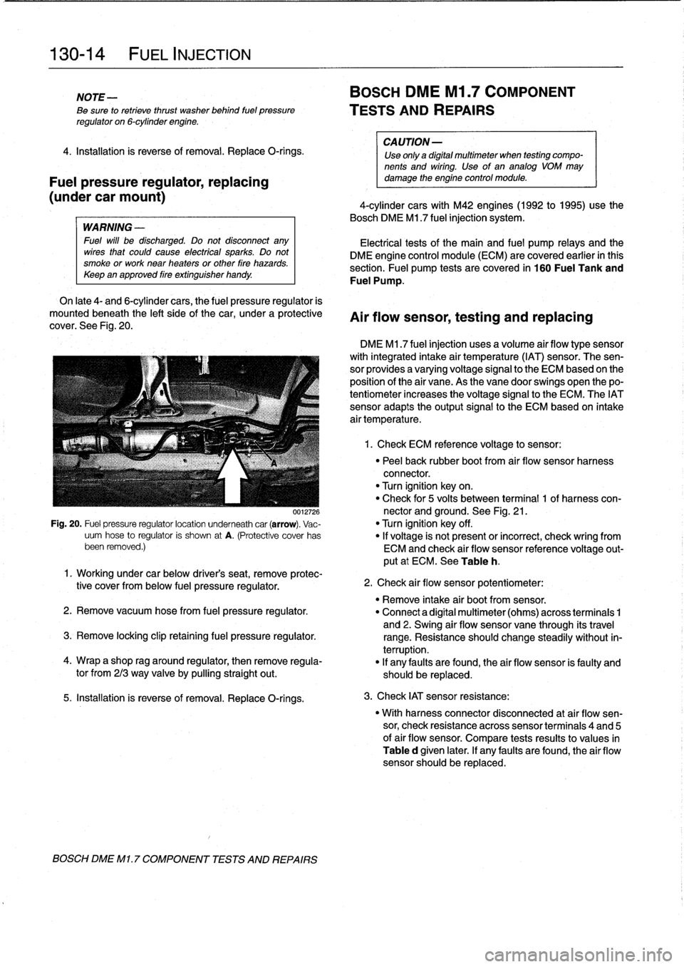
On
late
4-
and
6-cylinder
cars,
the
fuel
pressure
regulator
is
mounted
beneath
the
left
sideof
the
car,
under
a
protective
cover
.
See
Fig
.
20
.
0012726
Fig
.
20
.
Fuel
pressure
regulatorlocation
underneath
car
(arrow)
.
Vac-
uum
hose
to
regulator
is
shown
at
A
.
(Protective
cover
has
been
removed
.)
5
.
Installation
is
reverse
of
removal
.
Replace
O-rings
.
BOSCH
DME
Ml
.
7
COMPONENT
TESTS
AND
REPAIRS
BOSCH
DME
Ml
.7
COMPONENT
TESTS
AND
REPAIRS
CA
UTION-
Use
only
a
digital
multimeter
when
testing
compo-
nents
and
wiring
.
Use
of
an
analog
VOM
may
damage
the
engine
control
module
.
4-cylinder
cars
with
M42
engines(1992
to
1995)use
the
Bosch
DME
M1
.7
fuel
injection
system
.
Electrical
tests
of
the
main
and
fuel
pump
relays
and
the
DME
engine
control
module
(ECM)
are
covered
earlier
in
this
section
.
Fuel
pump
tests
arecovered
in
160
Fuel
Tank
and
Fuel
Pump
.
Air
flow
sensor,
testing
and
replacing
DME
M1
.7
fuel
injection
uses
a
volume
air
flow
type
sensor
with
integrated
intake
air
temperature
(IAT)
sensor
.
The
sen-
sor
provides
a
varyingvoltage
signal
to
the
ECM
based
on
the
position
of
the
air
vane
.
As
the
vane
doorswings
open
thepo-
tentiometer
increases
the
voltage
signal
to
the
ECM
.
The
IATsensor
adapts
theoutput
signal
to
the
ECM
based
on
intake
air
temperature
.
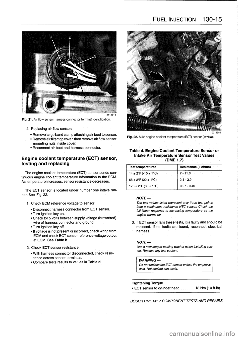
1
.
Check
ECM
reference
voltage
to
sensor
:
"
Peel
back
rubber
boot
from
air
flow
sensor
harness
connector
.
"
Turn
ignition
keyon
.
"
Check
for
5
volts
between
terminal
1
of
harness
con-
nector
and
ground
.
See
Fig
.
21
.
"
Turn
ignition
key
off
.
"
If
voltage
is
not
present
or
incorrect,
check
wring
from
ECM
and
check
air
flow
sensor
reference
voltage
out-
put
at
ECM
.
See
Table
h
.
1
.
Working
under
car
below
driver's
seat,
remove
protec-
tive
cover
from
below
fuel
pressure
regulator
.
"
Remove
intake
air
bootfrom
sensor
.
2
.
Remove
vacuum
hosefrom
fuel
pressure
regulator
.
"
Connect
a
digital
multimeter
(ohms)
across
terminais
1
and
2
.
Swing
air
flow
sensor
vane
through
its
travel
3
.
Remove
locking
clip
retaining
fuel
pressure
regulator
.
range
.
Resistance
should
change
steadily
without
in-
terruption
.
4
.
Wrap
a
shop
rag
around
regulator,
then
remove
regula-
"
If
any
faults
are
found,
the
air
flow
sensor
is
faulty
and
tor
from
213
way
valve
by
pullingstraight
out
.
should
be
replaced
.
2
.
Check
air
flow
sensor
potentiometer
:
3
.
Check
IAT
sensor
resistance
:
"
With
harness
connector
disconnected
at
air
flow
sen-
sor,
check
resistance
across
sensor
terminais
4
and
5
of
air
flow
sensor
.
Compare
tests
results
to
values
in
Table
d
given
later
.
If
any
faults
are
found,
the
air
flow
sensor
should
be
replaced
.
Page 161 of 759
u0
I
.[
Ia
Fig
.
21
.
Air
flow
sensor
harness
connector
terminal
identification
.
4
.
Replacing
air
flow
sensor
:
"
Remove
large
band
clamp
attaching
air
boot
to
sensor
.
"
Remove
airfiltertop
cover,
then
remove
airflow
sensor
mounting
nuts
inside
cover
.
"
Reconnect
air
boot
and
harness
connector
.
Engine
coolant
temperature
(ECT)
sensor,
testing
and
replacing
The
engine
coolant
temperature
(ECT)
sensor
sends
con-
tinuous
engine
coolant
temperature
information
to
the
ECM
.
As
temperature
increases,
sensor
resistance
decreases
.
"
With
harness
connector
disconnected,
check
resis-
tance
across
sensor
terminals
.
"
Compare
tests
results
to
values
in
Table
d
.
FUEL
INJECTION
130-
1
5
0011984
Fig
.
22
.
M42
engine
coolant
temperature
(ECG
sensor
(arrow)
.
Table
d
.
Engine
Coolant
Temperature
Sensoror
Intake
Air
TemperatureSensor
Test
Values
(DME
1
.7)
Test
temperatures
Resistance
(k
ohms)
',
14±2°F(-10t1°C)
7-11
.6
68±2°F
(20
t
1
°C)
2
.1
-2
.9
176
±
2°F
(80
t
V
C)
0
.27-0
.40
The
ECT
sensor
is
located
under
number
one
intake
run-
'
ner
.
See
Fig
.
22
.
NOTE-
1
.
Check
ECM
referente
voltage
to
sensor
:
The
test
values
listed
represent
only
three
test
points
from
a
continuous
resistance
NTC
sensor
.
Check
the
"
Disconnect
harness
connectorfrom
ECT
sensor
.
full
linear
response
to
increasing
temperature
as
the
"
Turn
ignition
key
on
.
engine
warms
up
.
"
Check
for
5
volts
between
supply
voltage
(brown/red)
wire
of
harness
connector
and
ground
.
3
.
If
ECT
sensor
fails
these
tests,
it
is
faulty
and
should
be
"
Turn
ignition
key
off
.
replaced
.
If
no
faults
are
found,
reconnect
electrical
"
If
voltage
is
not
present
or
incorrect,
check
wring
from
harness
.
ECM
and
check
ECT
sensor
reference
voltage
output
at
ECM
.
See
Table
h
.
NOTE-
2
.
Check
ECT
sensor
resistance
:
Use
a
new
copper
sealing
washer
when
installing
sen-
sor
.
Reptace
any
lost
coolant
.
WARNING
-
Do
not
replace
the
ECT
sensor
unlessthe
engine
is
cold
.
Hot
coolant
can
scald
.
Tightening
Torque
"
ECT
sensor
to
cylinder
head
.....
..
13
Nm
(10
ft-Ib)
BOSCH
DME
M1
.7
COMPONENT
TESTS
AND
REPAIRS
Page 165 of 759
Table
f
.
Engine
Coolant
TemperatureSensor
or
Intake
Air
TemperatureSensor
Test
Values
(DME
3
.113
.3
.1)
Test
temperatures
Resistance
(k
ohms)
14±
2°F
(-10
±
1'C)
7-11
.6
68±
2°F
(20
±
1'C)
2
.1
-2
.9
17612°F
(80
t
V
C)
0
.27-0
.40
NOTE
The
test
values
listed
represent
only
three
test
points
from
a
continuous
resistance
NTC
sensor
.
Check
the
full
linear
response
to
increasing
temperatures
as
the
engine
warms
up
.
3
.
If
ECT
sensor
fails
these
tests,
it
is
faulty
and
should
be
replaced
.
If
no
faults
are
found,
reconnect
electrical
harness
.
WARNING
-
Do
not
replace
the
ECT
sensor
unless
the
engine
is
cold
.
Hot
coolant
can
scald
.
NOTE-
Use
"
a
new
copper
sealing
washer
when
installing
sensor
.
Replace
any
lost
coolant
.
Tightening
Torque
"
Engine
coolant
temperature
sensor
to
cylinder
head
.........
..
.
..
...
13
Nm
(10
ft-lb)
Intake
air
temperature
(IAT)
sensor,
testing
and
replacing
The
intake
air
temperature
(IAT)
sensor
signal
is
usedasa
correction
factor
for
fuel
injection
and
ignition
timing
.
Thissen-
sor
is
mounted
in
the
intake
manifold
behind
the
throttle
posi-
tion
switch
.
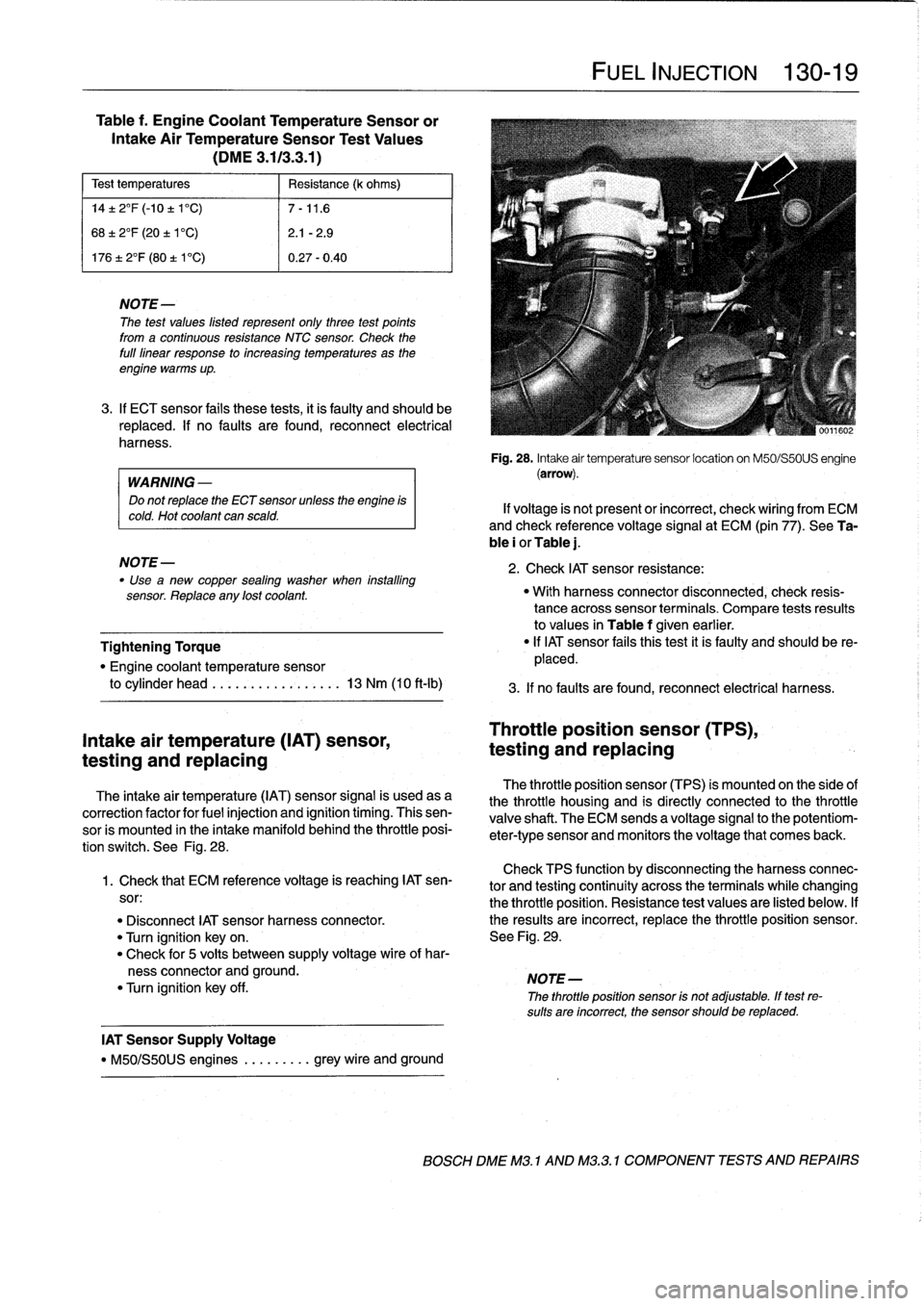
See
Fig
.
28
.
Check
TPS
function
by
disconnecting
theharnessconnec-
1
.
Check
that
ECM
reference
voltage
is
reaching
IAT
sen-
tor
and
testing
continuity
across
the
terminalswhile
changing
sor
:
the
throttle
position
.
Resistance
test
values
are
listed
below
.
If
"
Disconnect
IAT
sensor
harness
connector
.
the
resuits
are
incorrect,
replace
the
throttle
position
sensor
.
"
Turn
ignition
keyon
.
See
Fig
.
29
.
"
Check
for
5
volts
between
supply
voltage
wire
of
har-
ness
connector
and
ground
.
NOTE-
"
Turn
ignition
key
off
.
The
throttle
position
sensor
is
not
adjustable
.
If
test
re-
sults
are
incorrect,
the
sensor
should
be
replaced
.
IAT
Sensor
Supply
Voltage
"
M50/S50US
engines
.
........
grey
wire
and
ground
FUEL
INJECTION
130-19
Fig
.
28
.
Intake
air
temperature
sensor
location
on
M50/S50US
engine
(arrow)
.
If
voltage
is
not
present
or
incorrect,
check
wiring
from
ECM
and
check
reference
voltage
signal
at
ECM
(pin
77)
.
See
Ta-
ble
i
or
Table
j
.
2
.
Check
IAT
sensor
resistance
:
"
With
harness
connector
disconnected,
check
resis-
tance
acrosssensor
terminals
.
Compare
tests
resuits
to
values
in
Table
f
given
earlier
.
"
If
IAT
sensor
fafs
thistest
it
is
faulty
and
should
be
re-
placed
.
3
.
If
no
faults
are
found,
reconnect
electrical
harness
.
Throttle
position
sensor
(TPS),
testing
and
replacing
The
throttle
position
sensor
(TPS)
is
mounted
on
the
side
of
the
throttle
housing
and
is
directly
connected
to
the
throttle
valve
shaft
.
The
ECM
sends
a
voltage
signal
to
the
potentiom-
eter-type
sensor
and
monitors
the
voltage
that
comes
back
.
BOSCH
DME
M3
.
1
AND
M32
.1
COMPONENT
TESTS
AND
REPAIRS
Page 168 of 759
130-
2
2
FUEL
INJECTION
Mass
air
flow
sensor,
replacing
1
.
Disconnect
harness
connector
and
intake
air
bootfrom
air
flow
sensor
.
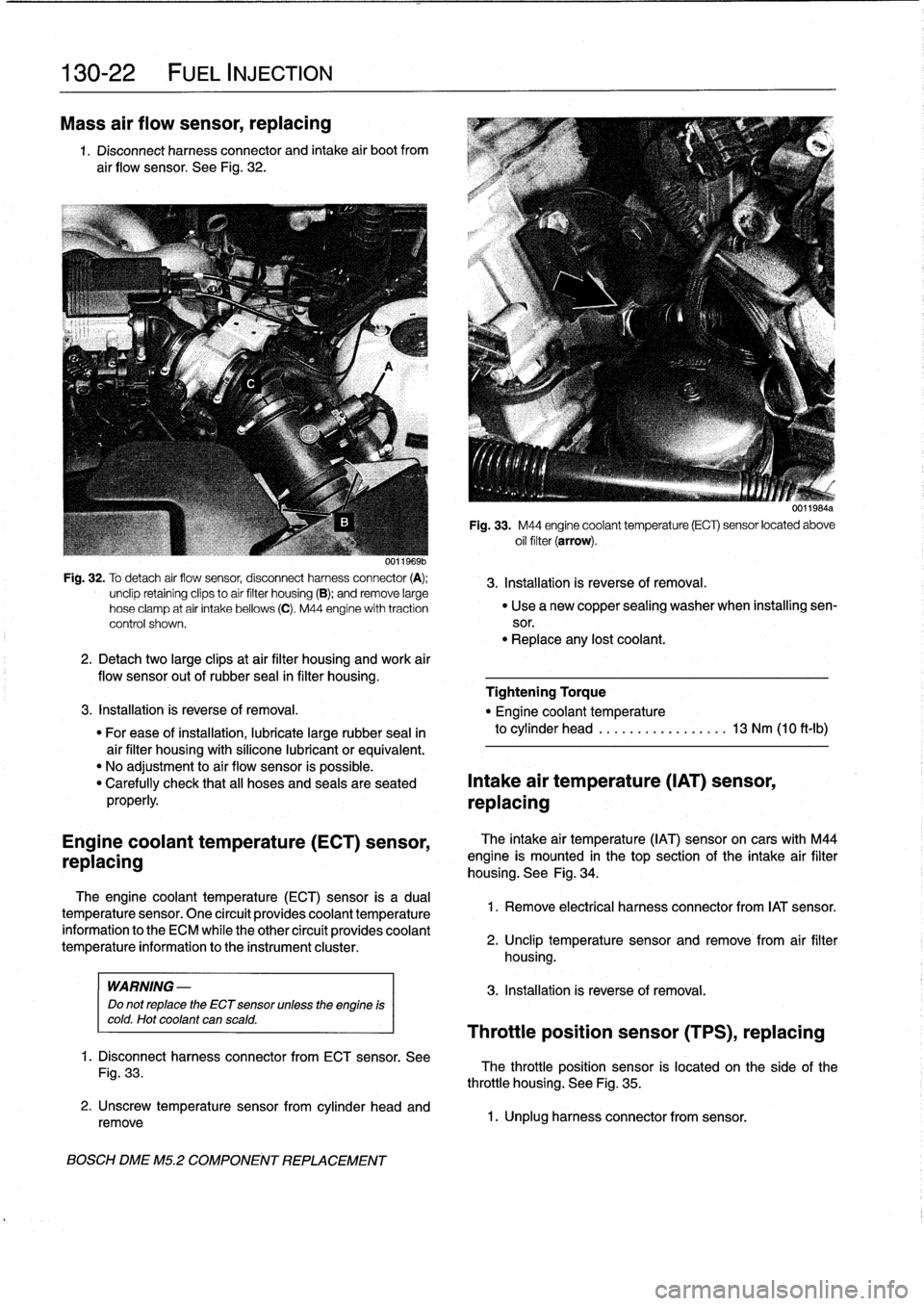
See
Fig
.
32
.
Fig
.
32
.
To
detach
air
flow
sensor,
disconnect
harness
connector
(A)
;
3
.
Installation
is
reverse
of
removal
.
unclip
retainíng
clips
to
aír
filter
housing
(B)
;
andremove
large
hose
clamp
at
air
intake
bellows
(C)
.
M44
engine
with
traction
"
Use
a
new
copper
sealing
washer
when
installing
sen-
control
shown
.
sor
.
"
Replace
any
lost
coolant
.
2
.
Detachtwo
large
clipsat
air
filter
housing
and
work
air
flow
sensor
out
of
rubber
seal
in
filter
housing
.
Tightening
Torque
3
.
Installation
is
reverse
of
removal
.
"
Engine
coolant
temperature
"
For
ease
of
installation,
lubricate
large
rubber
seal
in
to
cylinder
head
.............
.
..
.
13
Nm
(10
ft-Ib)
air
filter
housing
with
silicone
lubricant
or
equivalent
.
"
No
adjustment
to
air
flow
sensor
is
possible
.
"
Carefully
check
that
all
hoses
and
seals
are
seated
Intake
air
temperature
(IAT)
sensor,
properly
.
replacing
Engine
coolant
temperature
(ECT)
sensor,
replacing
The
engine
coolant
temperature
(ECT)sensor
is
a
dual
temperature
sensor
.
One
circuít
provides
coolant
temperature
information
to
the
ECM
while
the
other
circuít
provides
coolant
temperature
information
to
the
instrument
cluster
.
WARNING
-
Do
not
replace
the
ECT
sensor
unless
the
engine
is
cold
.
Hot
coolant
can
scald
.
1
.
Disconnect
harness
connector
from
ECT
sensor
.
See
Fig
.
33
.
2
.
Unscrew
temperature
sensorfrom
cylinder
head
and
remove
BOSCH
DME
M5
.2
COMPONENT
REPLACEMENT
U1111
bis4a
Fig
.
33
.
M44
engine
coolant
temperature
(ECT)
sensor
located
above
oil
filter
(arrow)
.
The
intake
air
temperature
(IAT)
sensoron
cars
with
M44
engine
is
mounted
in
thetop
section
of
the
intake
air
filter
housing
.
See
Fig
.
34
.
1
.
Remove
electrical
harness
connector
from
IAT
sensor
.
2
.
Unclip
temperature
sensor
and
remove
from
air
filter
housing
.
3
.
Installation
is
reverse
of
removal
.
Throttle
position
sensor
(TPS),
replacing
The
throttle
position
sensor
is
located
on
the
side
of
the
throttle
housing
.
See
Fig
.
35
.
1
.
Unplug
harness
connector
from
sensor
.
Page 171 of 759
Mass
air
flow
sensor,
replacing
1
.
Disconnect
harness
connector
and
intake
air
boots
from
air
flow
sensor
.
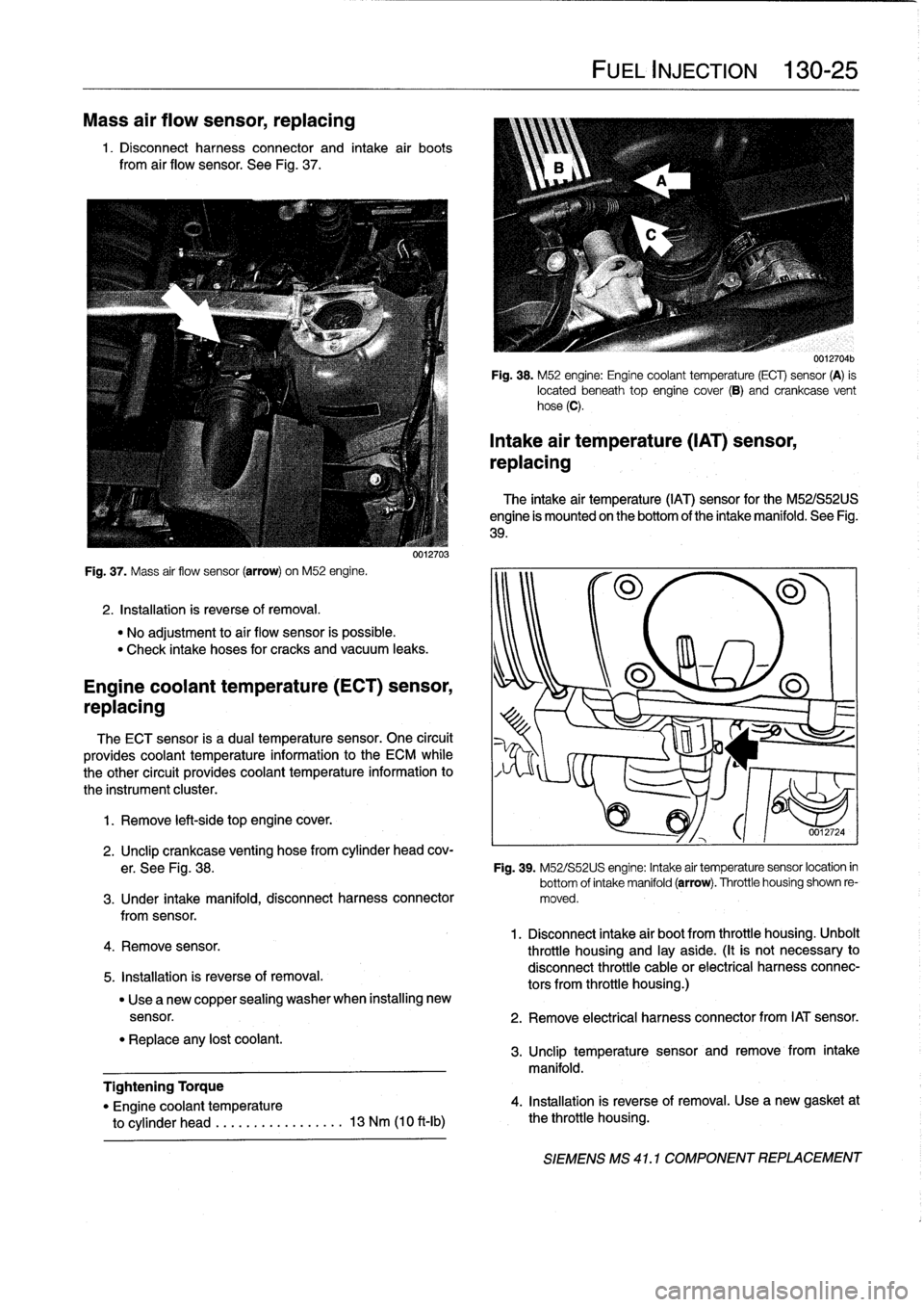
See
Fig
.
37
.
Fig
.
37
.
Mass
air
flow
sensor
(arrow)
on
M52
engine
.
2
.
Installation
is
reverse
of
removal
.
"
No
adjustment
to
aír
flow
sensor
is
possible
.
"
Check
intake
hoses
for
cracks
and
vacuum
leaks
.
Engine
coolant
temperature(ECT)
sensor,
replacing
The
ECT
sensor
is
a
dual
temperature
sensor
.
One
circuit
provides
coolant
temperature
information
to
the
ECM
while
the
other
circuit
provides
coolant
temperature
information
to
the
instrument
cluster
.
1
.
Remove
left-side
top
engine
cover
.
4
.
Remove
sensor
.
5
.
Installation
is
reverse
of
removal
.
"
Replace
any
lost
coolant
.
0012703
"
Use
a
new
copper
sealing
washer
when
installing
new
Tightening
Torque
"
Engine
coolant
temperature
to
cylinder
head
.....
..
.
...
......
13
Nm
(10
ft-Ib)
FUEL
INJECTION
130-
25
0012704b
Fig
.
38
.
M52
engine
:
Engine
coolant
temperature
(ECT)
sensor
(A)
is
located
beneath
top
engine
cover
(8)
and
crankcase
vent
hose
(C)
.
Intake
air
temperature
(IAT)
sensor,
replacing
The
intake
air
temperature
(IAT)
sensor
for
the
M52/S52US
engine
is
mounted
on
the
bottom
of
the
intake
manifold
.
See
Fig
.
39
.
2
.
Unclip
crankcase
venting
hose
from
cylinder
head
cov-
er
.
See
Fig
.
38
.
Fig
.
39
.
M52/S52US
engine
:
Intake
air
temperaturesensor
location
in
bottom
of
intake
manifold(arrow)
.
Throttle
housing
shown
re
3
.
Under
intake
manifold,
disconnect
harness
connector
moved
.
fromsensor
.
1
.
Disconnect
intake
air
bootfrom
throttle
housing
.
Unbolt
throttle
housing
and
¡ay
aside
.
(It
is
not
necessary
to
disconnect
throttle
cable
or
electrical
harnessconnec-
tors
from
throttle
housing
.)
sensor
.
2
.
Remove
electrical
harness
connector
from
IAT
sensor
.
3
.
Unclip
temperature
sensor
and
remove
from
intake
manifold
.
4
.
Installation
is
reverse
of
removal
.
Use
a
new
gasket
at
the
throttle
housing
.
SIEMENS
MS
41
.1
COMPONENT
REPLACEMENT
Page 200 of 759
170-6
RADIATOR
AND
COOLING
SYSTEM
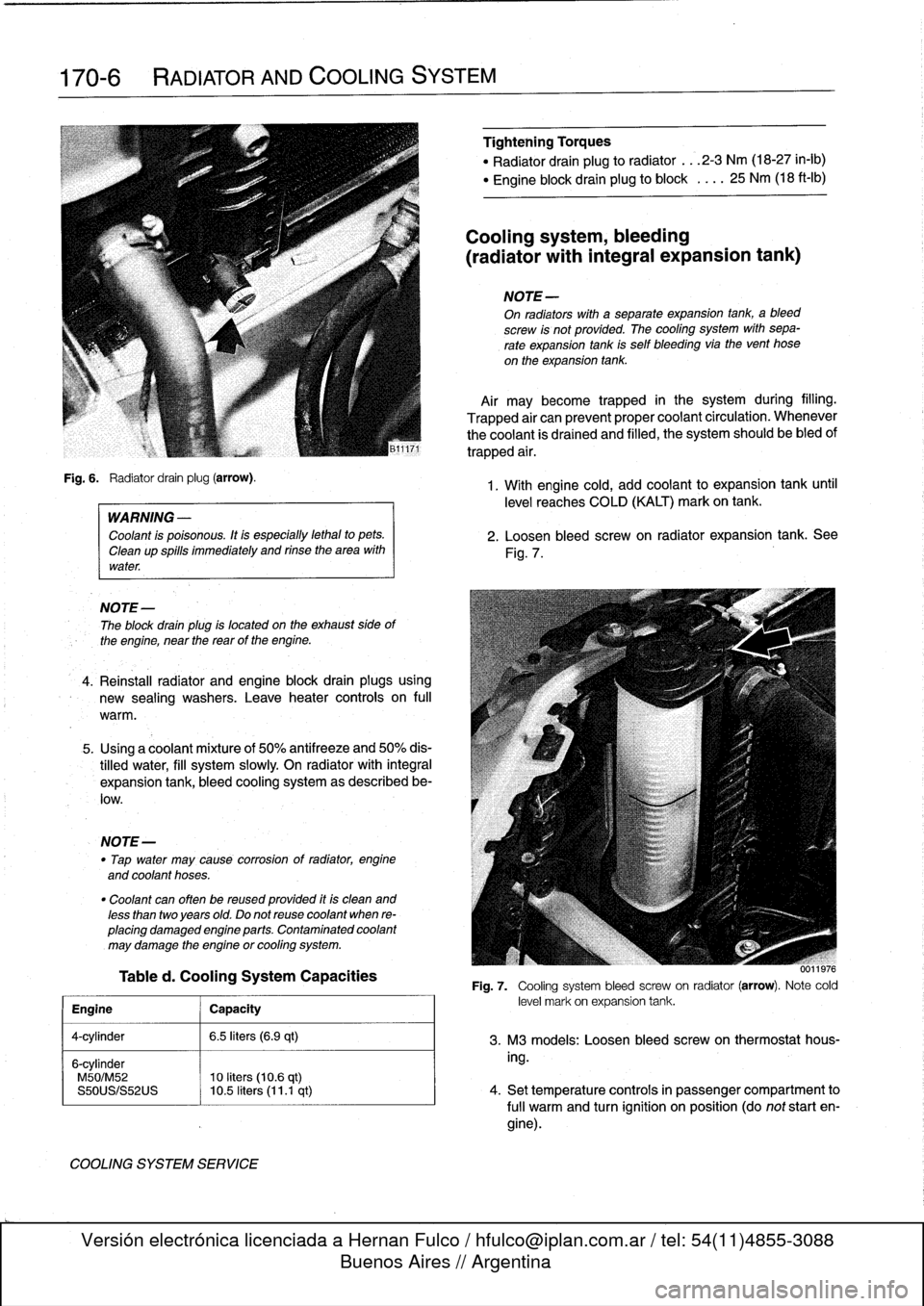
Fig
.
6
.
Radiator
drain
plug
(arrow)
.
WARNING
-
Coolant
is
poisonous
.
Itis
especially
lethal
to
pets
.
Cleanup
spills
immediately
and
rinse
the
area
with
water
.
NOTE
-
The
block
drain
plug
is
located
on
the
exhaust
side
of
the
engine,
near
the
reas
of
the
engine
.
4
.
Reinstall
radiator
and
engine
block
drain
plugsusing
new
sealing
washers
.
Leave
heater
controis
on
full
warm
.
5
.
Using
a
coolantmixture
of
50%
antifreeze
and
50%
dis-
tilled
water,
fill
system
slowly
On
radiator
with
integral
expansion
tank,
bleed
cooling
system
as
described
be-
low
.
NOTE-
"
Tap
water
may
cause
corrosion
of
radiator,
engine
and
coolant
hoses
.
"
Coolant
can
often
be
reused
provided
itis
clean
and
less
than
twoyears
old
.
Do
not
reuse
coolant
when
re-
placing
damaged
engine
parts
.
Contaminated
coolant
may
damage
the
engine
or
cooling
system
.
Tabled
.
Cooling
System
Capacities
Engine
j
Capacity
4-cylinder
1
6
.5
liters
(6.9
qt)
6-cylinder
M50/M52
10
liters
(10
.6
qt)
S50US/S52US
10
.5
liters
(11
.1
qt)
COOLING
SYSTEM
SERVICE
Tightehing
Torques
"
Radiator
drain
plug
to
radiator
...
2-3
Nm
(18-27
in-lb)
"
Engine
block
drain
plug
to
block
.
.
..
25
Nm
(18
ft-Ib)
Cooling
system,
bleeding
(radiator
with
integral
expansion
tank)
NOTE
-
On
radiators
with
a
separate
expansion
tank,
ableed
screw
is
not
provided
.
The
cooling
system
with
sepa-
rate
expansion
tank
is
self
bleeding
via
the
vent
hose
on
the
expansion
tank
.
Air
maybecome
trapped
in
the
system
during
filling
.
Trapped
air
can
prevent
proper
coolant
circulation
.
Whenever
the
coolant
is
drained
and
filled,
the
system
should
be
bled
of
trapped
air
.
1
.
With
engine
cold,
add
coolant
to
expansion
tank
until
level
reaches
COLD
(KALT)
mark
on
tank
.
2
.
Loosen
bleed
screw
on
radiator
expansion
tank
.
See
Fig
.
7
.
0011976
Fig
.
7
.
Cooling
system
bleed
screwon
radiator
(arrow)
.
Note
cold
level
mark
on
expansion
tank
.
3
.
M3
models
:
Loosen
bleed
screw
on
thermostathous-
ing
.
4
.
Set
temperature
controls
in
passenger
compartment
to
fui¡
warm
and
turn
ignition
on
position
(do
not
start
en-
gine)
.
Page 226 of 759
230-
6
MANUAL
TRANSMISSION
Transmission,
removing
and
installing
1
.
Disconnect
negative
(-)
cable
from
battery
.
CAUTION-
Prior
to
disconnecting
the
battery,
read
the
battery
disconnection
cautions
given
at
the
front
of
this
manual
onpage
viii
.
2
.
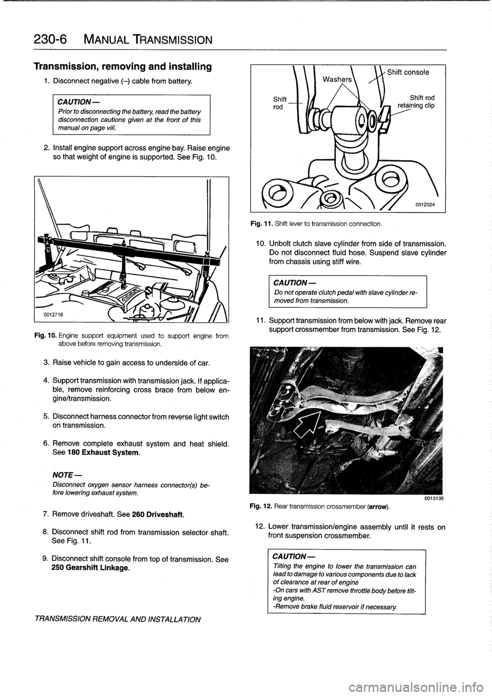
Insta¡¡
enginesupportacrossengine
bay
.
Raise
engine
so
that
weight
of
engine
ís
supported
.
See
Fig
.
10
.
Fig
.
10
.
Engine
support
equipment
used
to
support
engine
from
above
before
removing
transmission
.
3
.
Raise
vehicle
to
gain
access
to
underside
of
car
.
4
.
Support
transmission
with
transmission
jack
.
lf
applica-
ble,
remove
reinforcing
cross
brace
from
belowen-
gine/transmission
.
5
.
Disconnect
harnesscon
nector
from
reverse
light
switch
on
transmission
.
6
.
Remove
completeexhaustsystem
and
heat
shield
.
See
180
Exhaust
System
.
NOTE-
Disconnect
oxygensensor
hamess
connector(s)be-
fore
lowering
exhaust
system
.
7
.
Remove
driveshaft
.
See260
Driveshaft
.
8
.
Disconnect
shift
rod
from
transmission
selectorshaft
.
See
Fig
.
11
.
9
.
Disconnect
shift
console
fromtop
of
transmission
.
See
250
Gearshift
Linkage
.
TRANSMISSION
REMOVAL
AND
INSTALLATION
Washers
Shift
Shift
rod
rod
retaining
clip
0
0
,
Fig
.
11
.
Shift
lever
to
transmission
connection
.
Shift
console
0012024
10
.
Unbolt
clutch
slave
cylinder
from
sideof
transmission
.
Do
not
disconnect
fluid
hose
.
Suspend
slavecylinder
from
chassis
using
stiff
wire
.
CAUTION-
Do
not
operate
clutch
pedal
with
slave
cylinder
re-
moved
from
transmission
.
11
.
Support
transmission
from
below
with
jack
.
Remove
rear
support
crossmember
from
transmission
.
See
Fig
.
12
.
Fig
.
12
.
Rear
transmission
crossmember
(arrow)
.
12
.
Lower
transmission/engine
assembly
until
it
rests
on
front
suspension
crossmember
.
CAUTION-
Tilting
the
engine
to
lower
thetransmission
can
lead
to
damage
to
various
componente
due
to
lackof
clearance
at
rear
of
engine
-On
cars
with
AST
remove
throttle
body
before
tilt-
ing
engine
.
-Remove
brace
fluid
reservoir
if
necessary
.
0013135
Page 227 of 759
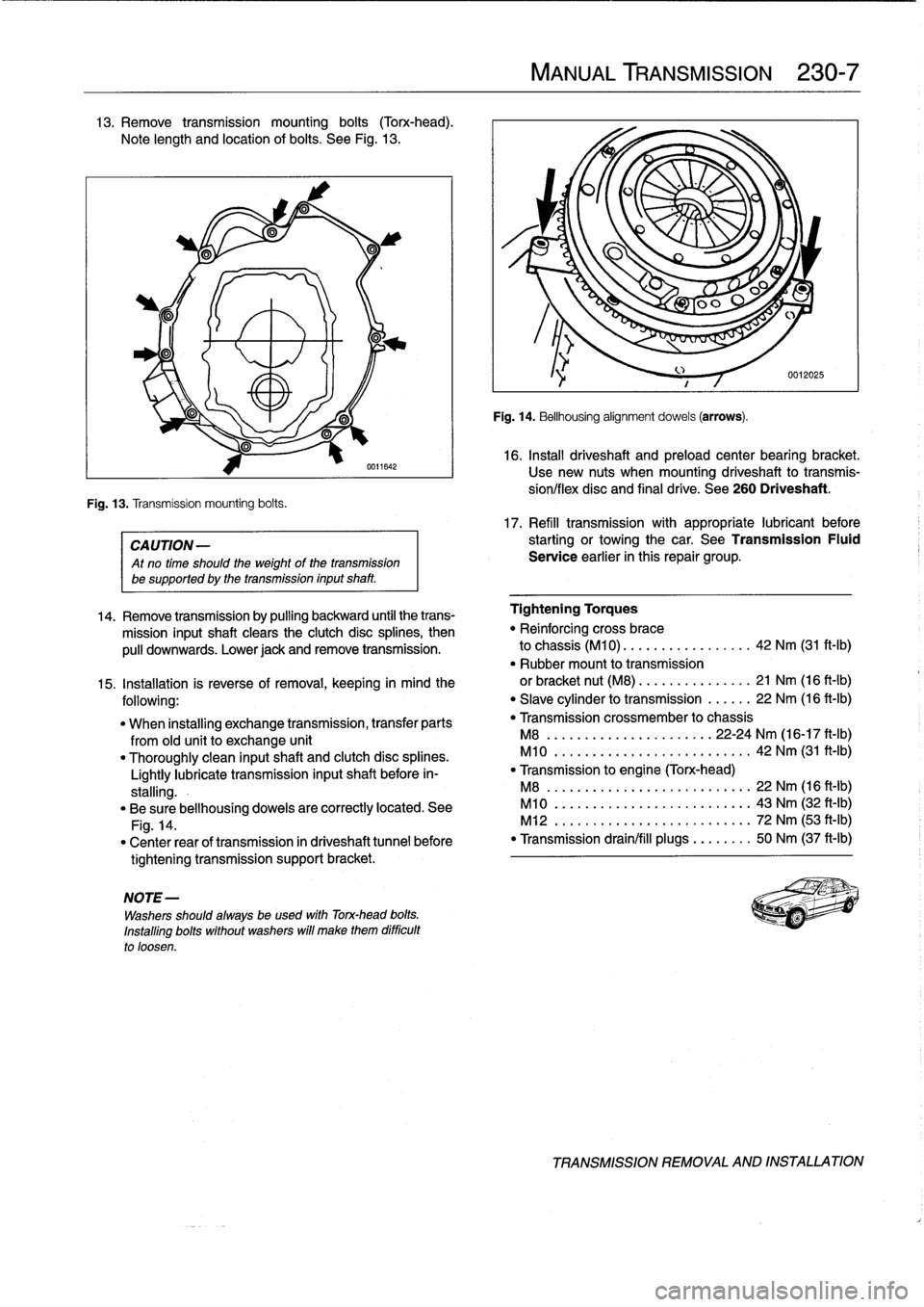
13
.
Remove
transmission
mounting
bolts
(Torx-head)
.
Note
length
and
location
of
bolts
.
See
Fig
.
13
.
Fig
.
13
.
Transmission
mounting
bolts
.
0611642
CA
UTION-
Atno
time
should
the
weight
of
thetransmission
be
supported
by
the
transmission
inputshaft
.
NOTE
-
Washers
should
always
be
used
with
Torx-head
bolts
.
Installing
bolts
without
washers
will
make
them
difficult
to
loosen
.
MANUAL
TRANSMISSION
230-
7
Fig
.
14
.
Bellhousing
alignment
dowels
(arrows)
.
16
.
Install
driveshaft
and
preload
center
bearing
bracket
.
Usenew
nuts
when
mounting
driveshaft
to
transmis-
síon/flex
disc
and
final
drive
.
See
260
Driveshaft
.
17
.
Refill
transmission
with
appropriate
lubricant
before
starting
or
towingthe
car
.
See
Transmission
Fluid
Service
earlier
in
this
repair
group
.
14
.
Remove
transmission
by
pulling
backward
until
the
trans-
Tightening
Torques
mission
inputshaft
clears
the
clutch
disc
splines,
then
"
Reinforcing
cross
brace
pulí
downwards
.
Lower
jack
andremove
transmission
.
to
chassis
(M10)
.
...
.............
42
Nm
(31
ft-Ib)
"
Rubber
mount
to
transmission
15
.
Installation
is
reverse
of
removal,
keeping
in
mind
the
or
bracket
nut
(M8)
.
...
.
...
.......
21
Nm
(16
ft-Ib)
following
:
"
Slave
cylinder
to
transmission
......
22
Nm
(16
ft-Ib)
"
When
installing
exchange
transmission,
transfer
parts
"
Transmission
crossmember
to
chassis
from
old
unit
to
exchange
unit
M8
...............
.
.
...
..
22-24
Nm
(16-17
ft-Ib)
"
Thoroughly
clean
inputshaft
and
clutch
disc
splines
.
M10
..............
.
..
..
.......
42
Nm
(31
ft-Ib)
Lightly
lubrícate
transmission
inputshaft
before
in-
"
Transmission
to
engine
(Torx-head)
stalling
.-
M8
..
..................
..
.
..
..
22
Nm
(16
ft-Ib)
"
Be
sure
bellhousing
dowels
are
correctly
located
.
See
M10
.
.................
...
.
..
..
43
Nm
(32
ft-Ib)
Fig
.
14
.
M12
.
..................
..
.
..
..
72
Nm
(53
ft-Ib)
"
Center
rear
of
transmission
in
driveshaft
tunnel
before
"
Transmission
drain/fill
plugs
.
..
.
..
..
50
Nm
(37
ft-Ib)
tightening
transmission
support
bracket
.
TRANSMISSION
REMOVAL
AND
INSTALLATION