switch BMW 318i 1997 E36 Workshop Manual
[x] Cancel search | Manufacturer: BMW, Model Year: 1997, Model line: 318i, Model: BMW 318i 1997 E36Pages: 759
Page 434 of 759
612-6
SWITCHES
AND
ELECTRICAL
ACCESSORIES
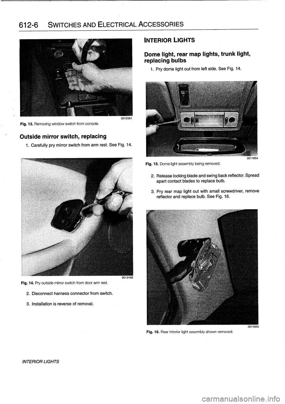
Fig
.
13
.
Removing
window
switch
from
console
.
Outside
mirror
switch,
replacing
0012561
1
.
Carefully
pry
mirror
switch
from
arm
rest
.
See
Fig
.
14
.
Fig
.
14
.
Pry
outside
mirror
switch
from
door
arm
rest
.
2
.
Disconnectharness
connector
from
switch
.
3
.
Installation
is
reverseof
removal
.
INTERIOR
LIGHTS
0013168
INTERIOR
LIGHTS
Dome
light,
rear
map
lights,
trunk
light,
replacing
bulbs
1
.
Pry
dome
light
out
from
left
side
.
See
Fig
.
14
.
Fig
.
15
.
Dome
light
assembly
being
removed
.
2
.
Release
locking
blade
and
swing
back
reflector
.
Spread
apart
contact
blades
toreplace
buib
.
3
.
Pry
rear
map
light
out
with
small
screwdriver,
remove
reflector
and
replace
bulb
.
See
Fig
.
16
.
Fig
.
16
.
Rear
interior
light
assembly
shown
removed
.
0011855
Page 435 of 759
4
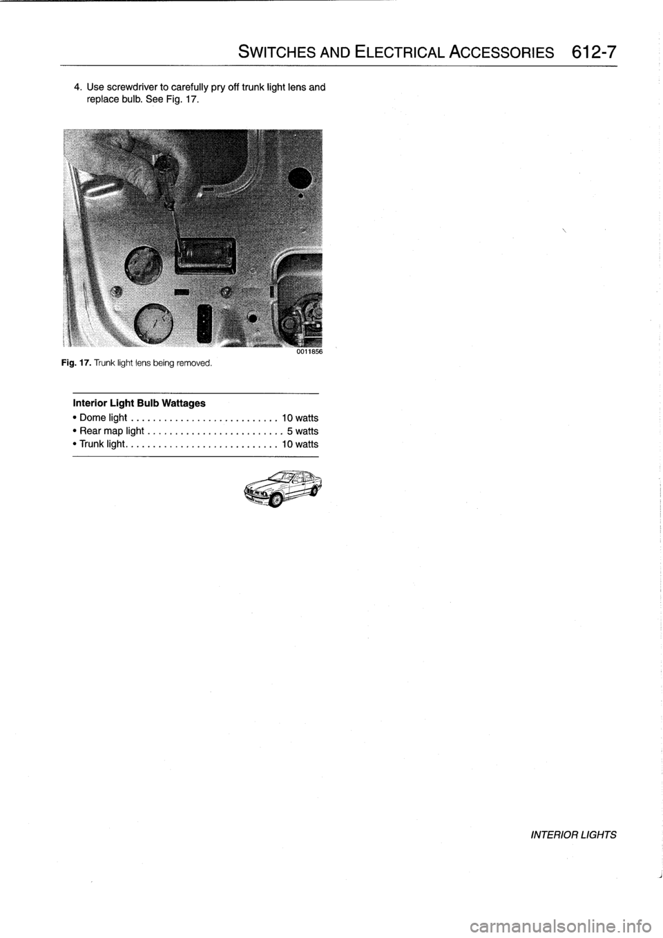
.
Use
screwdriver
to
carefully
pry
off
trunk
light
lens
and
replace
bulb
.
See
Fig
.
17
.
Fig
.
17
.
Trunk
light
lens
being
removed
.
Interior
Light
Bulb
Wattages
"
Dome
light
..
..
.
..
..
..................
10
watts
"
Rear
map
light
.
.
.
.
.
....................
5
watts
"
Trunk
light
...
..
.
..
....................
10
watts
SWITCHES
AND
ELECTRICAL
ACCESSORIES
612-7
uulio56
INTERIOR
LIGHTS
Page 456 of 759
640-10
HEATING
AND
AIR
CONDITIONING
i
El
Radio
Antenna
Rear
.
,
si,-
Left
side
I
d
1
.
Rear
vents
2
.
Fresh
air
3
.
Face-level
vents
4
.
Recirculation
5
.
Footwell
vents
0013017
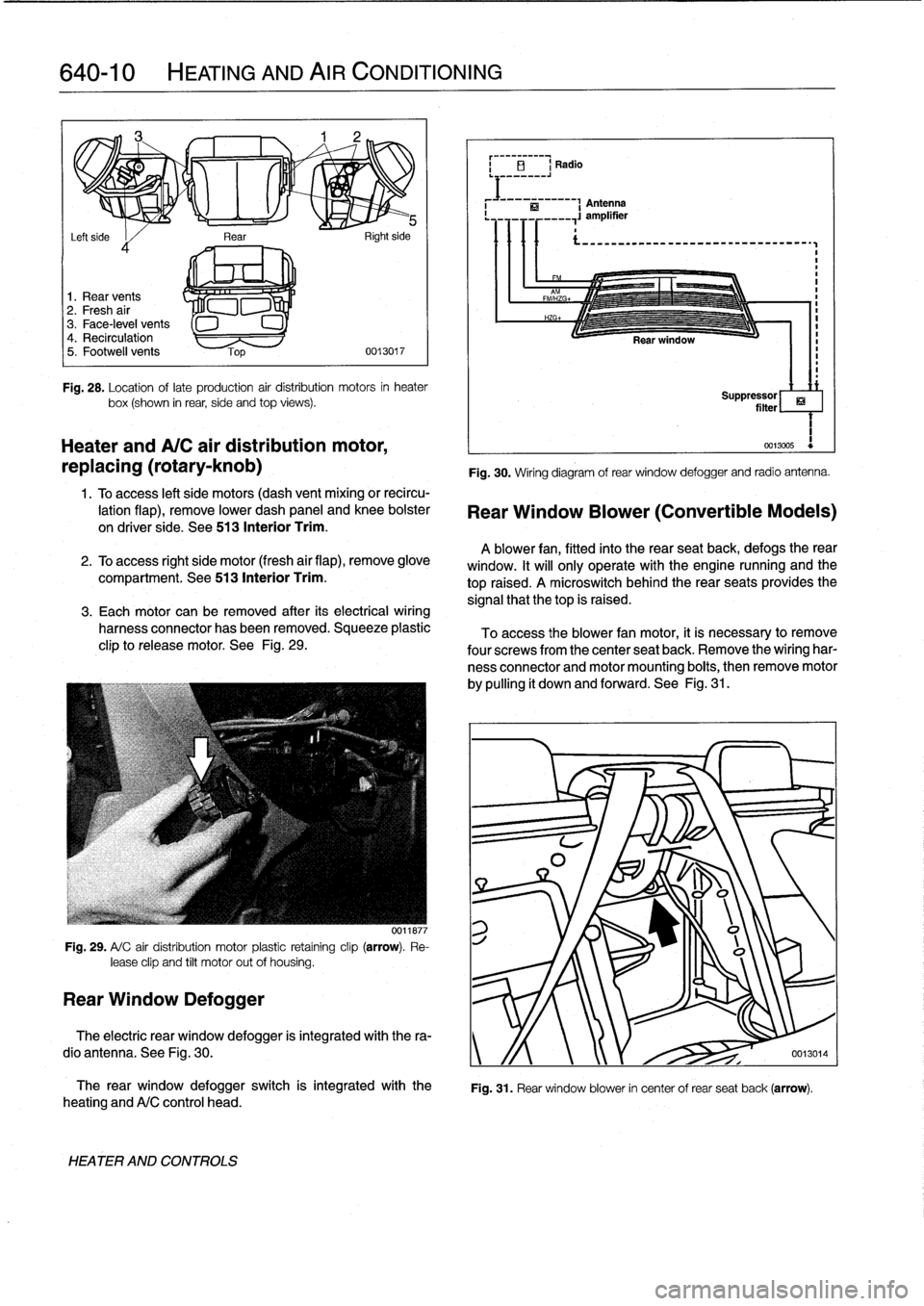
Fig
.
28
.
Location
oflate
production
air
distribution
motors
in
heater
box(shown
in
rear,
side
and
top
views)
.
Heater
andA/C
air
distribution
motor,
replacing
(rotary-knob)
1
.
Toaccess
left
side
motors
(dash
vent
mixing
or
recircu-
lation
flap),
remove
lower
dash
panel
and
knee
bolster
on
driver
side
.
See
513
Interior
Trim
.
2
.
To
access
right
side
motor
(fresh
air
flap),
remove
glove
compartment
.
See513
Interior
Trim
.
3
.
Each
motor
can
be
removed
after
its
electrical
wiring
harness
connector
has
been
removed
.
Squeeze
plastic
clip
to
release
motor
.
See
Fig
.
29
.
Fig
.
29
.
A/
C
air
distribution
motor
plastic
retaíning
clip
(arrow)
.
Re-
lease
clip
and
tilt
motor
out
of
housing
.
Rear
Window
Defogger
0011877
The
rear
window
defogger
switch
is
integrated
with
the
heating
andA/C
control
head
.
HEATER
AND
CONTROLS
Fig
.
30
.
Wiring
diagram
of
rear
window
defogger
and
radio
antenna
.
Rear
Window
Blower
(Convertible
Models)
A
blower
fan,
fitted
into
the
rear
seatback,
defogs
therear
window
.
It
will
only
operate
with
the
engine
nunning
and
the
top
raised
.
A
microswitch
behindthe
rear
seats
provides
the
signal
that
thetop
is
raised
.
To
access
the
blower
fan
motor,
it
is
necessary
to
remove
four
screwsfrom
the
center
seat
back
.
Remove
the
wiring
har-
ness
connector
and
motor
mounting
boits,
then
remove
motor
by
pulling
it
down
and
forward
.
See
Fig
.
31
.
ri
Suppressor
filter
1
0013005
Fig
.
31
.
Rear
window
blower
in
center
of
rear
seat
back
(arrow)
.
The
electric
rear
window
defogger
is
integrated
with
the
ra-
dio
antenna
.
See
Fig
.
30
.
y
/f
0013014
Page 457 of 759
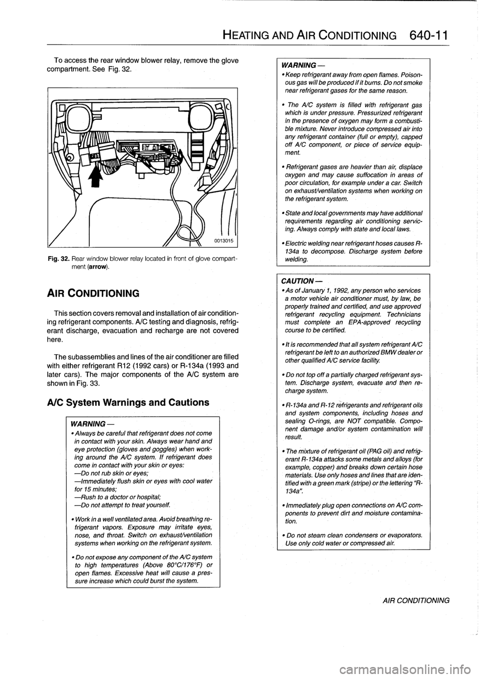
To
access
the
rear
window
blower
relay,
remove
the
glove
compariment
.
See
Fig
.
32
.
Fig
.
32
.
Rear
window
blower
relay
located
in
frontof
glove
compart-
ment
(arrow)
.
AIR
CONDITIONING
Thissection
covers
removal
and
installation
of
air
condition-
ing
refrigerant
components
.
A/C
testing
and
diagnosis,
refrig-
erantdischarge,
evacuatíon
and
recharge
are
not
covered
here
.
The
subassemblies
and
lines
of
the
air
conditionerare
filled
with
either
refrigerant
R12
(1992
cars)
or
R-134a
(1993
and
later
cars)
.
The
major
components
of
the
A/Csystem
are
shown
in
Fig
.
33
.
A/CSystem
Warnings
and
Cautions
WARNING
-
"
Always
be
careful
that
refrigerant
does
not
come
in
contact
with
your
skin
.
Always
wearhand
andeye
protection
(gloves
and
goggles)
when
work-
ing
around
the
AIC
system
.
If
refrigerant
does
come
in
contact
with
your
skin
oreyes
:
-Do
not
rub
skin
oreyes
;
-Immediately
flush
skin
oreyes
withcool
water
for
15
minutes
;
-Rush
to
a
doctor
orhospital
;
-Do
not
attempt
to
treat
yourself
.
"
Work
in
a
wefl
ventilated
area
.
Avoid
breathing
re-
frigerant
vapors
.
Exposure
may
irrítate
eyes,
nose,
and
throat
.
Switch
on
exhaustlventilation
systems
when
working
on
the
refrigerant
system
.
"
Do
not
expose
any
component
of
the
AIC
system
to
high
temperatures
(Above
80°Cl176°F)or
open
flames
.
Excessive
heat
will
cause
a
pres-
sureincrease
whichcould
burst
the
system
.
HEATING
AND
AIR
CONDITIONING
640-
1
1
0013015
WARNING
-
"
Keep
refrigerant
away
from
open
llames
.
Poison-
ous
gas
will
be
produced
if
it
bums
.
Do
not
smoke
near
refrigerant
gases
for
the
same
reason
.
"
The
AICsystem
is
filled
with
refrigerant
gas
which
is
under
pressure
.
Pressurized
refrigerant
in
the
presenceof
oxygen
may
forma
combusti-
ble
mixture
.
Never
introduce
compressed
air
finto
any
refrigerant
container
(full
or
empty),
capped
off
AIC
component,
or
piece
of
service
equip-
ment
.
"
Refrígerant
gases
are
heavier
than
air,
displace
oxygen
and
may
cause
suffocation
in
areas
of
poor
círculation,
for
example
under
a
car
.
Switch
on
exhaustlventilation
systems
when
working
on
the
refrigerant
system
.
"
State
and
local
governments
may
have
additional
requirements
regarding
air
conditioning
servic-
ing
.
Alwayscomply
with
state
and
local
laws
.
"
Electric
welding
near
refrigerant
hoses
causes
R-134a
to
decompose
.
Discharge
system
before
welding
.
CA
UTION
-
-As
of
January
1,
1992,
any
person
who
services
a
motor
vehicle
air
conditioner
must,
by
law,
be
properly
trained
and
certified,
and
use
approved
refrigerant
recycling
equipment
.
Technicians
must
complete
an
EPA-approved
recycling
course
to
be
certified
.
"
It
is
recommended
that
al¡
system
refrigerant
AIC
refrigerant
be
left
to
an
authorized
BMW
dealer
or
other
qualified
AIC
service
facility
.
"
Do
not
top
off
a
partially
charged
refrigerant
sys-
tem
.
Dischargesystem,evacuate
and
then
re-
charge
system
.
"
R-134a
and
R-12
refrigerants
and
refrigerant
oils
and
system
components,
including
hoses
and
sealing
O-rings,
are
NOT
compatible
.
Compo-
nent
damage
andlor
system
contamination
will
result
.
"
The
mixture
of
refrigerant
oil
(PAG
oil)
and
refrig-
erant
R-134a
attacks
some
metals
and
alloys
(for
example,copper)
and
breaks
down
certain
hose
materials
.
Use
only
hoses
and
lines
that
are
iden-
tified
with
a
green
mark
(stripe)
or
the
lettering
R-
134a"
.
"
Immediately
plug
open
connections
on
AIC
com-
ponents
to
prevent
dirt
and
moisture
contamina-
tion
.
"
Do
not
steam
clean
condensers
or
evaporators
.
Use
only
cold
water
or
compressed
air
.
AIR
CONDITIONING
Page 466 of 759
650-2
RADIO
"
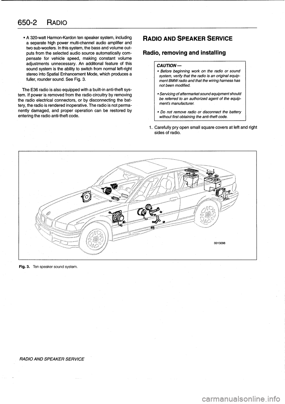
A
320-watt
Harmon-Kardon
ten
speaker
system,
including
RADIO
AND
SPEAKER
SERVICE
a
separate
high
power
multi-channel
audio
amplifier
and
two
sub-woofers
.
In
this
system,
thebass
and
volume
out-
puts
from
the
selected
audiosource
automatically
com-
Radio,
removing
and
installing
pensate
for
vehicle
speed,
making
constant
volume
adjustments
unnecessary
.
An
additional
feature
ofthis
CAUTION-
sound
system
is
the
ability
to
switch
from
normal
left-right
"
Before
beginning
work
on
the
radio
or
sound
stereo
into
Spatial
Enhancement
Mode,
which
produces
a
system,
verify
that
the
radio
is
an
original
equip-
fuller,
rounder
sound
.
See
Fig
.
3
.
ment
BMW
radio
and
that
thewiring
harness
has
not
been
modified
.
TheE36
radio
is
also
equipped
with
a
built-in
anti-theft
sys-
tem
.
lf
power
is
removed
from
the
radio
circuitry
by
removing
the
radio
electrical
connectors,
or
by
disconnecting
the
bat-
tery,
the
radio
is
rendered
inoperative
.
The
radio
is
not
perma-
nently
damaged,
and
proper
operation
can
be
restored
by
entering
the
radio
anti-theft
code
.
Fig
.
3
.
Ten
speaker
sound
system
.
RADIO
AND
SPEAKER
SERVICE
"
Servicing
of
aftermarket
sound
equipment
should
be
referredto
an
authorized
agent
of
the
equip-
ment's
manufacturer
.
"
Do
not
remove
radio
or
disconnect
the
batterywithout
first
obtaining
the
anti-theft
code
.
1.
Carefully
pry
open
small
square
covers
at
left
and
right
sides
of
radio
.
Page 478 of 759
721-2
AIRBAG
SYSTEM
(SRS)
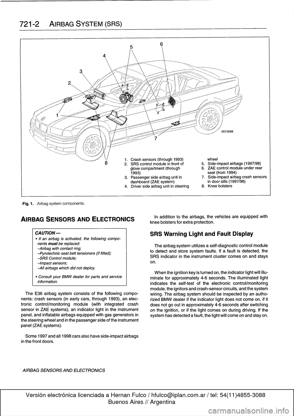
Fig
.
1
.
Airbag
system
components
.
AIRBAG
SENSORSAND
ELECTRONICS
CA
UTION-
"
If
an
airbag
is
activated,
the
following
compo-
nents
must
be
replaced
:
Airbag
with
contact
ring
;
-Pyrotechnic
seat
belt
tensioners
(if
fitted)
;
-SRS
Control
module
;
-Impact
sensors
;
All
airbags
which
did
not
deploy
.
"
Consult
your
BMW
dealer
for
parts
and
service
information
.
TheE36
airbag
system
consists
of
the
following
compo-
nents
:
crash
sensors
(in
earlycars,
through
1993),
an
elec-
tronic
control/monitoring
module
(with
integrated
crash
sensor
in
ZAE
systems),
an
indicator
light
in
the
instrument
panel,
and
inflatable
airbags
equipped
with
gas
generators
in
the
steering
wheel
and
in
the
passenger
side
of
the
instrument
panel
(ZAE
systems)
.
Some
1997
and
al¡
1998
carsalso
have
side-impact
airbags
in
the
front
doors
.
AIRBAG
SENSORS
AND
ELECTRONICS
1.
Crash
sensors
(through
1993)
wheel
2
.
SRS
control
module
in
front
of
5
.
Side-impact
airbags
(1997/98)
glove
compartment
(through
6
.
ZAE
control
module
under
rear
1993)
seat
(from
1994)
3
.
Passenger
side
airbag
unit
in
7
.
Side-impact
airbag
crash
sensors
dashboard
(ZAE
system)
in
door
silis
(1997/98)
4
.
Driver
side
airbag
unitin
steering
8
.
Knee
bolsters
In
addition
to
the
airbags,
the
vehicles
are
equipped
wíth
knee
bolsters
for
extra
protection
.
SRS
Warning
Light
and
Fault
Display
The
airbag
system
utilizes
a
self-diagnostic
control
module
to
detect
and
store
system
faults
.
If
a
fault
is
detected,
the
SRS
indicator
in
the
instrument
cluster
comes
on
and
stays
on
.
When
the
ignition
key
is
tumed
on,
the
indicator
light
will
illu-
minate
for
approximately
4-6
seconds
.
The
illuminated
light
indicates
the
self-testof
the
electronic
control/monitoring
module,
the
ignítors
and
crash-sensorcircuits,
and
the
system
wiring
.
The
airbag
system
should
be
inspected
byan
autho-
rized
BMW
dealer
if
the
indicator
light
does
not
come
on,
ifit
does
not
go
out
in
approximately
4-6
seconds
after
switching
onthe
ignition,
or
if
the
light
comes
on
during
driving
.
If
the
system
has
detected
a
fault,
the
light
will
come
on
and
stay
on
.
Page 485 of 759
GENERAL
This
section
contains
wiring
diagrams
for
1992
through
1998
BMW
3
Series
models
.
WARNING
-
On
cars
equipped
with
airbags,
special
precautions
apply
to
any
electrical
testing
or
repair
.
The
airbag
unit
is
an
explosive
device
and
must
be
handled
with
exterme
care
.
Before
starting
any
work
onan
airbag
equipped
car,
refer
to
the
warnings
and
cau-
tions
in
720
Seatbelts
and
721
Airbag
Systems
(SRS)
.
NOTE-
The
"
gear
position/neutral
safetyswitch
is
also
some-
timesreferred
to
as
the
automatic
transmission
range
switch
.
"
The
EWS
11
system
is
also
sometimes
referred
to
as
the
Driveaway
Protection
System
or
the
electronic
im-
mobilization
system
.
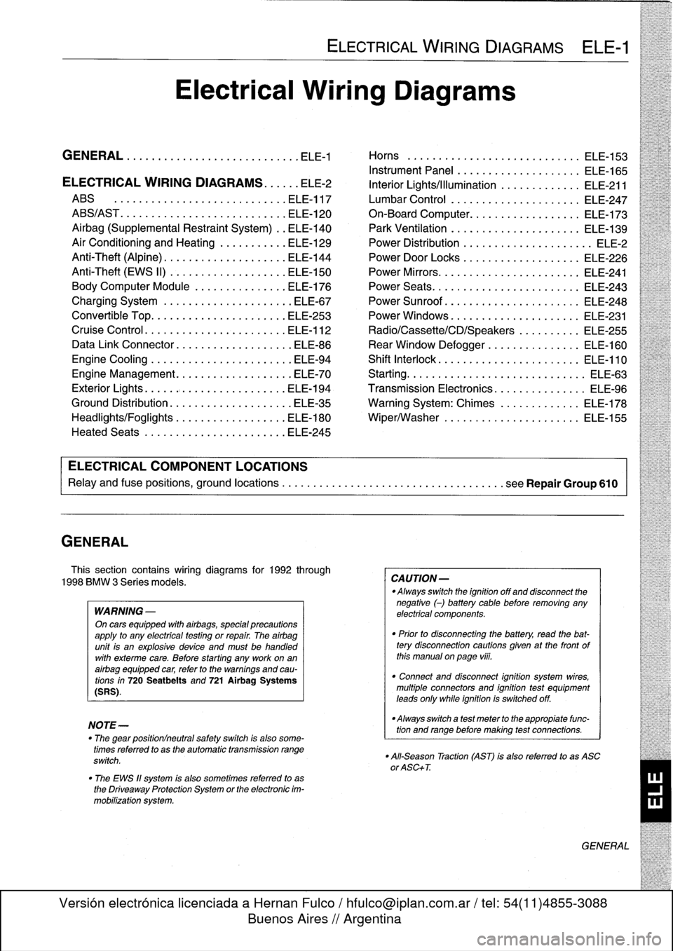
ELECTRICAL
WIRING
DIAGRAMS
ELE-1
Electrical
Wiring
Diagrams
GENERAL
.
.
.
.
.
.
.
.
.
................
.
.
.
ELE-1
Horns
.....
.
.....
.
.
.
....
.
.
.
.
.
...
.
.
ELE-153
Instrument
Panel
.
.
.
.
.
.
..............
ELE-165
ELECTRICAL
WIRING
DIAGRAMS
...
.
.
.
ELE-2
Interior
Lights/Illumination
.............
ELE-211
ABS
..............
.
.
.
.....
.
.....
ELE-117
Lumbar
Control
.
....................
ELE-247
ABS/AST
.............
.
.
.
...
.
.
.
.....
ELE-120
On-Board
Computer
..................
ELE-173
Airbag
(Supplemental
Restraint
System)
..
ELE-140
Park
Ventilation
.
.
.
...........
.
...
.
..
ELE-139
Air
Conditioning
and
Heating
.
.
.
.
.
.
.....
ELE-129
Power
Distribution
......
.
...
.
.
.
.
.
.
.
...
.
ELE-2
Anti-Theft
(Alpine)
..........
.
.
.
...
.
...
ELE-144
Power
Door
Locks
.
.
......
.
.
.
.
.
.
.
.
.
..
ELE-226
Anti-Theft
(EWS
II)
.
........
.
.
.
...
.
...
ELE-150
Power
Mirrors
...
.
.
.
......
.
.
.
.
.
.
.
.
.
..
ELE-241
Body
Computer
Module
.....
.
.....
.
...
ELE-176
Power
Seats
......
.
......
.
.
.
...
.
.
.
..
ELE-243
Charging
System
.
.
................
.
.
.
ELE-67
Power
Sunroof
.
.
.
.
.
.
.
...............
ELE-248
Convertible
Top
.
.
.
.
................
.
.
ELE-253
Power
Windows
.
.
.
.
.
.
.....
.
.........
ELE-231
Cruise
Control
..
.
.
.
...........
.
....
.
.
ELE-112
Radio/Cassette/CD/Speakers
..........
ELE-255
Data
Link
Connector
................
.
.
.
ELE-86
Rear
Window
Defogger
...............
ELE-160
Engine
Cooling
.......
.
.......
.
....
.
.
.
ELE-94
Shift
Interlock
.
.
.
.
.
.
.
.
...............
ELE-110
Engine
Management
...
.
.......
.
....
.
.
.
ELE-70
Starting
....
.
.
.
.
.
...
.
................
ELE-63
Exterior
Lights
........
.
.
.
.
.
.
.
.
.
......
ELE-194
Transmission
Electronics
.
..............
ELE-96
Ground
Distribution
....
.
.
.
.
.
.
.
.
.
.......
ELE-35
Warning
System
:
Chimes
.............
ELE-178
Headlights/Foglights
...
.
.
.
.
.
.
.
.
.
......
ELE-180
Wiper/Washer
.
.....
.
...............
ELE-155
Heated
Seats
........
.
.
.
.
.
.
.
.
.
......
ELE-245
ELECTRICAL
COMPONENT
LOCATIONS
Relayand
fuse
positions,
ground
locations
...........
.
.
.
.
.
.
.
.
.
................
seeRepair
Group
610
CAUTION-
Always
switchthe
ignition
off
and
disconnect
the
negative
(-)
battery
cablebefore
removing
any
electrical
components
.
"
Prior
to
disconnecting
the
battery,
read
the
bat-tery
disconnection
cautions
given
at
the
front
of
this
manual
on
page
viii
.
"
Connect
and
disconnect
ignition
system
wires,
multiple
connectors
and
ignition
test
equipment
leads
only
while
ignition
is
switched
off
.
-Always
switch
a
test
meter
to
the
appropiate
func-
tion
and
range
before
making
test
connections
.
"
All-Season
Traction
(AST)
is
also
referred
to
as
ASC
or
ASC+T
.
GENERAL
Page 486 of 759
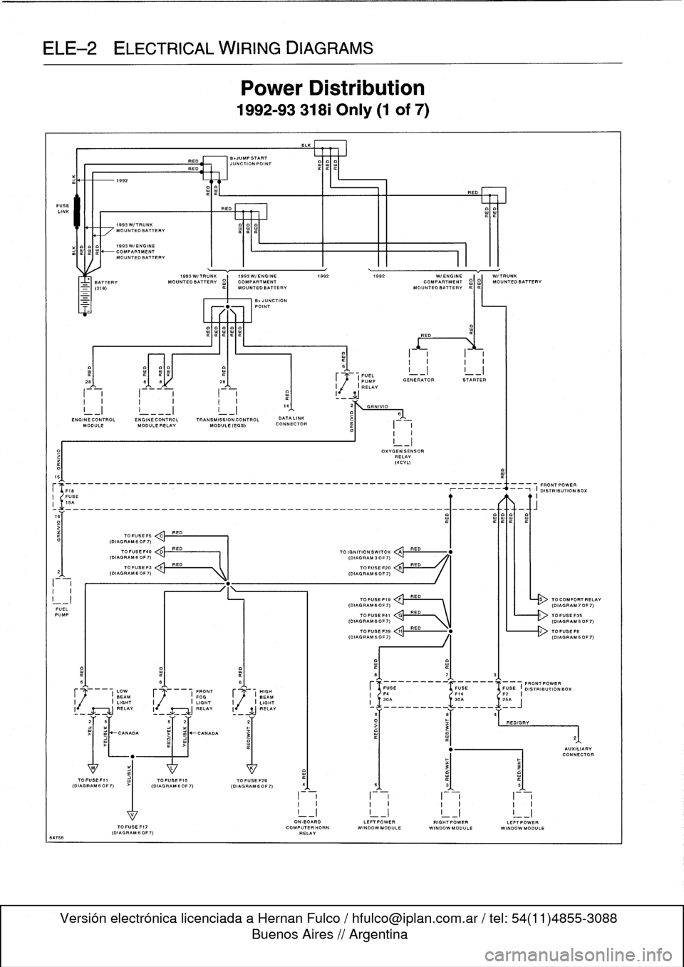
ELE--2
ELECTRICAL
WIRING
DIAGRAMS
FUSE
LINK
64766
I-i
I
-
i
a
1
I
_
ZJ
I
I
I
I
I
I.
4
2
GRN/VIO
I_I
!
___I
I_I
1
D>
6
END
INECONTROL
ENGINECONTROL
TRANSMISSION
CONTROL
DATALINK
MODULE
MODULE
RELAY
MODULE
(EGS)
CONNECTOR
I
I
I
I
5
(F18
--_______________________________________________
O19~
N
RIBUON
BOX
I
FUSE
II
15A
o~___________________________________________________Q~____-aft
TO
FUSE
F5
C
RED
(DIAGRAM
6
OF
7)
FUELPUMP
I
(DIAGRAM60F7)
C'
RED
\
L------r>
(DIAGRAM60F7)
I
LOW
F
I
FRONT
HIGH
BEAM
FOGJ
BEAM
I
I
LIGHT
I
I
LIGHT
I
j
/
I
LIGHT
RELAY
I
RELAY
li
SJ
RELAY
1992
1993W/TRUNK
MOUNTEDBATTERV
1993W/ENGINE
COMPARTMENTMOUNTEDBATTERV
1993W/TRUNK
1993W/ENGINE
1992
1992
WI
ENGINE
W/TRUNK
BATTERY
MOUNTEDBATTERV
¢)
MOUNTED
BATTERY
MOUN
O
TEDBATT
I
ERV
¢I¢I
MOUNTEDBATTERV
TOFUSEF40
<
,.k
RED
(DIAGRAM
6
OF
7)
I
I
(DIAGRAM
3
OF
7)
TO
FUSEF3
E
RED
(DIAGRAMfiOF7)
"
.
1k
I
(DIAGRAM
6OF7)
>I
mJ~CANADA
RED
BNUMPSTART
JUNCTION
POINT
REO
Power
Distribution
1992-93
318i
Only
(1
of
7)
-UNCTION
POINT
TOFUSEF15
TO
FUSE
F29
(DIAGRAM60F7)
(OIAGRAM6OF7)
I
~1
.
FUEL
_I
I
_I
~
(PUMP
GENERATOR
STARTER
I
,(
I
RELAY
TO
IGNITION
SWITCH
QA
TOFUSE
F20
TOFUSEF19
FRED
(DIAGRAM6OF7)
`
I
III
-
(DIAGRAM70F7)
OXVGENSENSOR
RELAY
(4CVL)
RED
RED
RED
ON-BOARD
LEFTPOWERRIGHTPOWERLEFTPOWER
TOFUSEF17
COMPUTERHORN
WINDOWMODULE
WINDOWMODULE
WINDOW
MODULE
(DIAGRAM
60F
7)
RELAY
TO
COMFORTRELAV
Page 487 of 759
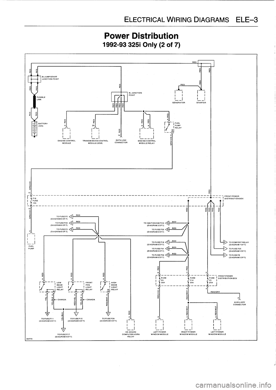
ELE
Power
L
1992-9332
RED
E01
IIIII
FUSIBLE
LINK
I
GENERATOR
STARTER
BATTERY
¢
(FUEL
-
(325)
S
26
66
PUMP
I
I
RELAY
2
G
ENGINE
CONTROL
TRANSMISSION
CONTROL
DATA
LINK
ENGINECONTROL
iMODULE
MODULE
(EGG)
CONNECTOR
MODULE
RELAY
15
--
---
-
-
----
--
FRONT
POWER
FUSE
r
-
i
DISTRIBUTIONBO
;
I
16A
R
ITIT
TO
FUSE
FS
ED
C
(DIAL
RAM
6
OF
7)
TO
FUSE
F40
D
RED
TO
IGNITION
SWITCH
A
RED
(DIAGRAM
6
OF
7)
(DIAGRAM
3
OF
7)
TO
FUSE
F3
E
RED
TO
FUSE
F20
B
RED
2
(DIAGRAM6OF7)
(DIAGRAM
6OF7)
I
I
I
I
-
I
TOFUSEF19
:
:!!RED---
RED
S
TOCOMFORTI
(DIAGRAM
6
OF
7)
(DIAGRAM
70
FUEL
PUMP
TO
FUSE
F41
V\
TOFUGEF35
(DIAGRAM
B
OF
7)
\
(DIAGRAM
50
TOFUSEFSB
H
RED
"
J
TOFUSEF
.
(DIAGRAM
6
0F
7)
(DIAGRAM
50
8
7
3
FUGE
FUSE
FUSE
I
FRONT
POWER
B
6
6
DISTRIBUTION
BOX
F4
F14
F2
I
LOW
FRONT
HIGH
I
30A
30A
~
.1
.
25A
BEAM
F
I
FOG
F
(
BEAM
i
_________
_____
J
I
I
LIGHT
I
I
LIGHT
I
.
I
LIGHT
l
RELAY
I
-
RELAY
I
-
WJ
_RELAY
6
B
4
-
-
-
O
RED/GRY
3
21
2
B
62
2
~
-
CANADA
j
m
-CANADA
3
"
AUXILIAI
CONNECT
"
3
3
M
L
K
4(D
IAGAGR
AM60
F7)
(DIAGRAM
IAGRAM
B
OFOF
7)
(DIAGRAM
6
0
6
3
3G
FO
F
~
7)
I
I
I
I
I
II
I
I
I
I
I
I
I
!
_I
!
_I
!
_I
!
_
17
I
ON-BOARD
LEFTPOWER
RIGHTPOWER
LEFT
POWERTOFUSEFI7
COMPUTERHORN
WINDOW
MODULE
WINDOWMODULE
WI
NDOWMODULE
(DIAGRAMS
OF7)
RELAY
64770
Page 489 of 759
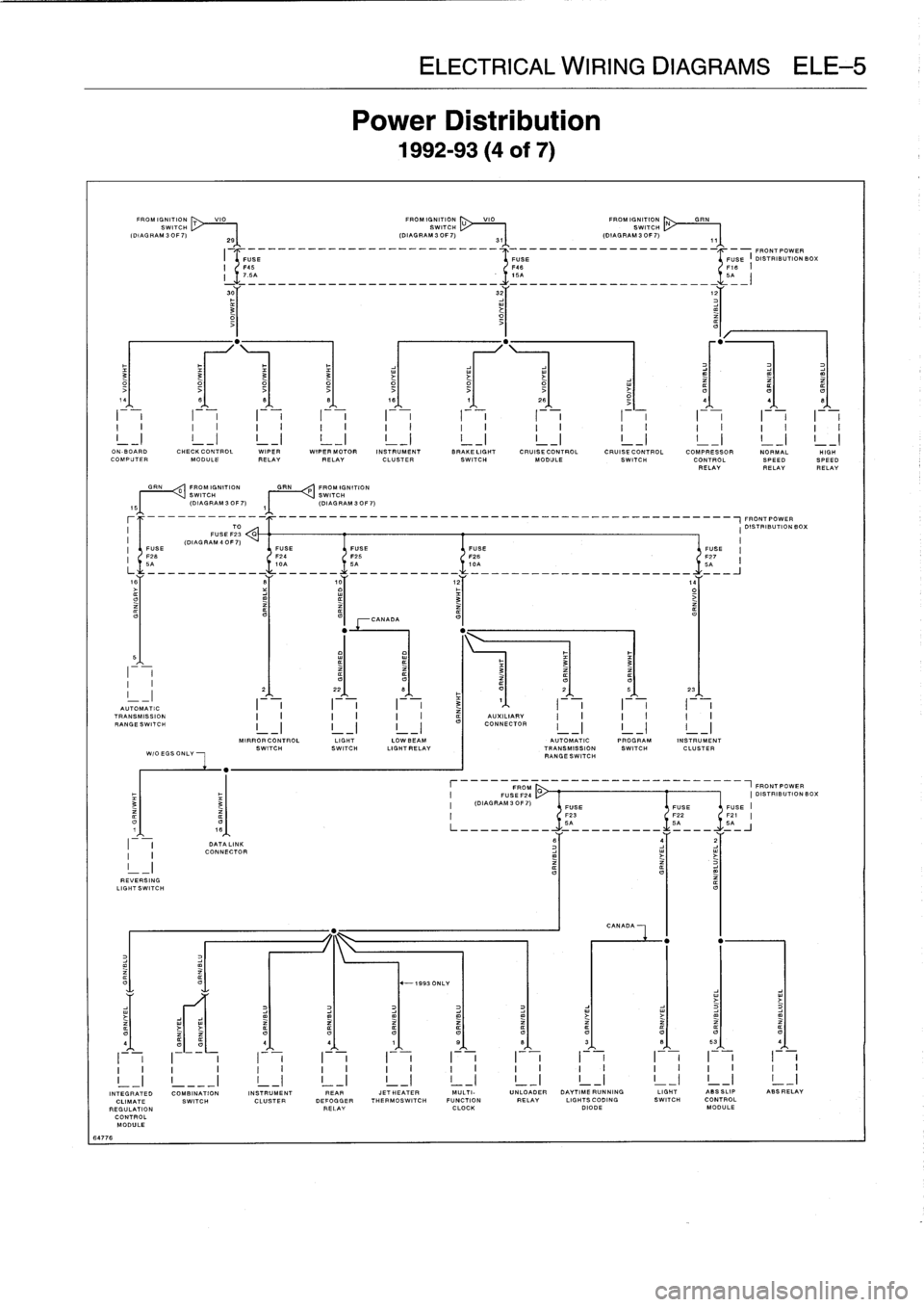
EKE
Power
1992-
VIO
FROMIGNITION
U
VIO
FROM
IGNITI
ON
SWITCH
SWITCH
2S
(DIAGRAM3OF7)
31
(DIAGRAM3OF7)
I
-
______________-__________--
4
-_____________________I_-FRONT
POWER
O
3
3
3
3
i
14
8
8
B
18
7
26
-
4
4
I
i
I
I
i
-F-
I
i
I
-
,
I
,
I
I
F-,
ON
-BOARD
CHECKCONTROL
WIPER
WIPER
MOTOR
INSTRUMENT
BRAKELIGHT
CRUISE
CONTROL
CRUISE
CONTROL
COMPRESSOR
NORMALCOMPUTER
MODULE
RELAYRELAY
CLUSTER
SWITCH
MODULE
SWITCH
CONTROL
SPEEDRELAYRELAY
GRN
0
FROM
IGNITION
GRN
P
FROM
IGNITION
~I
I
VSWITCH
SWITCH
(DIAGRAM
30F7)
,~
(DIAGRAM
3OF7)
-------_-_____________________________________________~FRONT
POWER
TO
I
DISTRIBUTIONBOX
FUSE
F23
G
(DIAG
RAM
4
0F
7)
I
FUSE
FUSE
FUSE
FUSE
FUSE
'
F26
F24
F25
F26
-
F27
6A
10A
SA
ICA
5A
is
S
,0
12
,4
o3
>
CANADA
5
I
~
~
~
3
33
-
2
22
B
F
O
2
5
23
AUTOMATIC
I
I
I
3
1
I
TRANSMISSION
AUXILIARY
RANGESWITCH
I
-
I
I
-
I
I
-
I
CONNECTOR
MIRRORCONTROL
LIGHT
LOWBEAM
AUTOMATIC
PROGRAM
INSTRUMENT
SWITCHSWITCH
LIGHTRELAY
TRANSMISSION
SWITCH
CLUSTER
WIOEGSONLY
RANGESWITCH
FROM
___________-----1FRONTPOWER
FUSEF24
CI
DISTRIBUTION
BC
3
(DIAGRAM30F7)
FUSE
FUSEFUSE
F23
F22
F21
O
O
SA
SA
5A
DATA
LINK
6
j
2
I
CONNECTOR
REVERSING
LIGHTSWITCH
CANADA
O
"
-1993
ONLY
O4
4
4
1
S
B
3
B
53
4
I
v
I~
i
I
i
I
v
I
i
I
v
I
i
I
v
I
i
I
i
I
i
v
v
v
v
~
v
v
~
~
v
v
~
v
v
o
n
v
v
v
v
v
v
_I
INTEGRATED
COMBINATION
INSTRUMENT
REAR
JETHEATER
MULTI-
UNLOADER
DAYTIMERUNNING
LIGHT
ASSSLIP
ABSRELAY
CLIMATE
SWITCH
CLUSTER
DEFOGGER
THERMOSWITCH
FUNCTION
RELAY
LIGHTSCODING
SWITCH
CONTROL
REGULATION
RELAY
CLOCK
DIODE
MODULE
CONTROL
MODULE
64776