glove compartment BMW 318i 1997 E36 Workshop Manual
[x] Cancel search | Manufacturer: BMW, Model Year: 1997, Model line: 318i, Model: BMW 318i 1997 E36Pages: 759
Page 26 of 759
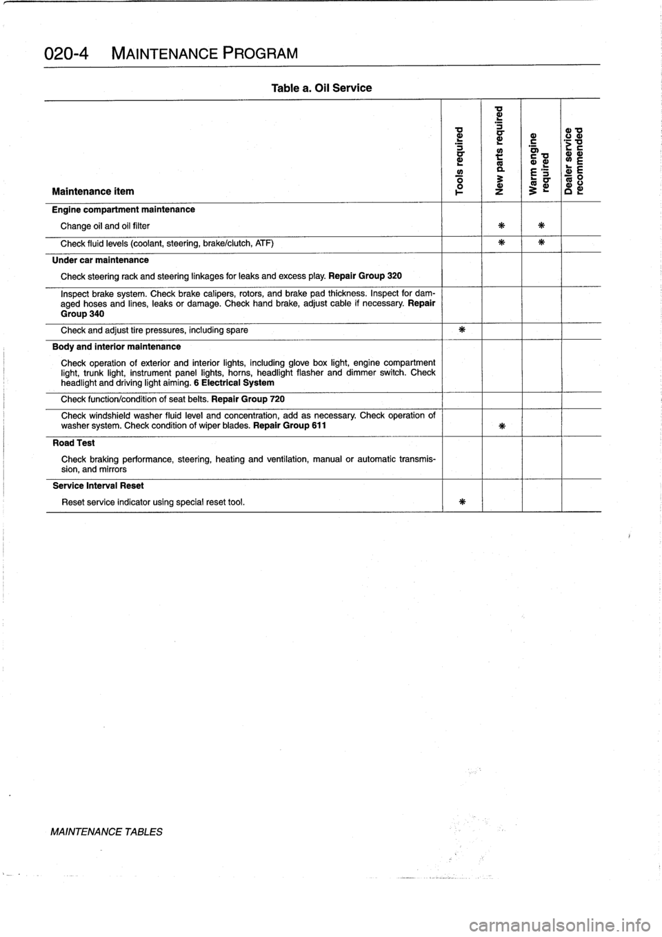
020-
4
MAINTENANCE
PROGRAM
L
~
~
c
.c
a
a>
mL
~
~L
L
w
a
£
'S
d
E
Maintenance
ítem
z
3
c
Engine
compartment
maintenance
Change
oil
and
oil
filter
Check
fluid
levels
(coolant,steering,
brake/clutch,
ATF)
Under
car
maintenance
Check
steeringrack
and
steeringlinkages
for
leaks
andexcess
play
.
Repair
Group
320
Inspect
brake
system
.
Check
brake
calipers,
rotors,
and
brake
pad
thíckness
.
Inspect
for
dam-
aged
hoses
and
lines,
leaks
or
damage
.
Check
hand
brake,adjust
cable
if
necessary
.
Repair
Group
340
Check
and
adjust
tire
pressures,
including
spare
Body
and
interior
maintenance
Check
operation
of
exterior
and
interior
lights,
including
glove
box
light,
engine
compartment
light,
trunk
light,
instrument
panel
lights,
horns,
headlight
flasher
anddimmer
switch
.
Check
headlight
and
driving
light
aiming
.
6
Electrical
System
Check
function/condition
of
seat
belts
.
Repair
Group
720
Check
windshield
washer
fluid
level
and
concentration,
add
as
necessary
.
Check
operation
of
washer
system
.
Check
condition
of
wiper
blades
.
Repair
Group
611
Road
Test
Check
braking
performance,
steering,
heating
and
ventilation,
manual
or
automatic
transmis-
sion,
and
mirrors
Service
Interval
Reset
Reset
service
indicator
using
specialreset
tool
.
MAINTENANCE
TABLES
Table
a
.
Oil
Service
Page 27 of 759
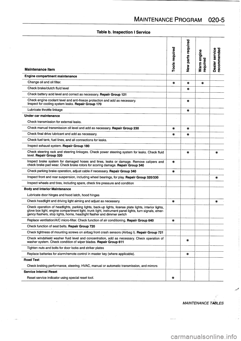
Table
b
.
Inspection
I
Service
MAINTENANCE
PROGRAM
020-5
ad
d
d
ID
a
r
c
d
a~
;v
a
:
Q~
wE
y
a
r
E
R
:
L-
0
Maintenance
ítem
1
z
3
~
c
d
Engine
compartment
maintenance
Change
oil
and
oil
filter
.
Check
brake/clutch
fluid
leve¡
Check
battery
acid
leve¡
and
correct
asnecessary
.
Repair
Group
121
Check
engine
coolant
level
and
anti-freeze
protection
and
addasnecessary
.
Inspect
for
cooling
system
leaks
.
Repair
Group
170
Lubricate
throttie
linkage
Under
car
maintenance
Check
transmission
for
externa¡
leaks
.
Check
manual
transmission
oil
leve¡
andadd
asnecessary
.
Repair
Group
230
Check
final
drive
lubricant
and
addasnecessary
.
Check
fue¡
tank,
fuel
lines,
and
all
connections
for
leaks
.
Inspect
exhaust
system
.
Repair
Group
180
Check
steeringrack
and
steeringlinkages
.
Check
power
steering
system
for
leaks
.
Check
(luid
leve¡
.
Repair
Group
320
Inspect
brake
system
for
damaged
hoses
and
fines,
leaks
or
damage
.
Remove
calipers
and
check
brake
pad
wear
.
Check
brake
rotors
for
scoring
damage
.
Repair
Group
340
Check
parking
brake
operation,
adjust
cable
if
necessary
Repair
Group
340
Inspect
front
and
rear
suspension,
including
wheel
bearings,
for
play
.
Repair
Group
320/330
Inspect
wheelsand
tires,
including
spare,
check
tire
pressure
and
condition
Body
and
Interior
Maintenance
Lubricate
door
hinges
and
hood
latch,
hood
hinges
Check
headlight
and
driving
light
aiming
and
adjust
as
necessary
.
Check
operation
of
headlights,
parking
lights,
back-up
fights,
licenseplate
lights,
interior
lights,
glove
box
light,
engine
compartment
light,
trunk
light,
instrument
panel
lights,
turnsignals,
emer-gency
flashers,
stop
fights,
horas,
headlight
flasher
and
dimmer
switch
Replace
ventilation/A/C
micro-filter
.
Check
functionof
air
conditioning
.
Repair
Group
640
Check
function
of
seat
belts
.
Repair
Group
720
Check
tightness
of
mountfng
screws
on
airbag
front
crash
sensors
(Airbag
I)
.
Repair
Group
721
Check
windshield
washer
fluid
leve¡
and
concentration,
add
as
necessary
Check
operation
of
washer
system
.
Check
condition
of
wiperblades
.
Repair
Group
611
Tighten
nuts
and
bolts
for
door
locks
and
striker
plates
Replace
batteries
for
alarm/remote
control
in
masterkey(where
applicable)
.
Road
Test
Check
braking
performance,
steering,
HVAC,
manual
or
automatic
transmission,
and
mirrors
Service
Interval
Reset
Reset
service
indicator
using
specialreset
tool
.
MAINTENANCE
TALES
Page 28 of 759
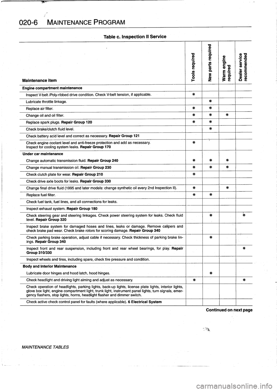
020-6
MAINTENANCE
PROGRAM
Group
310/330
Table
c
.
Inspection
II
Service
a
d
d
a
a>
0
d
a
r
.c
mm
L
m
y
L
E
ó
3
E
ó
Maintenance
ítem
l
o-
z
~
c
Engine
compartment
maintenance
Inspect
V-belt
/Poly-ribbeddrive
condition
.
Check
V-belt
tension,
if
applicable
.
Lubricate
throttle
linkage
.
Replace
air
filter
.
Change
oil
and
oil
filter
.
Replacespark
plugs
.
Repair
Group
120
Check
brake/clutch
fluid
leve¡
.
Check
battery
acid
leve¡
and
correct
asnecessary
.
Repair
Group
121
Check
engine
coolant
leve¡
and
anti-freeze
protection
and
add
asnecessary
.
Inspect
for
cooling
system
leaks
.
Repair
Group
170
Under
car
maintenance
Change
automatic
transmission
fluid
.
Repair
Group
240
Change
manual
transmission
oil
.
Repair
Group
230
Check
clutch
plate
for
wear
.
Repair
Group
210
Check
drive
axle
boots
for
leaks
.
Repair
Group
330
Change
final
drive
fluid
(1995
and
later
models
:
change
synthetic
oil
every
2nd
Inspection
II)
.
Replace
fuel
filter
.
Check
fuel
tank,
fuel
lines,
and
af
connections
for
leaks
.
Inspect
exhaust
system
.
Repair
Group
180
Check
steering
gear
and
steering
¡inkages
.
Check
power
steering
system
for
leaks
.
Check
fluidleve¡
.
Repair
Group
320
Inspect
brake
system
for
damaged
hoses
and
lines,
leaks
or
damage
.
Remove
calipers
and
check
brake
pad
wear
.
Check
brake
rotors
for
scoring
damage
.
Repair
Group
340
Check
parking
brake
operation,
adjust
cable
if
necessary
.
Check
thickness
of
parking
brake
lin-
ings
.
Repair
Group
340
Inspect
front
and
rear
suspension,
including
front
and
rear
wheel
bearings,
for
play
.
Repair
Inspect
wheels
and
tires,
including
spare,
check
tire
pressure
and
condition
.
Body
and
Interior
Maintenance
Lubricate
door
hinges
and
hood
latch,
hood
hinges
.
Check
headlight
and
driving
light
aiming
and
adjust
asnecessary
.
Check
operation
of
headlights,
parking
lights,
back-up
lights,
licenseplate
lights,
interior
lights,
glove
box
light,
engine
compartment
light,
trunk
light,
instrument
panel
lights,
turn
signals,
emer-gency
flashers,
stop
lights,
horns,
headlight
flasher
anddimmer
switch
.
Check
active
check
control
panel
forfauits
(where
applicable)
.
6
Electrical
System
MAINTENANCE
TABLES
Continued
on
next
page
Page 32 of 759
020-
1
0
MAINTENANCE
PROGRAM
1.
Run
engine
for
afewminutes
to
warm
engine
oil
.
Shut
5
.
When
oil
flow
has
diminished
to
an
occasional
drip,
re-
engine
off
.
install
drain
plugwith
a
new
metal
sealing
washerand
torque
plug
.
2
.
With
car
on
level
ground,
place
drain
pan
under
oil
drain
plug
.
See
Fig
.
5
.
Tightening
Torques
"
Engine
oil
drain
plug
M12
bolt
(17mm
wrench)
.
...
.
..
.
25
Nm
(18
ft-Ib)
-
M22
bolt
(19mm
.
wrench)
...
.
...
.
60
Nm
(44
ft-Ib)
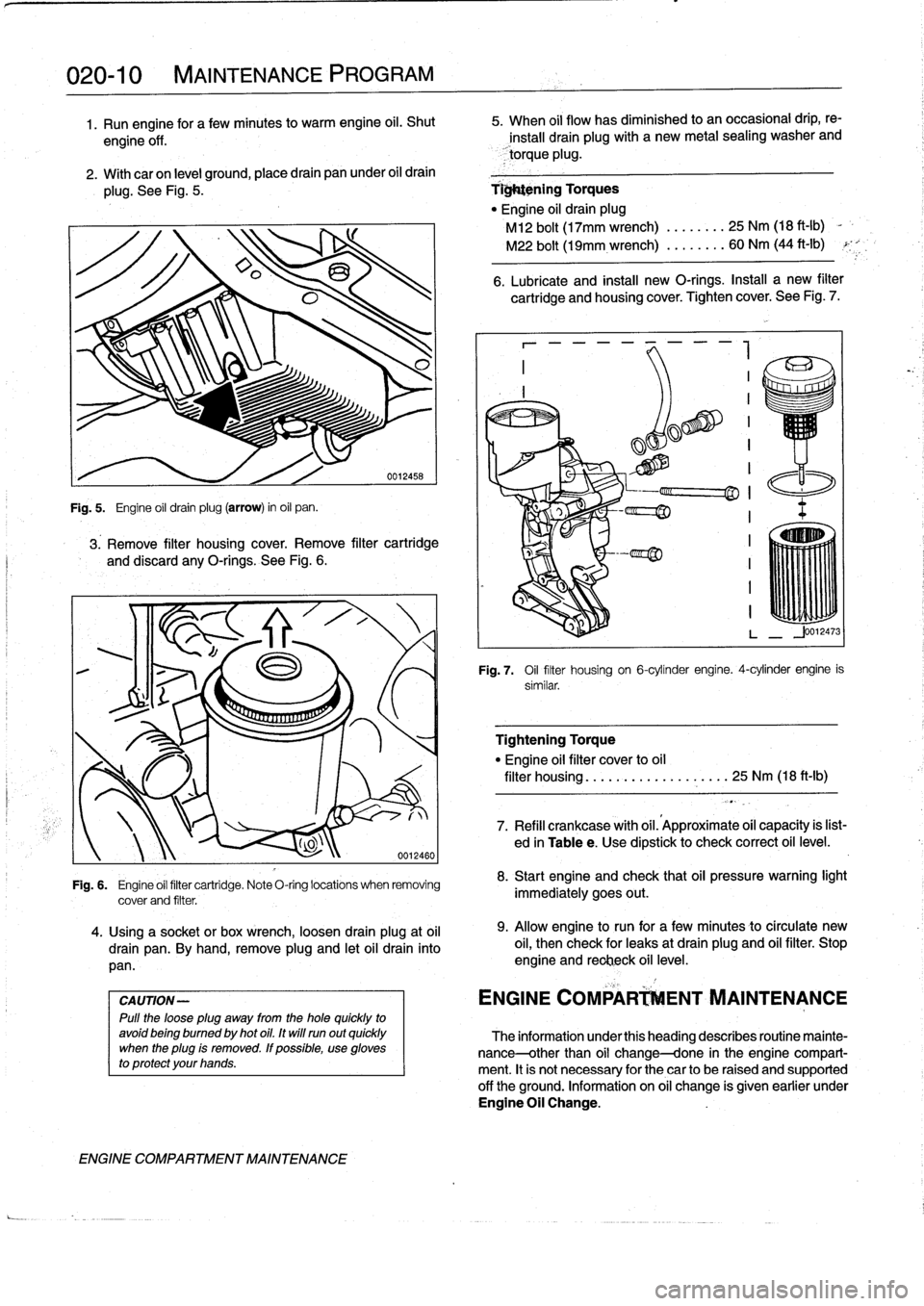
Fig
.
5
.
Engine
oil
drain
plug(arrow)
in
oil
pan
.
3
.
Remove
filter
housingcover
.
Remove
filter
cartridge
and
discard
any
O-rings
.
See
Fig
.
6
.
CAUTION-
Pulí
the
loose
plug
away
from
the
hole
quickly
to
avoidbeing
bumed
by
hot
oil
.
It
wíll
runout
quickly
when
the
plug
ís
removed
.
If
possible,
use
gloves
to
protect
your
hands
.
ENGINE
COMPARTMENT
MAINTENANCE
0012460
Fig
.
6
.
Engine
oil
filter
cartridge
.
Note
O-ring
locations
when
removing
cover
and
filter
.
4
.
Using
a
socket
or
box
wrench,
loosen
drain
plug
at
oil
drain
pan
.
By
hand,
remove
plug
and
letoil
drain
into
pan
.
6
.
Lubricate
and
install
new
O-rings
.
Install
a
new
filter
cartridge
and
housingcover
.
Tighten
cover
.
See
Fig
.
7
.
7
«
a~
.~~
fT~
iII~IIIi~
.
Fig
.
7
.
Oil
flter
housing
on
6-cylínder
engine
.
4-cylinder
engine
is
similar
.
Tightening
Torque
"
Engine
oil
filter
cover
to
oil
filter
housing
...................
25
Nm
(18
ft-Ib)
7
.
Refill
crankcase
with
oil
.'Approximate
oil
capacity
is
list-
ed
in
Tablee
.
Use
dipstick
to
check
correct
oil
level
.
8
.
Start
engine
and
check
that
oil
pressure
warning
light
immediately
goes
out
.
9
.
Allow
engine
to
run
for
a
few
minutes
to
círculate
new
oil,
then
check
for
leaks
at
drain
plug
and
oil
filter
.
Stop
engine
and
reclieck
oil
level
.
ENGINE
COMPAR
ENT
MAINTENANCE
The
information
underthis
heading
describes
routine
mainte-
nance-other
than
oil
change-done
in
the
engine
compart-
ment
.
It
is
not
necessary
for
the
car
to
be
raised
and
supported
off
the
ground
.
Information
on
oil
change
is
given
earlier
under
Engine
Oil
Change
.
Page 137 of 759
CHARGING
SYSTEM
TROUBLESHOOTING
.............
.
.
.
.
.121-2
Charging
System
Quick-Check
...
.
..
.
...
.
121-2
Static
current
draw,
checking
........
.
...
.
121-2
BATTERY
SERVICE
....................
121-3
Battery
Testing
.
.
.
.
.
.........
.
........
.
121-3
Hydrometer
Testing
.
...
.
.
.
...
.
.........
121-3
Battery
Open-Circuit
Voltage
Test
....
.
....
121-4
Battery
Load
Voltage
Test
.
.
.
.
.
.
.........
121-4
Battery
Charging
.
.
.
.
...
.
.
.
.
.
.
.
.........
121-4
ALTERNATOR
SERVICE
.
.
.
.
.
.
.....
.
...
121-4
Chargingsystem,checking
.
.
.
.
.
.........
121-4
Alternator,
removingand
installing
(4-cylinder
engine)
....
.
.
.
.
.
.
.
.........
121-5
Alternator,
removingand
installing
(6-cylinder
engine)
..
.
.
.
.
.
.
.
.
.
.........
121-6
GENERAL
The
charging
system
consists
of
a
belt-driven
alternator
with
integral
voltage
regulator
and
a
battery
mounted
in
the
luggage
compartment
.
Various
versions
of
alternators,
voltage
regulators,
starters,
and
batteries
are
used
in
the
E36
cars
.
It
is
important
to
re-
place
components
according
tothe
original
equipment
speci-
fication
.
Check
with
an
authorized
BMW
dealer
for
specific
application
and
parts
information
.
WARNING
-
"
Weargoggles,
rubbergloves,
and
a
rubberapron
when
working
around
batteries
and
battery
acid
(electrolyte)
.
"
Battery
acid
contains
sulfuric
acid
and
can
cause
skin
irritation
and
burning
.
ff
acid
is
spilled
onyour
skin
or
clothing,
flush
the
area
at
once
with
large
quantities
of
water
.
lf
electrolyte
gets
into
your
eyes,flush
them
with
largequantities
of
clean
wa-
terfor
several
minutes
and
call
a
physician
.
"
Batteries
that
are
being
charged
or
are
fully
charged
give
off
explosive
hydrogen
gas
.
Keep
sparks
and
open
flames
away
.
Do
not
smoke
.
BATTERY,
STARTER,
ALTERNATOR
121-1
121
Battery,
Starter,
Alternator
GENERAL
..
.
...
.
........
.
...
.
.
.
.
.
.
.
.
.
121-1
Voltage
regulator,
removing
and
ínstalling
.
.
.
121-6
Alternator
brushes,
inspecting
and
replacing
.121-7
STARTER
SERVICE
....
.
.
.
.
.
..........
.121-7
Starter
Troubleshootíng
121-7
15
..
.
.
.
.
.
........
.
.
.
Starter,
removing
and
installing
(4-cylinder
engine)
....
.
.
.
............
.
121-8
Starter,
removing
and
installing
(6-cylinder
engine
with
manual
transmission)
..
.
...........
.
...
121-8
Starter,
removing
and
installing
(6-cylinder
engine
with
automatic
transmission)
................
121-9
Solenoid
switch,
removingand
installing
....
121-10
TABLES
a
.
Battery,
Starter
and
Charging
System
Troubleshooting
............
.
.
.
.
:...
........
121-2
b
.
Specific
Gravity
of
Battery
Electrolyte
at
80°F
(27°C)
...............
.
.
..
..........
121-3
c
.
Open-Circuit
Voltage
and
Battery
Charge
........
121-4
d
.
Battery
Load
Test-Minimum
Voltage
.
..........
121-4
CAUTION
-
"
Prior
to
disconnectiog
the
battery,
read
the
bat-tery
disconnection
cautions
given
at
the
front
of
this
manual
on
page
viii
.
"
Disconnecting
the
battery
cables
may
erase
fault
codes
stored
in
control
unit
memory
.
"
Always
disconnect
the
negative
()
battery
cable
first
and
reconnect
it
last
.
Cover
the
battery
post
with
an
insulating
material
whenever
the
cable
is
removed
.
"
After
reconnecting
the
battery,
the
power
window
motors
must
be
reinitialized
.
See
511
Door
Win-
dows
.
"
Never
reverse
the
battery
cables
.
Even
a
momen-
tary
wrong
connection
can
damage
the
alternatoror
other
electrical
components
.
"
Battery
cables
may
be
the
same
color
.
Label
ca-blebefore
removing
.
GENERAL
Page 196 of 759
170-2
RADIATOR
AND
COOLING
SYSTEM
Cooling
Fans
TROUBLESHOOTING
Belt-driven
coolingfan
.
The
primary
cooling
fan
is
belt-
driven
.
It
is
mounted
to
the
frontof
the
coolant
pump
through
a
fan
clutch
.
The
fan
clutch
is
a
viscous
fluid
coupling
that
con-
trols
the
speed
of
thefan
based
on
engine
compartment
tem-
perature
.
Electric
cooling
fan
.
Models
with
M44
engine
and
stan-
dard
transmission
substitute
an
electric
fan
for
the
belt-driven
viscous
fan
.
This
is
attached
to
the
rear
of
the
radiator
and
controlledvia
the
DME
5
.2
engine
management
system
.
NOTE-
The
electric
cooling
fan
in
these
models
is
activated
by
the
engine
control
module
(ECM)
.
Auxiliary
coolingfan
.
In
al¡
models
a
two-speed
electric
auxiliary
cooling
fan
is
mounted
behind
the
front
grill
and
in
front
of
the
radiator
.
This
fan
is
primarily
used
for
the
A/C
sys-
tem,
but
also
operates
when
the
coolant
temperature
ex-
ceeds
a
predetermined
leve¡
.
Warnings
and
Cautions
The
following
warnings
and
Cautions
should
beobserved
when
working
on
the
cooling
system
.
WARNING
-
"
Atnormal
operating
temperature
the
cooling
sys-
tem
is
pressurized
.
Allow
the
system
to
cool
as
long
as
possible
before
opening-a
minimum
of
an
hour-then
release
the
cap
slowly
to
allow
sale
release
of
pressure
.
"
Releasing
the
cooling
system
pressure
lowers
the
coolants
boiling
point
and
the
coolant
may
boíl
suddenly
.
Use
heavy
gloves
and
wear
eye
and
laceprotection
to
guard
against
scalding
.
"
Use
extreme
care
when
draining
and
disposing
of
engine
coolant
.
Coolant
is
poisonous
and
lethal
to
humans
and
pets
.
Pets
are
attracted
to
coolant
because
of
its
sweet
smell
and
taste
.
Consult
a
veterinarian
immediately
if
coolant
is
ingested
byan
animal
.
CAUTION-
"
Avoidadding
cold
water
to
the
coolant
while
the
engine
is
hot
or
overheated
.
If
it
is
necessary
to
add
coolant
to
ahot
system,
do
so
only
with
the
engine
running
and
coolant
pump
tuming
.
"
Prior
to
disconnecting
the
battery,
read
the
bat-
tery
disconnection
cautions
given
at
the
front
of
this
manual
on
page
viii
.
TROUBLESHOOTING
Most
cooling
system
faults
can
be
grouped
into
one
of
three
categories
:
"
Cooling
system
leaks
"
Poor
coolant
circulation
"
Radiator
cooling
fan
faults
When
investigating
the
cause
of
overheating
or
coolant
loss,
begin
with
a
visual
inspection
.
Be
sure
to
check
the
con-
dition
and
tension
of
the
coolant
pump
drive
belt
.
Check
hoses
for
cracks
or
softness
.
Check
clamps
for
looseness
.
Check
the
coolant
leve¡
and
check
for
evidence
of
coolantleaks
from
the
engine
.
Check
that
the
radiator
fins
are
not
blocked
with
dirt
or
de-
bris
.
Clean
the
radiator
using
low-pressure
water
or
com-
pressed
air
.
Blow
outward,
fromthe
engine
side
out
.
Inspect
the
coolant
pump
by
first
removing
the
drive
belt
from
the
pump
.
Firmly
grasp
opposite
sídes
of
the
pulley
and
check
for
play
in
all
directions
.
Spin
the
pulley
and
check
that
the
shaft
runs
smoothly
.
NOTE-
The
coolant
provides
lubrication
for
the
pump
shaft,
soan
occasional
drop
of
coolant
leaking
from
the
pump
is
acceptable
.
If
coolant
drips
steadily
from
the
vent
hole,
the
pump
should
be
replaced
.
The
cooling
system
becomes
pressurized
at
normal
operat-
ing
temperature,
which
raises
the
boiling
point
of
the
coolant
.
Leaks
may
prevent
the
system
from
becoming
pressurized,
allowing
the
coolant
to
boil
at
a
lower
temperature
.
If
visual
ev-
idence
is
inconclusive,
a
cooling
system
pressure
test
can
help
to
pinpointhard-to-find
leaks
.
If
the
cooling
system
is
full
of
coolant
and
holds
pressure,
the
next
most
probable
cause
of
overheating
are
:
"
Faulty
radiator
fan
"
Loose
or
worn
drive
belt
"
Failed
thermostat
or
coolant
pump
"
Clogged/plugged
radiator
or
coolant
passages
.
NOTE
-
"
Some
early
style
coolant
pumps
were
fitted
wíth
fi-
berlplastic
type
impellers
.
Over
time,
this
impeller
can
wear
away
and
result
in
overheating
.
The
plastic
im-
peller
can
also
slip
or
free-wheel
on
the
pump
shaft
.
If
the
engine
overheats
and
no
other
faults
canbe
found,
theold
style
impeller
may
be
the
cause
of
the
problem
.
"
Only
pumps
with
the
updated
metal
impeller
should
be
used
for
replacement
.
Page 216 of 759
210-2
CLUTCH
Clutch
hydraulic
system,
bleeding
and
flushing
If
the
clutch/brake
fluid
is
murky
or
muddy,
or
has
not
been
changed
within
the
last
two
years,
the
system
should
be
flushed
.
Flushing
the
old
fluid
from
the
clutch
lines
is
done
us-
ing
a
brake
system
pressure
bleeder
.
1
.
Remove
brake
fluíd
reservoir
cap
.
Usinga
clean
sy-
ringe,
remove
brake
fluid
from
reservoir
.
Refill
reservoir
with
clean
fluid
.
2
.
Attach
pressure
brake
bleeder
to
fluid
reservoír
.
CA
UTION-
Do
not
exceed
2
bar
(29
psi)
pressure
at
the
fluid
reservoir
when
bleeding
or
flushing
the
hydraulic
system
.
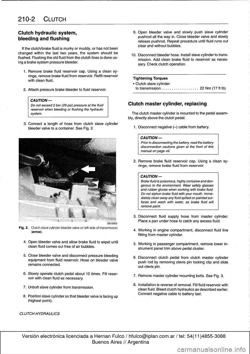
3
.
Connect
a
length
of
hose
from
clutch
slave
cylinder
bleeder
valve
lo
a
container
.
See
Fig
.
2
.
0012003
Fig
.
2
.
Clutch
slave
cylinder
bleeder
valve
on
left
side
of
transmission
(arrow)
.
4
.
Open
bleeder
valve
and
allow
brake
fluid
to
expel
until
clean
fluid
comes
out
free
of
air
bubbles
.
5
.
Close
bleeder
valve
and
disconnect
pressure
bleeding
equipment
from
fluid
reservoir
.
Hose
on
bleeder
valve
remainsconnected
.
6
.
Slowly
operate
clutch
pedal
about10
times
.
Fill
reser-
voir
with
clean
fluid
asnecessary
.
7
.
Unbolt
slavecylinder
from
transmission
.
8
.
Position
slave
cylinder
so
that
bleeder
valve
is
facing
up
(highest
point)
.
CLUTCH
HYDRAULICS
9
.
Open
bleeder
valve
and
slowly
push
slave
cylinder
pushrod
al¡
the
way
in
.
Close
bleeder
valve
and
slowly
release
pushrod
.
Repeat
procedure
until
fluid
runs
out
clear
and
without
bubbles
.
10
.
Disconnect
bleeder
hose
.
Instan
slavecylinder
lo
trans-
mission
.
Add
cleanbrake
fluid
to
reservoir
as
neces-
sary
.
Check
clutch
operation
.
Tightening
Torques
"
Clutch
slave
cylinder
to
transmission
................
..
22
Nm
(17
ft
lb)
Clutch
master
cylinder,
replacing
The
clutch
master
cylinder
is
mounted
to
the
pedal
assem-
bly,
directly
above
the
clutch
pedal
.
1
.
Disconnect
negative
(-)
cable
from
battery
.
CAUTION-
Prior
to
disconnectiog
the
battery,
read
the
battery
disconnection
cautionsgiven
at
the
front
of
this
manual
on
page
viii
.
2
.
Remove
brake
fluid
reservoir
cap
.
Usinga
clean
sy-
ringe,
remove
brake
fluid
from
reservoir
.
CA
UTION-
Brake
fluid
is
poisonous,
highly
corrosive
and
dan-gerous
to
the
environment
.
Wear
safety
glasses
and
rubbergloves
when
working
with
brake
fluid
.
Do
notsiphonbrake
fluid
with
your
mouth
.
Imme-
diately
clean
away
any
fluid
spilled
on
painted
sur-
faces
and
wash
with
water,
asbrake
fluid
will
remove
point
.
3
.
Disconnect
fluid
supply
hose
from
master
cylinder
.
Placea
pan
under
hose
to
catch
any
excess
fluid
.
4
.
Working
in
engine
compartment,
disconnect
fluid
line
fitting
frommaster
cylinder
.
5
.
Working
in
passenger
compartment,
remove
lower
in-
strument
panel
trim
above
pedal
cluster
.
6
.
Disconnect
clutch
pedal
from
clutch
master
cylinder
push
rod
by
removing
clevis
pin
locking
clip
and
slide
out
clevis
pin
.
7
.
Remove
master
cylinder
mounting
bolts
.
See
Fig
.
3
.
8
.
Installation
is
reverse
of
removal
.
Fill
fluid
reservoir
with
clean
fluid
.
Bleed
clutch
hydraulics
as
described
earlier
.
Connect
negative
cable
to
battery
last
.
Page 345 of 759
GENERAL
This
repair
group
covers
interior
trim
removal
and
installa-
tion
procedures
.
Forremoval
and
installation
of
interior
switches,
including
interior
lighting
equipment,
see
612
Switches
and
Electrical
Accessories
.
Most
of
the
interior
trim
and
finish
paneis
are
clipped
or
screwed
into
place
.
Many
of
the
trim
retaining
clips
arede-
signed
to
be
used
only
once
.
When
removing
trim
that
is
held
in
place
with
clips,
it
is
a
good
idea
lo
have
spareson
hand
be-
fore
beginningthejob
.
CENTER
CONSOLE
The
front
section
center
console
houses
the
Multi-Informa-
tion
Display
(MID)
module,the
front
ashtray
and
cigarette
lighter
;
shifter
lever,
power
window
switches
and
the
hazard
warning
switch
.
The
rear
center
console
section
houses
the
ashtray(s)
and
covers
the
emergency
brakecable
ends
.
Center
console,
removing
and
installing
1
.
Disconnect
negative
(-)
cable
from
battery
and
cover
terminal
with
insulating
material
.
CA
UTION-
Prior
to
disconnectiog
the
battery,
read
the
battery
disconnection
cautionsgiven
at
the
front
of
this
manual
onpage
viii
.
2
.
Remove
shifter
boot
or
selectorlever
cover
.
See250
Gearshift
t-inkage
.
3
.
Remove
rear
ashtray
retaining
screws
totake
out
ash-
tray
.
Remove
rear
console
retaining
screwunder
ash-
tray
.
513
Interior
Tri
m
INTERIORTRIM
513-1
GENERAL
..
.
.....
.
.
.
.
.
.
.
.
.
.
.
......
.
.
.
513-1
DASHBOARD
.....
.
.
.
.
.
.
.
.
.
.
.
.
.
.
...
.
:
.
.513-2
Glove
compartment,removing
and
installing
.
.513-2
CENTER
CONSOLE
.
.
.
.
.
.
.
.
.
.
.........
513-1
Lower
left
dash
panel,
Center
console,
removing
and
installing
.....
513-1
removing
and
installing
.
.
.
.
.
.
.
.
.
.
.....
.
.
513-2
Dashboard,removing
and
installing
.
.
.
.
...
.
.513-3
4
.
Remove
Multi-Information
Display
module
.
See620
In-
struments
.
5
.
Remove
hazardwarning
switch
and
power
window
switches
bypushing
up
and
out
from
below
.
6
.
Remove
lower
left
dashboard
panel
and
glove
compart-
ment
as
described
later
in
this
repair
group
.
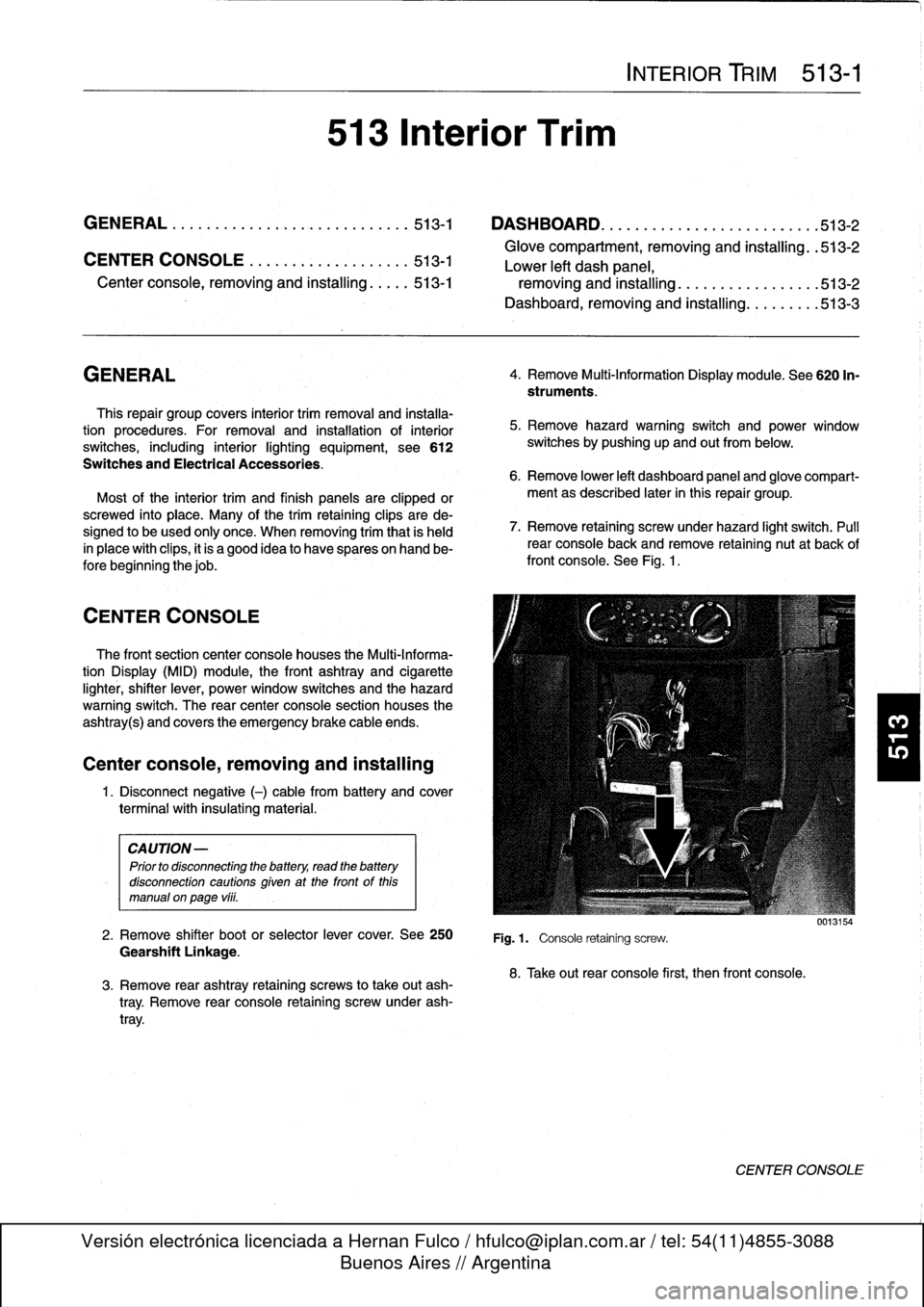
7
.
Remove
retaining
screwunder
hazard
light
switch
.
Pull
rear
console
back
and
remove
retaining
nut
at
back
of
front
console
.
See
Fig
.
1
.
Fig
.1.
Console
retaining
screw
.
8
.
Take
out
rear
console
first,
then
front
console
.
0013154
CENTER
CONSOLE
Page 346 of 759
513-2
INTERIOR
TRim
DASHBOARD
Dashboard
removal
is
a
complex
operation,
involving
dis-
connection
and
dismantling
of
a
number
of
electrical
and
dash
structural
components
.
The
BMW
E36
is
equipped
with
SRS
airbags
mounted
in
the
steering
wheel,
in
the
dashboard
(1994
and
later)
on
the
passenger
side,
and
in
the
front
doors(1997
and
later)
.
Air-
bags
units
are
pyrotechnic
devices
and
should
be
treated
with
extreme
caution
.
Improper
handling
of
the
airbags
could
cause
serious
injury
.
WARNING
-
"
The
BMW
Supplemental
Restraint
System
(SRS)
is
complex
and
special
precautions
must
be
ob-
served
when
servicing
.
Serious
injury
may
result
if
system
service
is
attempted
by
persons
unfa-
miliar
with
the
BMW
SRS
and
its
approved
ser-vice
procedures
.
BMW
specifies
that
all
inspection
and
service
shouldbe
performed
byan
authorized
BMW
dealer
.
"
Beforeperforming
any
work
involving
the
steering
wheel
or
interior
trim
in
the
vicinity
of
the
airbags,
disconnect
the
negative
()
battery
cable
.
See
721
Airbag
System
(SRS)
.
"
SRS
contains
aback-up
power
supply
within
the
SRS
control
module
.
A
10
minute
díscharge
peri-
od
should
be
allowed
after
the
battery
cable
has
been
disconnected
.
Glove
compartment,
removing
and
installing
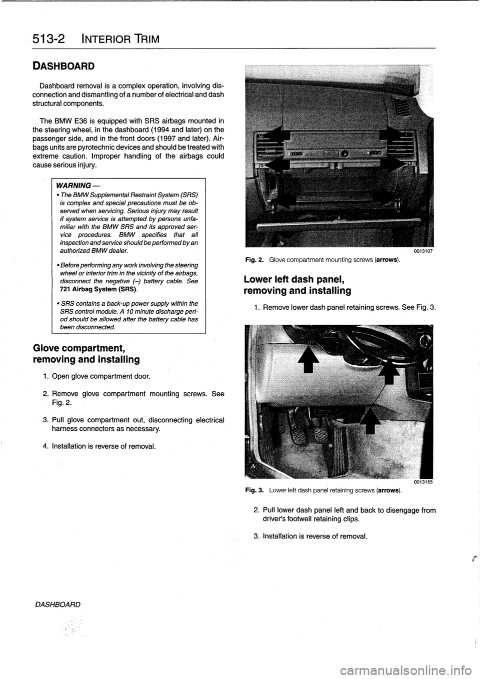
1.
Open
glove
compartment
door
.
2
.
Remove
glove
compartment
mounting
screws
.
See
Fig
.
2
.
3
.
Pull
glove
compartment
out,
disconnecting
electrical
harness
connectors
as
necessary
.
4
.
Installation
is
reverse
of
removal
.
DASH80ARD
Fig
.
2
.
Glove
compartment
mounting
screws
(arrows)
.
Lower
left
dash
panel,
removing
and
installing
0013107
1
.
Remove
lower
dash
panel
retaining
screws
.
See
Fig
.
3
.
0013155
Fig
.
3
.
Lower
left
dash
panel
retaining
screws
(arrows)
.
2
.
Pull
lower
dash
panel
left
and
back
to
disengagefrom
driver's
footwell
retaining
clips
.
3
.
Installation
is
reverse
of
removal
.
Page 347 of 759
Dashboard,
removing
and
installing
1
.
Disconnect
negative
(-)
cable
from
battery
and
cover
terminal
with
insulating
material
.
CAUTION-
Prior
to
disconnectiog
the
battery,
read
the
battery
disconnection
cautionsgiven
at
the
front
of
this
manual
onpage
vi¡¡
.
2
.
Remove
center
console
as
described
earlier
.
3
.
Remove
glove
compartment
as
described
earlier
.
4
.
Remove
lower
left
dash
trim
piece
as
described
above
.
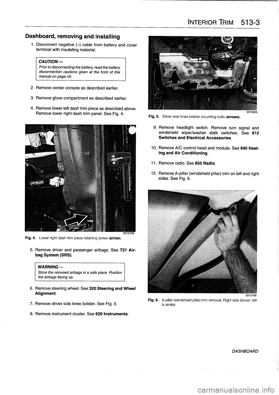
Remove
lower
right
dash
trim
panel
.
See
Fig
.
4
.
Fig
.
4
.
Lower
right
dash
trim
piece
retaining
screw
(arrow)
.
WARNING
-
Store
the
removed
airbags
in
a
safe
place
.
Position
the
airbags
facing
up
.
8
.
Remove
instrument
cluster
.
See
620
Instruments
.
5
.
Remove
driver
and
passenger
airbags
.
See
721
Air-
bag
System
(SRS)
.
6
.
Remove
steering
wheel
.
See
320
Steering
and
Wheel
Alignment
.
INTERIOR
TRIM
513-
3
Fig
.
5
.
Driver
side
knee
bolster
mounting
bolts
(arrows)
.
9
.
Remove
headlight
switch
.
Remove
turn
signal
and
windshield
wiper/washer
stalk
switches
.
See612
Switches
and
Electrical
Accessories
.
10
.
Remove
A/C
control
head
and
module
.
See
640
Heat-ing
and
Air
Conditioning
.
11
.
Remove
radio
.
See650
Radio
.
12
.
Remove
A-pillar
(windshield
pillar)
trim
on
left
and
right
sides
.
See
Fig
.
6
.
UU13156
Fig
.
6
.
A-pillar
(windshield
pillar)
trim
removal
.
Right
side
shown,
left
7
.
Remove
driver
side
knee
bolster
.
See
Fig
.
5
.
is
similar
.
DASHBOARD