wire BMW 318i 1997 E36 Workshop Manual
[x] Cancel search | Manufacturer: BMW, Model Year: 1997, Model line: 318i, Model: BMW 318i 1997 E36Pages: 759
Page 7 of 759
Please
read
these
warnings
and
cautions
before
proceeding
with
maintenance
and
repair
work
.
WARNING-
"
Friction
materials
(such
as
brake
pads
or
shorts
or
clutchdiscs)
contain
asbestos
fibers
or
other
friction
materials
.
Do
notcreate
"
See
also
Cautionson
page
viü
dustby
grinding,
sanding,
orby
cleaning
with
compressed
air
.
"
Some
repairs
may
be
beyond
your
capability
.
If
you
lack
the
Avoid
breathing
dust
.
Breathing
any
friction
material
dust
can
lead
skills,
tools
and
equipment,
or
a
suitable
workplace
for
any
proce-
to
serious
diseases
and
may
result
in
death
.
duredescribed
in
this
manual,
we
suggestyou
leave
such
repairs
"
Batteries
give
off
explosive
hydrogen
gas
during
charging
.
to
an
authorized
BMW
dealer
service
department
or
other
quali-
Keep
sparks,
lighted
matches
and
open
flame
away
from
the
top
fied
shop
.
of
the
battery
If
hydrogen
gas
escaping
from
the
cap
vents
is
"Do
not
re-use
any
fasteners
that
are
worn
or
deformed
in
normal
ignited,
it
will
ignite
gas
trapped
in
the
cells
and
cause
the
battery
use
.
Many
fasteners
are
designed
to
be
used
only
once
and
to
explode
.
become
unreliable
and
may
fail
when
used
a
second
time
.
This
"
Connect
and
disconnect
battery
cables,
jumper
cablesora
bat-
includes,
but
is
not
limited
to,
nuts,
bolts,
washers,
self-locking
nuts
or
bolts,
circlips
and
cotterpins
.
Always
replace
these
fasteners
with
new
parts
.
"Do
not
quick-charge
the
battery
(for
boost
starting)
for
longer
"
Never
work
under
a
lifted
car
unless
it
is
solidly
supportedon
than
one
minute
.
Wait
at
least
one
minute
before
boosting
the
bat-
stands
designed
for
the
purpose
.
Do
not
support
a
car
on
cinder
tery
a
second
time
.
blocks,
hollow
tiles
or
other
props
that
may
crumble
under
contin-
uous
load
.
Never
work
under
acar
that
is
supported
solely
by
a
"Do
not
allow
battery
charging
voltage
to
exceed
16
.5
volts
.
If
the
jack
.
Never
work
under
thecar
while
the
engine
is
running
.
battery
beginsproducing
gas
or
boiling
violently,
reduce
the
charg-
ing
rate
.
Boosting
a
sulfated
battery
at
a
high
charging
rate
can
"
If
you
are
going
to
work
under
acar
on
the
ground,
make
sure
cause
an
explosion
.
that
the
ground
is
level
.
Block
the
wheels
to
keep
the
carfrom
roll-
ing
.
Disconnect
the
battery
negative
(-)
terminal
(ground
strap)to
"
The
air-conditioning
system
is
filled
with
chemical
refrigerant,
prevent
others
from
starting
thecar
while
youare
under
it
.
which
is
hazardous
.
TheA/C
system
should
be
servicedonly
by
trained
technicians
using
approved
refrigerant
recovery/recycling
"
Never
run
the
engine
unless
the
work
area
is
well
ventilated
.
equipment,
trained
in
related
safetyprecautions,
and
familiar
with
Carbon
monoxide
kills
.
regulations
governing
the
discharging
and
disposal
of
automotive
"
Finger
rings,
bracelets
and
other
jewelry
shouldbe
removed
so
chemical
refrigerants
.
tery
charger
only
with
the
ignition
switched
off,
to
prevent
sparks
.
Do
not
disconnect
the
battery
while
the
engine
is
running
.
that
theycannot
cause
electrical
shorts,
get
caught
in
running
"
Do
not
expose
any
partof
the
A/Csystem
to
high
temperatures
machinery,
or
be
crushed
by
heavy
parts
.
suchas
open
flame
.
Excessiveheat
will
increase
system
pressure
"
Tie
long
hair
behind
your
head
.
Do
not
wear
a
necktie,
a
scarf,
and
may
cause
the
system
to
burst
.
loose
clothing,
or
a
necklace
when
you
work
near
machine
tools
or
"
Some
aerosol
tire
inflators
are
highly
flammable
.
Be
extremely
running
engines
.
If
your
hair,
clothing,
or
jewelry
were
to
get
caught
cautious
when
repairing
a
tire
that
may
havebeen
inflated
using
in
the
machinery,
severe
injury
could
result
.
an
aerosol
tire
inflator
.
Keep
sparks,
open
flame
or
other
sources
"
Do
not
attempt
to
work
onyourcar
if
you
do
not
feel
well
.
You
of
ignition
away
from
the
tire
repair
area
.
Inflate
and
deflate
the
tire
increase
the
danger
of
injury
toyourself
and
others
if
you
are
tired,
at
least
four
times
before
breaking
the
bead
from
therim
.
Com-
upset
or
have
takenmedication
or
any
other
substance
that
may
Pletely
remove
the
tire
from
the
rim
beforeattempting
any
repair
.
keep
you
from
being
fully
alert
.
"
Illuminate
your
work
areaadequately
but
safety
.
Use
a
portable
safety
light
for
working
inside
or
under
thecar
.
Make
surethe
bulb
is
enclosedbya
wire
cage
.
The
hot
filament
of
an
accidentally
bro-
ken
bulb
can
ignite
spilled
fuel
or
oil
.
"
Catch
draining
fuel,
oil,
orbrake
fluid
in
suitable
containers
.
Do
not
use
food
or
beverage
containers
that
mightmislead
someone
into
drínking
from
them
.
Store
flammable
fluids
away
from
fire
haz-
ards
.
Wipe
up
spills
at
once,
but
do
not
store
the
oily
rags,
which
can
ignite
and
burn
spontaneously
.
"
Always
observe
good
workshop
practices
.
Wear
goggles
when
youoperate
machine
tools
or
work
with
battery
acid
.
Gloves
or
other
protectioeclothing
should
be
worn
whenever
thejob
requires
working
with
harmful
substances
.
"
Greases,
lubricants
and
other
automotive
chemicals
contain
toxic
substances,
many
of
which
are
absorbed
directly
through
the
skin
.
Read
the
manufacturer's
instructions
and
warnings
carefully
.
Use
hand
andeye
protection
.
Avoid
direct
skin
contact
"
Cars
covered
by
this
manual
are
equipped
with
a
supplemental
restraint
system
(SRS),
that
automatically
deploys
an
airbag(s)
in
theevent
of
a
frontal
ímpact
.
The
airbag(s)
is
inflated
byan
explo-
sive
device
.
Handled
improperly
or
without
adequate
safeguards,
can
be
accidently
activated
and
cause
serious
injury
.
"
The
ignition
system
produces
high
voltages
that
can
be
fatal
.
Avoid
contact
with
exposed
terminals
and
use
extreme
care
when
working
ona
car
with
the
engine
running
or
the
ígnition
switched
on
.
"
Place
jack
stands
only
at
locations
specified
bymanufacturer
.
The
vehicle
lifting
jacksupplied
with
the
vehicle
is
intended
for
tire
changes
only
.
A
heavy
duty
floor
jack
shouldbe
used
to
lift
vehicle
before
installing
jack
stands
.
See
010
Fundamentals
for
theDo-
.
it-Yourself
Owner
.
"
Battery
acid
(electrolyte)
can
cause
severeburns
.
Flush
contact
area
with
water,
seek
medical
attention
.
"
Aerosolcleaners
and
solvents
may
contain
hazardous
ordeadly
vapors
and
are
highly
flammable
.
Use
only
in
a
wellventilated
area
.
Do
not
use
on
hot
surfaces
(engines,
brakes,
etc
.)
.
"
Disconnect
the
battery
negative
(-)
terminal
(Ground
strap)
"
Do
not
remove
coolant
reservoir
or
radiator
cap
with
theengine
whenever
you
work
on
the
fuel
system
orthe
electrical
system
.
Do
hot
.
Danger
of
bums
and
engine
damage
.
not
smoke
or
work
near
heaters
or
other
fire
hazards
.
Keep
an
approved
fire
extinguisher
handy
.
continued
on
next
page
vii
Page 9 of 759
GENERAL
FUNDAMENTALS
FORTHE
DO-IT
YOURSELF
OWNER
010-1
010
Fundamentals
for
the
Do-lt-Yourself
Owner
GENERAL
.......
.
.
.
......
.
.........
.
.
.010-1
TOOLS
.
.
...
.
............
.
............
010-8
Basic
Tool
Requirements
......
.
.
.
.
.
.
.
.
.
.
010-8
HOW
TO
USE
THIS
MANUAL
.
...
.
...
.
.
.
010-2
JackStands
.
.
.
.
.
.
.
.
.
.......
.
.
.
.
...
.
.
010-9
Warnings,
Cautions
and
Notes
.........
.
.
.
010-2
Oil
Change
Equipment
.
....
.
......
.
...
.
.
010-9
GETTING
STARTED
.
.......
.
.
.
.
.
......
.010-2
Torque
Wrench
....
.
.
.
....
.
..
.
.
.
.
.
...
.
010-10
Feeler
Gauges
.
...
.
.
.
.......
.
.
.
.
.
.
.
.
.
010-10
Safety
....
.
.....
.....
.
.
.
.
.
...
.
.
.
.
.
.
.
010-2
Digital
Multimeter
.
.
.
.
.
.....
.
.
.
.
.
.
.
.
.
.
.
010-10
Lífting
the
Car
...........
.
.
.
.
.
.
.
.
.
...
.
.
.
010-3
gMW
Special
Tools
...
.
....
..
.....
.
...
.
010-11
Raising
car
safely
...
..
...
.
...
.
.....
.
...
010-3
Working
under
car
safely
...
..
....
.
.....
.
...
010-4
EMERGENCIES
.
.
.
.
.
.
.....
.
.
.
.
.
.
.
...
.
010-11
ADVICE
FOR
THE
BEGINNER
.......
.
.
.
010-4
Changing
a
Tire
.
.
.
.
.
.
....
..
.
.
.
.
.
.
.
.
.
.010-11
Car
Will
Not
Start
....
.
....
.
.
.
........
.010-11
Planning
Ahead
....
.
...........
.
....
.
.
.
010-4
Jump
Starting
Car
..
.
.
.
....
.
...........
010-12
Cleanliness
.
.
.
.
.
.
.
..
....
.
.
.
.
.
.
.
.
.
.
.
.
.
.
.
010-4
Overheating
.
.....
.
.
.
.........
.
.
.
...
.
010-12
Non-reusable
Fasteners
...
.
.
.
.
.
.
.
.
.
.
.
.
.
.
.
010-5
Low
Oil
Pressure
...
...
.
.
...
.
.
.
..
...
....
010-13
Tightening
Fasteners
.....
.
.
.
...
.
.
.
.
.
.
.
.
.
010-5
Brake
Fluid
Level
.
.
.....
.
.
.
.
.
...
.
.....
010-13
Gaskets
and
Seals
.......
.
.
.
...
.
.....
.
.
.
010-5
Check
Engine
Warning
Light
.
.
.
...
.
.....
010-13
Electrical
Testing
.
.
.
.
.
.
.
.
.
.
.
.
.
.
.
.
.
...
.
.
.
010-6
pim
Lights
.....
.
..
.
.
.
....
.
.
.
.........
010-13Wire
Repairs
.
.
.
.
.
.
.
.
.
.
...
.
.
.
.
.
.
.
......
010-6
Towíng
.
.
...
.
.
.
.
.
.
.
.
.
.
.
...
.
.
.
.
.
...
.
.010-13
BUYINGPARTS
.
.
.
.....
.
.
.
...
.
.
.
...
.
.
.
010-6
Spare
Parts
Kit
.
.
.
.
.
.
.......
.
.
.
.
.
.....
010-14
Genuine
BMW
Parts
.
.
.
.
.
.
.
.
.
.
.
.
.
.
......
010-6
Non-returnable
Parts
.
.
.
.
.
.
.
.
.
.
.
.
.
.
......
010-7
TABLES
Information
You
Need
to
Know
.
.
.
.
.
.
......
010-7
a
.
General
Bolt
Tightening
Torques
SERVICE
.
.
.
.
.
.
.
.
.
.
.
.
.......
.
..........
010-7
Although
the
BMW
is
a
sophisticated
and
complex
machine,
basic
maintenance
can
be
accomplished
byan
interested
own-
er
with
mechanical
skills
and
the
right
information
.
Most
of
the
preventive
maintenance
that
is
required
in
the
lifetime
of
theav-
erage
BMW
is
weil
within
the
capabilitiesof
the
do-it-yourseifer
.
WARNING
-
Do
not
use
this
manual
unless
you
are
familiar
with
basicautomotive
repair
procedures
and
sale
work-
shop
practices
.
This
manual
illustrates
the
work-
shop
procedures
required
for
most
service
work
;it
is
not
a
substitute
for
full
and
up-to-date
information
from
the
vehicle
manufacturer
or
for
proper
training
asan
automotive
technician
.
Note
that
it
is
not
pos-
sible
for
us
to
anticipate
al¡
of
the
ways
orconditions
underwhich
vehicles
may
be
serviced
or
to
provide
cautions
as
to
all
of
the
possible
hazards
that
may
result
'
in
Nm
(max
.
permissible)
.
..
.
...
............
.
010-5
WARNING
-
Your
common
sense
and
good
judgment
are
crucial
tosale
and
successful
service
work
.
Read
proce-
dures
through
before
starting
them
.
Thinkabout
whether
the
condition
ofyour
car,
your
leve¡
of
me-
chanical
skill,
or
your
leve¡
of
reading
comprehen-
sion
might
result
in
orcontribute
in
some
way
to
an
occurrence
that
might
cause
you
injury
damage
your
car,
or
result
in
an
unsafe
repair
.
lf
you
havedoubts
for
these
or
other
reasonsaboutyour
abilíty
to
perform
sale
repair
work
onyour
car,
have
the
work
done
at
an
authorized
BMW
dealer
or
other
qualified
shop
.
This
section
of
the
manual
is
intended
to
helpthe
beginner
get
started
.
To
begin
with
there
is
a
discussion
on
How
To
Use
This
Manual
.
Tips
on
mechanicas
skills
and
workshop
practic-
es
that
can
help
the
beginner
do
a
faster
and
more
thorough
job
can
be
foundunderGettingStarted
.
The
basic
tools
needed
to
do
most
of
the
procedures
in
this
manual
are
foundunder
Tools
.
The
section
ends
with
a
quick
reference
guide
to
Emer-
gencies,
including
basictroubleshooting
and
information
on
how
to
gauge
the
seriousness
of
a
problem
.
GENERAL
Page 14 of 759
010-
6
FUNDAMENTALS
FOR
THE
DO-ITYOURSELF
OWNER
In
places
where
a
shaft
mustpass
through
a
housing,
flexible
lip
seals
areused
to
keep
the
lubricating
oil
or
grease
from
leak-
ingout
past
the
rotating
shaft
.
Seals
should
never
be
reused
once
they
have
been
removed
.
When
removing
a
seal,
be
care-
ful
not
lo
scratch
or
otherwise
damage
the
metal
surfaces
.
Even
minor
damage
to
sealing
surfaces
can
cause
sea¡
damage
and
leakage
.
The
key
to
sea¡
installation
is
to
get
the
sea¡
in
straight
without
damaging
¡t
.
Use
a
sea¡
driver
that
is
the
same
diameter
as
the
seal
housing
to
gently
and
evenly
insta¡I
into
place
.
If
a
proper
size
seal
driver
is
not
available,
a
socket
of
the
right
size
will
do
.
When
installing
a
seal,
¡t
a
good
idea
to
coat
the
sea¡
with
o¡I
to
aid
installation
.
Some
seals
are
directional
and
special
instal-
lation
instructions
apply
.
Make
sure
¡t
is
installed
with
the
lip
fac-
ing
the
correct
way
.
Normally
the
lip
faces
the
inside
.
Note
the
installation
direction
of
the
old
sea¡before
removing
¡t
.
Electrical
Testing
Many
electrical
problems
canbe
understood
and
solved
with
only
a
little
fundamental
knowledge
of
how
electrical
circuits
Insulate
the
finished
connection
.
Electronics
stores
can
sup-
function
.
ply
heat-shrinkable
insulating
tubing
that
can
be
placed
onto
the
wire
before
connectiog,
slid
over
the
finished
joint,
and
Electric
current
only
flows
in
a
complete
circuit
.
To
operate,
shrunk
to
a
tight
fit
with
a
heat
gun
orhair
dryer
.
The
nextbest
every
electrical
device
in
thecar
requires
a
complete
circuit
in-
alternative
is
electrical
tape
.
Make
sure
the
wire
is
clean
and
cluding
a
voltage
source
and
a
pathto
ground
.
The
positive
(+)
free
ofsolder
flux
or
other
contamination
.
Wrap
the
joint
tightly
side
of
the
battery
is
the
original
voltagesource,
and
ground
is
to
sea¡
out
moisture
.
See
600
Electrical-General
for
more
in-
any
retum
path
to
the
negative
()
-
side
ofth
e
battery°
whether
li
formation
.
through
the
wiring
harness
or
thecar
body
.
Except
for
portions
of
the
charging
system,
al¡
electrical
current
in
the
car
is
direct
current
(DC)
and
flows
from
positive
(+)
to
negative
(-)
.
BVYING
PART$
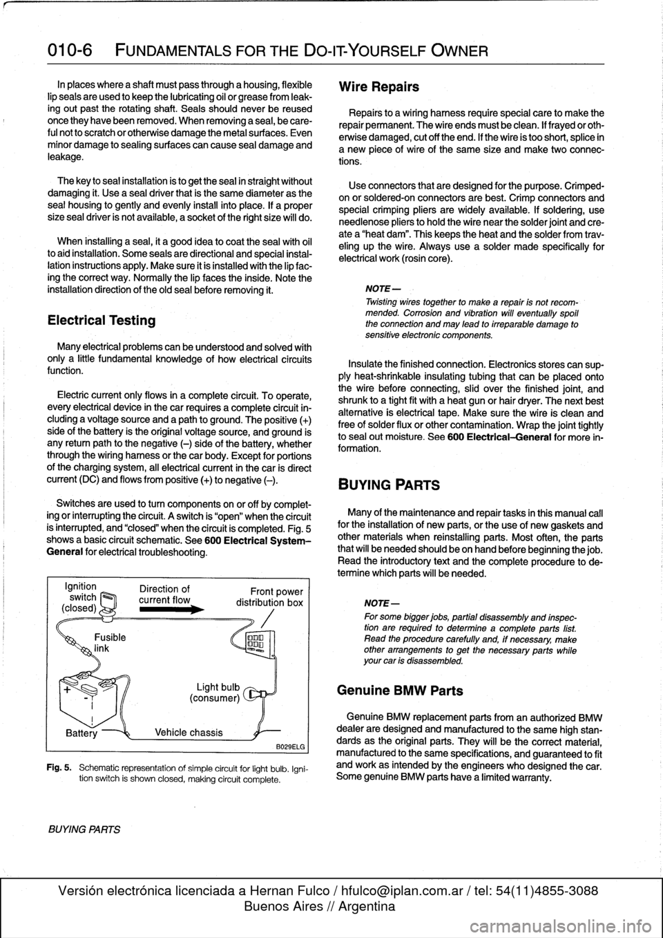
Switches
are
used
to
turn
components
on
or
off
by
complet-
ing
or
interrupting
#he
circuit
.
A
switch
is
"open"
when
the
circuit
Many
of
the
maíntenance
and
repair
tasks
in
this
manual
cal¡
is
ínterrupted,
and
"closed"
when
the
circuit
is
completed
.
Fig
.
5
for
the
installation
of
new
parte,
or
the
use
of
new
gaskets
and
shows
a
basic
circuit
schematic
.
See600
Electrical
System-
other
materials
when
reinstalling
parts
.
Most
often,
the
parts
General
for
electrical
troubleshooting
.
that
will
be
needed
should
be
on
hand
beforebeginningthe
job
.
Read
the
introductory
text
and
the
complete
procedure
to
de-
termine
which
parts
will
be
needed
.
B029ELG
Fig
.
5
.
Schematic
representation
of
simple
circuit
for
light
bulb
.
Igni-
tion
switch
is
shown
closed,
making
circuit
complete
.
BVYING
PARTS
Wire
Repairs
Repairs
to
a
wiring
harness
requirespecial
care
to
make
the
repair
permanent
.
The
wire
endsmust
be
clean
.
lf
frayedor
oth-
erwise
damaged,
cut
off
the
end
.
If
the
wire
is
too
short,
splice
in
a
new
piece
of
wire
of
the
same
size
and
make
two
connec-
tions
.
Use
connectors
that
are
designed
for
the
purpose
.
Crimped-
on
or
soldered-onconnectors
are
best
.
Crimp
connectors
and
special
crimping
pliers
are
widely
available
.
If
soldering,
use
needlenose
pliers
tohold
the
wire
near
the
solder
joint
and
cre-
ate
a
"heat
dam"
.
This
keeps
the
heat
and
the
solder
from
trav-
eling
up
the
wire
.
Always
use
a
solder
made
specifically
for
electrical
work
(rosin
core)
.
NOTE-
Twisting
wirestogether
to
make
a
repair
is
not
recom-
mended
.
Corrosion
and
vibration
will
eventually
spoil
the
connection
and
may
lead
to
irreparable
damage
to
sensitive
electronic
componente
.
NOTE-
For
some
bigger
jobs,
partial
disassembly
and
inspec-
tion
are
required
to
determine
acomplete
parts
list
.
Read
the
procedure
carefully
and,
if
necessary,
make
other
arrangements
to
get
the
necessary
parts
while
your
car
is
disassembled
.
Genuine
BMW
Parts
Genuine
BMW
replacement
parts
from
an
authorized
BMW
dealer
are
designed
and
manufactured
lo
the
same
high
stan-
dards
as
the
original
parts
.
They
will
be
the
correct
material,
manufactured
to
the
same
specifications,
and
guaranteed
lo
fit
and
work
as
intended
by
the
engineers
who
designed
thecar
.
Some
genuine
BMW
parts
have
a
limited
warranty
.
Page 21 of 759
If
steam
is
coming
from
the
engine
compartment
thenthere
is
With
the
engine
and
ignition
off,
check
for
loose
or
corroded
most
likely
a
burst
coolant
hose
or
a
large
leak
in
the
cooling
battery
cables
or
wires
at
the
battery
or
thealtemator
.
Discon-
system
.
To
find
the
leak,
look
for
signs
of
coolant
leakage
on
necting,
cleaning,
and
reinstalling
corroded
wires
and
connec-
hoses,
at
hose
connections,
or
on
the
radiator
.
Let
theengine
tors
may
solve
the
problem
.
Also
check
drive
belt
tension
as
cool
thoroughly,
then
add
coolant
or
water
to
fill
the
system
and
described
in
020
Maintenance
Program
.
start
the
engine
.
If
a
great
deal
of
water
or
coolant
flows
out
of
the
hole,
then
thecarshouldnot
be
driven
until
repairs
are
made
.
lf
there
is
slight
seepage,
then
it
may
be
possible
to
drive
TOWi
ng
a
short
distance,
adding
coolant
as
needed
.
The
cars
covered
by
this
manual
should
be
towed
witha
tow
truck
using
wheel
lift
or
flat
bed
equipment
.
Do
not
tow
thecar
on
all
four
wheels
except
for
very
short
distances
to
move
it
to
a
safe
place
.
If
thered
engine
oil
pressure
warning
light
illuminates,
imme-
diately
stop
thecar
and
turn
off
the
engine
.
Have
the
vehicle
A
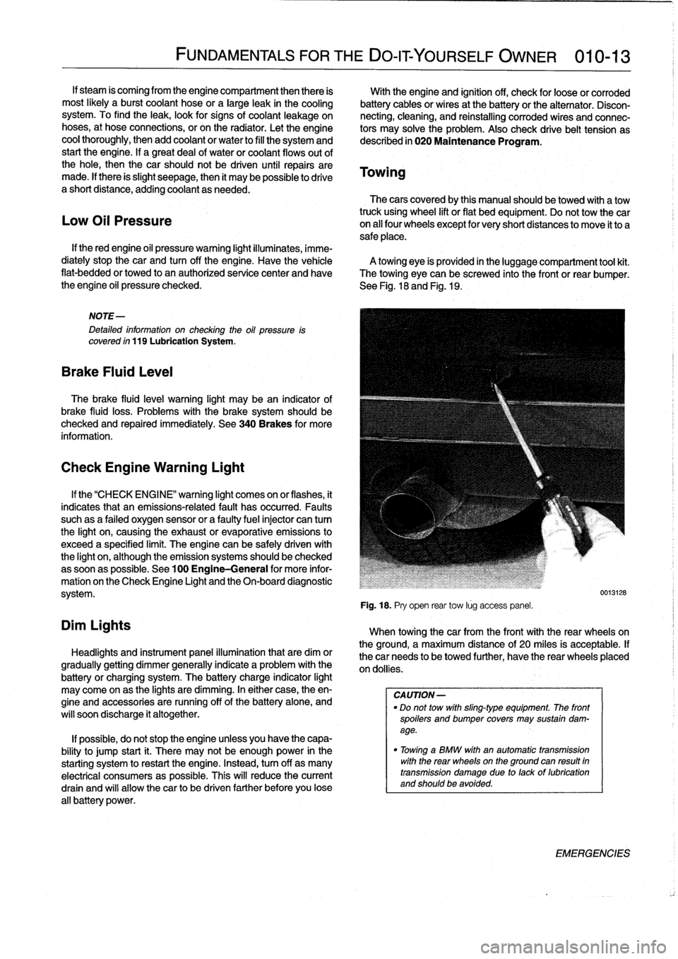
towing
eye
is
provided
in
the
luggage
compartment
tool
kit
.
flat-bedded
or
towed
to
an
authorized
service
center
and
have
The
towing
eye
can
be
screwed
into
the
front
or
rear
bumper
.
the
engine
oil
pressure
checked
.
See
Fig
.
18
and
Fig
.
19
.
Low
Oil
Pressure
NOTE-
Detafed
information
on
checking
the
oil
pressure
is
covered
ín
119
Lubrication
System
.
Brake
Fluid
Leve¡
The
brake
fluid
leve¡
warning
light
may
bean
indicator
of
brake
fluid
loss
.
Problems
with
the
brakesystem
should
be
checked
and
repaired
immediately
.
See
340Brakes
for
more
information
.
Check
Engine
Warning
Light
Dim
Lights
FUNDAMENTALS
FOR
THE
DO-IT
YOURSELF
OWNER
010-13
If
the
"CHECK
ENGI
NE"
warning
light
comes
on
or
flashes,
it
indicates
that
an
emissions-related
fault
has
occurred
.
Faults
suchas
a
failed
oxygen
sensor
or
a
faultyfuelinjector
can
tum
the
light
on,
causing
the
exhaust
or
evaporative
emissions
to
exceed
a
specified
limit
.
The
engine
can
be
safely
driven
with
the
light
on,
although
the
emission
systems
should
be
checked
assoonas
possible
.
See
100
Engine-General
for
more
infor-
mation
on
the
Check
Engine
Light
and
the
On-board
diagnostic
system
.
Headlights
and
instrument
panel
illuminationthat
are
dim
or
gradually
getting
dimmer
generally
indicate
a
problem
with
the
battery
or
charging
system
.
The
battery
charge
indicator
light
may
come
on
as
the
lights
are
dimming
.
In
either
case,
theen-
gine
and
accessories
are
running
off
of
the
battery
alone,
and
will
soon
discharge
it
altogether
.
If
possible,
do
not
stop
the
engine
unless
you
have
the
capa-
bility
to
jump
start
¡t
.
There
may
not
be
enough
power
in
the
starting
system
torestart
the
engine
.
Instead,turn
off
as
many
electrical
consumers
as
possible
.
This
will
reduce
the
current
drain
and
will
allow
thecar
to
be
driven
farther
before
you
lose
all
battery
power
.
Fig
.
18
.
Pry
open
rear
tow
lúg
access
panel
.
When
towingthecar
from
the
front
with
the
rear
wheelson
the
ground,
a
maximum
distance
of
20
miles
is
acceptable
.
If
thecar
needs
to
be
towed
further,
have
the
rear
wheels
placed
on
dollies
.
CA
UTION-
"
Do
not
tow
with
sling-type
equipment
The
front
spoilers
andbumper
covers
may
sustain
dam-
age
.
"
Towínga
BMW
with
an
automatic
transmission
with
the
rear
wheelson
the
ground
can
resuft
in
transmission
damage
due
to
lackof
lubrication
and
should
be
avoided
.
0013128
EMERGENCIES
Page 33 of 759
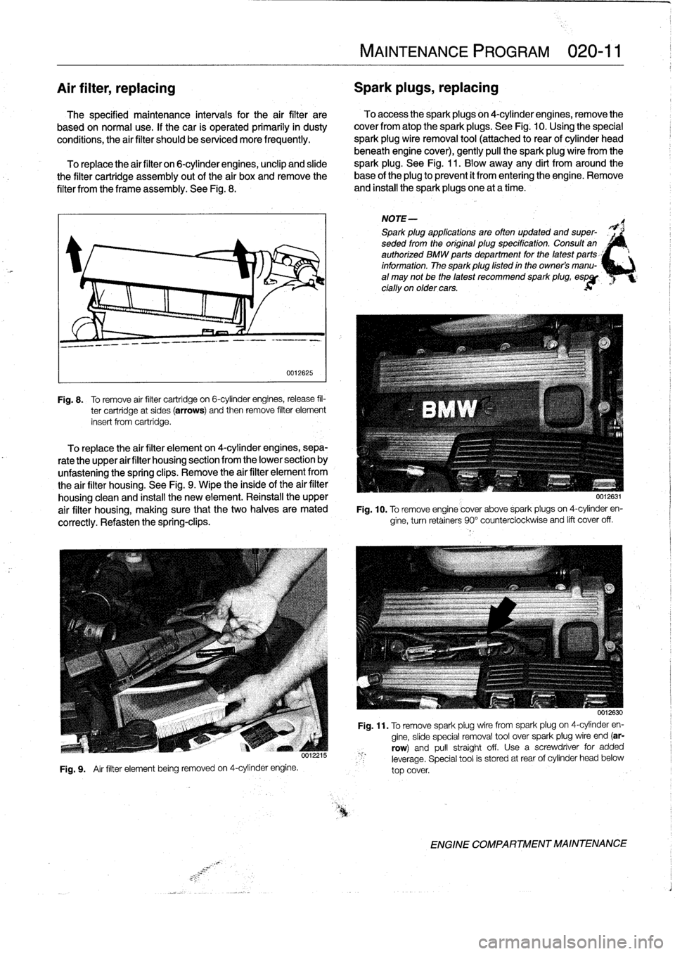
Air
filter,
replacing
Spark
plugs,
replacing
The
specified
maintenance
intervals
for
the
air
filter
are
To
access
the
spark
plugs
on
4-cylinder
engines,
remove
the
based
on
normal
use
.
If
thecar
is
operated
primarily
in
dusty
cover
fromatop
the
sparkplugs
.
See
Fig
.
10
.
Using
the
special
conditions,
the
air
filter
should
be
serviced
more
frequently
.
spark
plug
wire
removal
tool
(attached
to
rear
of
cylinder
head
beneath
engine
cover),
gently
pull
the
spark
plugwire
from
the
To
replace
the
air
filter
on
6-cylinder
engines,
unclip
and
sude
spark
plug
.
See
Fig
.
11
.
Blow
away
any
dirt
from
around
the
the
filter
cartridge
assembly
out
of
the
air
boxand
remove
the
base
of
the
plug
to
prevent
it
from
entering
theengine
.
Remove
filter
from
the
frame
assembly
.
See
Fig
.
8
.
and
install
the
spark
plugs
one
at
a
time
.
0012625
Fig
.
8
.
To
remove
air
filter
cartridge
on
6-cylinder
engines,release
fil-
ter
cartridge
at
sides
(arrows)
and
then
remove
filter
element
insert
from
cartridge
.
To
replace
the
air
filter
elementon
4-cylinder
engines,
sepa-
rate
the
upper
air
filter
housing
section
from
the
lower
section
by
unfastening
the
spring
clips
.
Remove
the
air
filter
element
from
the
air
filter
housing
.
See
Fig
.
9
.
Wipe
the
inside
of
the
air
filter
housing
clean
and
install
the
new
element
.
Reinstall
the
upper
air
filter
housing,
making
sure
that
the
two
halves
are
mated
correctly
.
Refasten
the
spring-clips
.
Fig
.
9
.
Air
filter
element
being
removed
on
4-cylinder
engine
.
MAINTENANCE
PROGRAM
020-
11
NOTE-
Spark
plug
applications
are
often
updated
and
super-
seded
from
the
original
plug
specification
.
Consuff
an
authorized
BMW
parts
department
for
the
latest
parts
_'
information
.
The
sparkplug
fisted
in
the
owners
manu-
al
may
not
be
the
latest
recommend
spark
plug,
espgp
cially
on
older
cars
.
0012631
Fig
.
10
.
To
remove
engine
cover
above
sparkpiugs
on
4-cylinder
en-
gine,
turnretainers
90°
counterclockwise
and
lift
cover
off
.
0012630
Fig
.
11
.
To
remove
spark
plugwirefrom
spark
plug
on
4-cylinder
en-
gine,
sude
special
removal
tool
over
spark
plug
wire
end
(ar-
row)
and
pull
straightoff
.
Usea
screwdriver
for
added
leverage
.
Special
tool
is
stored
at
rear
of
cylinder
head
below
top
cover
.
ENGINE
COMPARTMENT
MAINTENANCE
Page 34 of 759
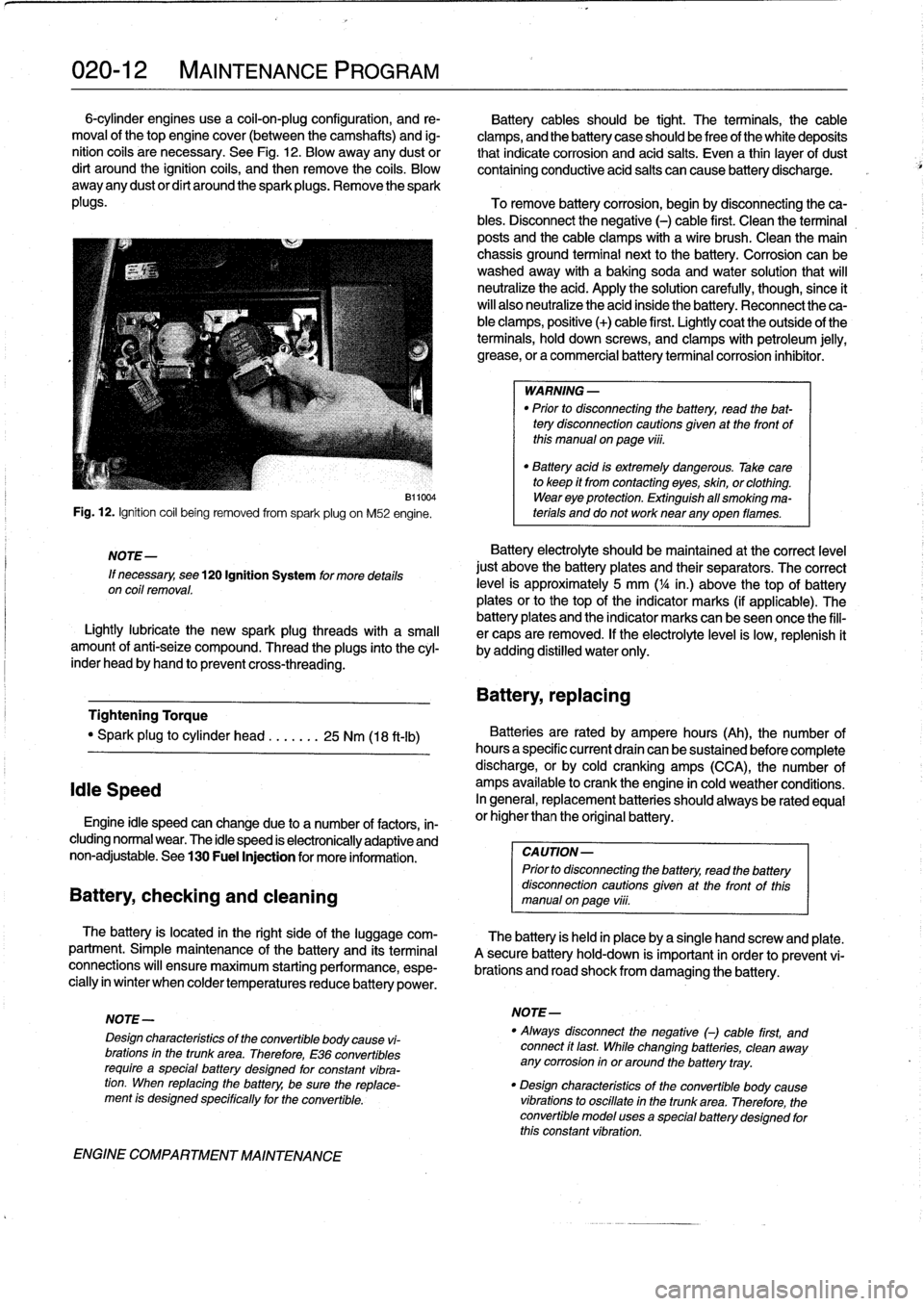
020-
1
2
MAINTENANCE
PROGRAM
6-cylinder
engines
use
a
coil-on-plug
configuration,
and
re-
Battery
cablesshould
be
tight
.
The
terminals,
the
cable
moval
of
thetop
engine
cover
(between
the
camshafts)
and
ig-
clamps,
and
the
battery
case
should
be
freeof
the
white
deposits
nition
cofs
are
necessary
.
See
Fig
.
12
.
Blow
away
any
dust
or
that
indicate
corrosion
and
acid
salts
.
Even
a
thin
¡ayer
of
dust
dirt
around
the
ignition
coils,
and
then
remove
the
coils
.
Blow
containing
conductive
acid
salts
can
cause
battery
discharge
.
away
any
dustor
dirt
around
the
sparkplugs
.
Remove
the
spark
plugs
.
To
remove
battery
corrosion,
begin
by
disconnecting
theca-
bles
.
Disconnect
the
negative
(-)
cable
first
.
Clean
the
terminal
posts
and
the
cable
clamps
with
a
wire
brush
.
Clean
the
main
chassis
ground
terminal
next
to
the
battery
.
Corrosion
can
be
washedaway
with
a
baking
soda
and
water
solution
that
will
neutralize
the
acid
.
Apply
the
solution
carefully,
though,since
ít
will
also
neutralize
the
acid
inside
the
battery
.
Reconnect
the
ca-
ble
clamps,
positive
(+)
cable
first
.
Lightly
coat
the
outside
of
the
terminals,
hold
down
screws,
and
clamps
with
petroleum
jelly,
grease,
or
a
commercial
battery
terminal
corrosion
inhibitor
.
Fig
.
12
.
Ignition
coil
being
removed
from
spark
plug
on
M52
engine
.
NOTE-
If
necessary,
see
120
Ignition
System
for
more
details
on
coil
removal
.
B11004
Lightlylubricate
the
new
spark
plug
threads
with
a
small
amount
of
anti-seize
compound
.
Thread
the
plugs
into
the
cyl-
inder
head
byhand
to
prevent
cross-threading
.
Tightening
Torque
"
Spark
plug
to
cylinder
head
.......
25
Nm
(18
ft-ib)
Idie
Speed
Engine
¡dle
speed
canchange
due
to
a
number
of
factors,
in-
cluding
normal
wear
.
The
idle
speed
is
electronically
adaptive
and
non-adjustable
.
See
130
Fuel
Injection
for
more
information
.
Battery,
checking
and
cleaning
The
battery
is
located
in
the
right
side
of
the
luggage
com-
partment
.
Simple
maintenance
of
the
battery
and
its
terminal
connections
will
ensure
maximum
starting
performance,
espe-
cially
in
winter
when
colder
temperaturesreduce
battery
power
.
ENGINE
COMPARTMENT
MAINTENANCE
WARNING
-
"
Prior
to
disconnecting
the
battery,
read
the
bat-
tery
disconnection
cautions
given
at
the
front
of
this
manualonpage
viii
.
"
Battery
acid
is
extremely
dangerous
.
Take
care
to
keep
it
from
contacting
eyes,
skin,
or
clothing
.
Wear
eye
protection
.
Extinguish
all
smoking
ma-
terials
and
do
not
worknear
any
oyen
flames
.
Battery
electrolyte
should
be
maintained
at
the
correct
level
just
above
the
battery
plates
and
their
separators
.
The
correct
leve¡
is
approximately
5
mm
(
1
/4
in
.)
above
thetop
of
battery
plates
orto
thetop
of
the
indicator
marks
(if
applicable)
.
The
battery
plates
and
the
indicator
marks
can
beseen
once
the
fill-
er
caps
are
removed
.
If
the
electrolyte
level
is
low,
replenish
it
by
adding
distilled
water
only
.
Battery,
repiacing
Batteries
are
rated
by
ampere
hours
(Ah),
the
number
of
hoursa
specific
current
draín
can
be
sustained
before
complete
discharge,
or
by
cold
cranking
amps
(CCA),
the
number
of
amps
available
to
crank
the
engine
in
cold
weather
conditions
.
In
general,
replacement
batteries
should
alwaysbe
rated
equal
or
higherthan
the
original
battery
.
CAUTION-
Prior
to
disconnecting
the
battery,
read
the
battery
disconnection
cautions
given
at
the
front
of
thls
manual
on
page
viii
.
The
battery
is
held
in
place
bya
single
hand
screw
and
píate
.
A
secure
battery
hold-down
is
important
in
order
to
prevent
vi-
brations
and
road
shock
from
damaging
the
battery
.
NOTE-
NOTE-
"
Always
disconnect
the
negative
()
cable
first,
and
Design
characteristics
of
the
convertible
body
cause
vi-
connect
ft
last
While
changing
batteries,
clean
away
brations
in
the
trunk
area
.
Therefore,
E36
convertibles
any
corrosion
in
or
around
the
battery
tray
.
require
a
specialbattery
designed
for
constant
vibra-
tion
.
When
repiacing
the
battery,
be
sure
the
replace-
"
Design
characteristics
of
the
convertible
body
cause
ment
is
designed
specffically
for
the
convertible
.
vibrations
to
oscillate
in
the
trunk
area
.
Therefore,
the
convertible
model
uses
a
specialbattery
designed
for
this
constant
vibration
.
Page 37 of 759
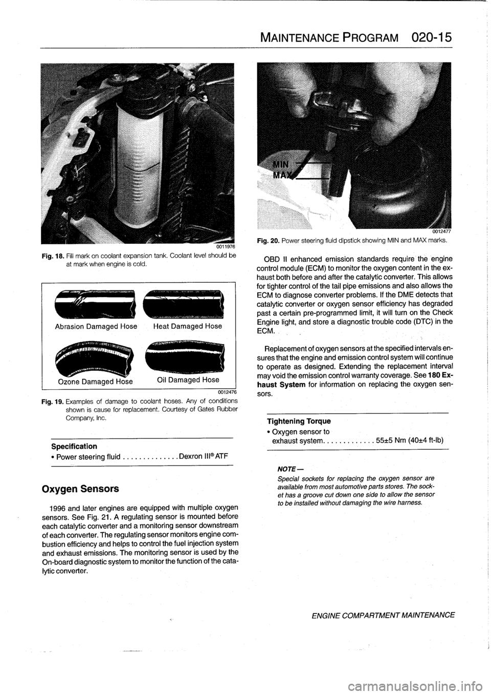
Fig
.
18
.
Fill
mark
on
coolant
expansion
tank
.
Coolant
level
should
be
at
mark
when
engine
ís
cold
.
.
..
e
..
.-
..
~
..
.-
.
Ozone
Damaged
Hose
0012476
Fig
.
19
.
Examples
of
damage
to
coolant
hoses
.
Any
of
conditions
shown
is
cause
for
replacement
.
Courtesy
of
Gates
Rubber
Company,
Inc
.
Specification
"
Power
steering
fluid
..........
.
...
Dexron
III®ATF
Oxygen
Sensors
1996
and
later
engines
are
equipped
withmultiple
oxygen
sensors
.
See
Fig
.
21
.
A
regulating
sensor
is
mounted
before
each
catalytic
converter
and
amonitoring
sensor
downstream
of
each
converter
.
The
regulating
sensor
monitors
engine
com-
bustion
efficiency
and
helps
to
control
the
fuel
injection
system
and
exhaust
emissions
.
The
monitoring
sensor
is
usedby
the
On-board
diagnostic
system
to
monitor
the
function
of
the
cata-
lytic
converter
.
MAINTENANCE
PROGRAM
020-
1
5
NOTE-
5pecialsockets
for
replacingthe
oxygen
sensor
are
available
from
most
automotive
parts
stores
.
The
sock-
et
has
agroove
cut
down
one
side
to
allow
the
sensor
to
be
installed
without
damaging
the
wire
hamess
.
Fig
.
20
.
Power
steering
fluid
dipstick
showing
MIN
and
MAX
marks
.
OBD
II
enhanced
emission
standards
require
the
engine
control
module
(ECM)
to
monitor
the
oxygen
content
in
theex-
haust
bothbefore
and
after
the
catalytic
converter
.
This
allows
for
tightercontrol
of
the
tail
pipe
emissions
and
also
allowsthe
ECM
to
diagnose
converter
problems
.
lf
the
DME
detects
that
catalytic
converter
or
oxygen
sensor
efficiency
has
degraded
past
a
certain
pre-programmed
limit,
it
will
turn
on
the
Check
Engine
light,
and
store
a
diagnostic
trouble
code
(DTC)
in
the
ECM
.
Replacement
of
oxygen
sensors
at
the
specified
intervals
en-
sures
that
the
engine
and
emission
control
system
wíll
continue
to
operate
as
designed
.
Extending
the
replacement
interval
may
void
the
emission
control
warranty
coverage
.
See
180
Ex-
haust
System
for
information
on
replacing
the
oxygen
sen-
sors
.
Tightening
Torque
"
Oxygen
sensor
to
exhaust
system
........
.
.
.
..
55±5
Nm
(40±4
ft-Ib)
ENGINE
COMPARTMENT
MAINTENANCE
Page 47 of 759
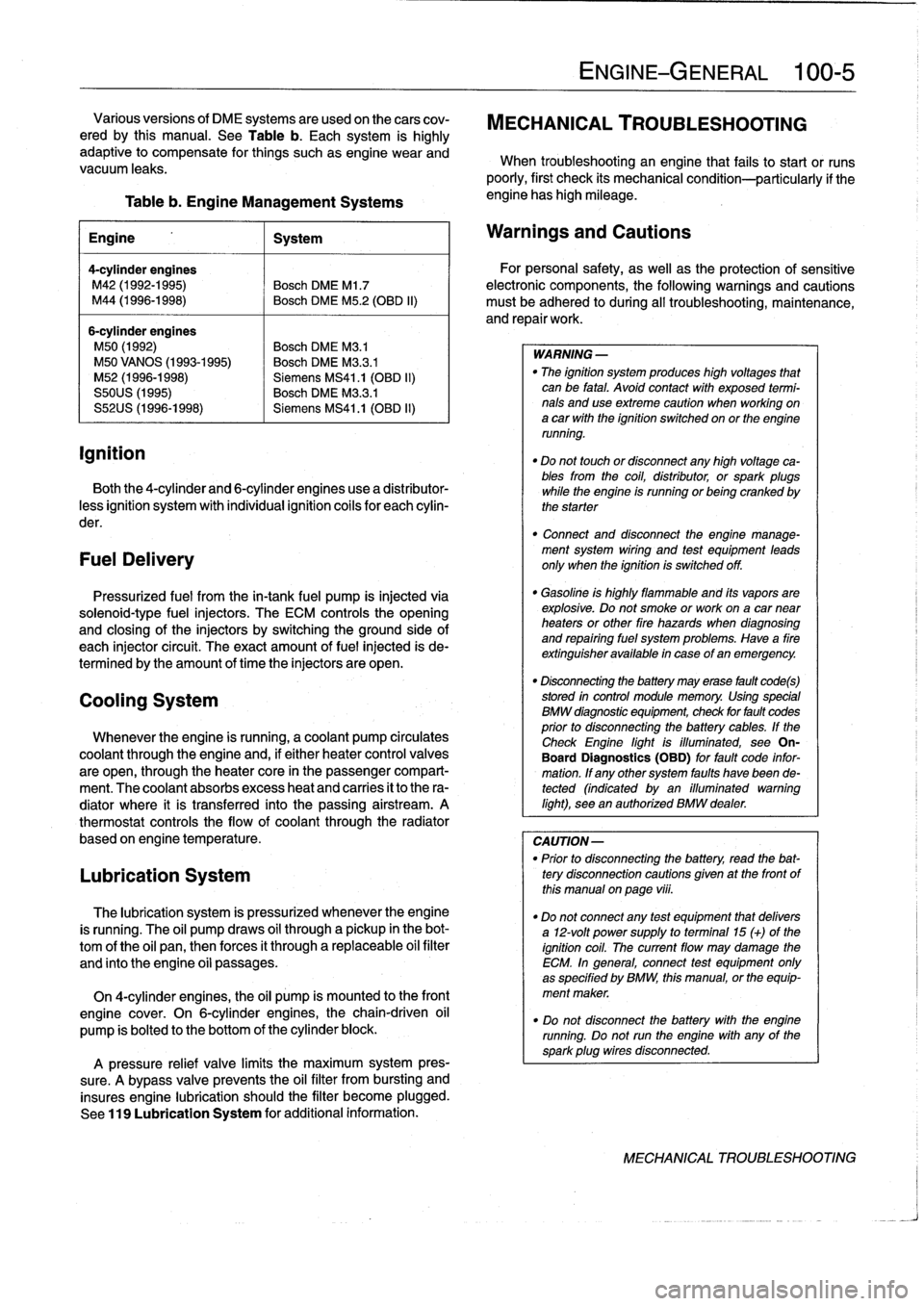
ignition
Table
b
.
Engine
Management
Systems
engine
has
high
mileage
.
Engine
1
System
4-cylinder
engines
M42
(1992-1995)
Bosch
DME
Ml
.7
M44
(1996-1998)
Bosch
DME
M5
.2
(OBD
II)
6-cylinder
engines
M50
(1992)
Bosch
DME
M3
.1
M50
VANOS
(1993-1995)
Bosch
DME
M3
.3
.1
M52
(1996-1998)
Siemens
MS41
.1
(OBD
II)
S50US
(1995)
Bosch
DME
M3
.3
.1
S52US
(1996-1998)
Siemens
MS41
.1
(OBD
II)
Both
the
4-cylinder
and
6-cylinder
engines
use
a
distributor-
less
ignition
system
with
individual
ignition
coils
for
each
cylin-
der
.
FuelDelivery
Pressurized
fuel
from
the
in-tank
fuel
pump
is
injected
via
solenoid-type
fuel
injectors
.
The
ECM
controls
the
opening
and
closing
of
the
injectors
by
switchingthe
ground
side
of
each
injector
circuit
.
The
exact
amount
of
fuel
injected
is
de-
termined
by
the
amount
of
timethe
injectors
are
open
.
Cooling
System
Whenever
the
engine
is
running,
acoolant
pump
circulates
coolant
through
the
engine
and,
if
either
heater
control
valves
are
open,
through
the
heater
core
in
the
passenger
compart-
ment
.
The
coolant
absorbs
excess
heat
and
carries
it
to
the
ra-
diator
where
it
is
transferred
into
the
passing
airstream
.
A
thermostat
controls
the
flow
of
coolant
through
the
radiator
based
on
engine
temperature
.
Lubrication
System
The
lubrication
system
is
pressurized
whenever
theengine
is
running
.
The
oil
pump
draws
oil
through
a
pickup
in
the
bot-
tom
of
the
oil
pan,thenforces
it
through
a
replaceable
oil
filter
and
finto
the
engine
oíi
passages
.
On
4-cylinder
engines,
the
oil
pump
is
mounted
to
the
front
engine
cover
.
On
6-cylinder
engines,thechain-driven
oil
pump
is
bolted
to
the
bottom
of
the
cylinder
block
.
A
pressure
relief
valve
limits
the
maximum
system
pres-
sure
.
A
bypass
valve
prevents
the
oil
filter
from
bursting
and
insures
engine
lubrication
should
the
filter
become
plugged
.
See
119
Lubrication
System
for
additional
information
.
ENGINE-GENERAL
100-
5
Various
versions
of
DME
systems
are
usedon
thecars
cov-
MECHANICAL
TROUBLESHOOTING
ered
by
this
manual
.
See
Table
b
.
Each
system
is
highly
adaptive
to
compensate
for
things
suchasengine
wear
and
When
troubleshooting
an
engine
that
fails
to
start
or
runs
vacuum
leaks
.
poorly,
first
check
its
mechanical
condition-particularly
if
the
Warnings
and
Cautions
For
personal
safety,
as
well
asthe
protection
of
sensitive
electronic
components,
the
following
warnings
and
cautions
must
be
adhered
to
during
all
troubleshooting,
maintenance,
and
repairwork
.
WARNING
-
"
The
ignition
system
produces
high
voltages
that
can
be
fatal
.
Avoid
contact
with
exposed
termi-
nals
anduse
extreme
caution
when
working
on
a
car
with
the
ignition
switched
on
or
the
engine
running
.
"
Do
not
touch
or
disconnect
any
high
voltage
ca-
bles
from
the
coil,
distributor,
orspark
plugs
while
the
engine
is
running
or
being
cranked
by
the
starter
"
Connect
and
disconnect
the
engine
manage-
ment
system
wiring
and
test
equipment
leads
only
when
the
ignition
is
switched
off
.
"
Gasoline
is
highly
flammable
and
its
vapors
are
explosive
.
Do
not
smoke
or
work
on
a
car
near
heaters
or
other
fire
hazards
when
diagnosing
and
repairing
fuel
system
problems
.
Have
a
fire
extínguisher
available
in
case
of
an
emergency
.
"
Disconnecting
the
battery
may
erase
fault
code(s)
stored
in
control
module
memory
.
Using
special
BMW
diagnosnnc
equipment,
check
for
fault
codes
prior
to
disconnecting
the
battery
cables
.
If
the
Check
Engine
lightis
illuminated,
see
On-
Board
Diagnostics
(OBD)
forfault
code
infor-
mation
.
If
any
other
system
faults
havebeen
de-tected
(indicated
byan
illuminated
warning
light),
see
an
authorized
BMW
dealer
.
CAUTION-
"
Prior
to
disconnecting
the
battery,
read
the
bat-
tery
disconnection
cautions
gíven
at
the
front
of
this
manual
on
page
viii
.
"
Do
notconnect
any
test
equipment
that
delivers
a
12-volt
power
supply
to
terminal15
(+)
of
the
ignition
coil
.
The
current
flow
may
damage
the
ECM
.
In
general,
connect
test
equipment
only
as
specified
by
BMW,
this
manual,
or
the
equip-
ment
maker
.
"
Do
not
disconnect
the
battery
with
the
engine
running
.
Do
notrunthe
engine
with
any
of
the
sparkplug
wires
disconnected
.
MECHANICAL
TROUBLESHOOTING
Page 48 of 759
100-6
ENGINE-GENERAL
Cylinder
compression,
checking
A
compression
tester
is
needed
to
make
a
compression
test
.
To
obtain
accurate
test
results,
the
battery
and
starter
must
be
capable
of
cranking
the
engine
at
250-300
rpm,
and
theen-
gine
should
be
at
normal
operating
temperature
.
Use
com-
pressed
air
to
clean
aroundthe
spark
plugs
before
removal
.
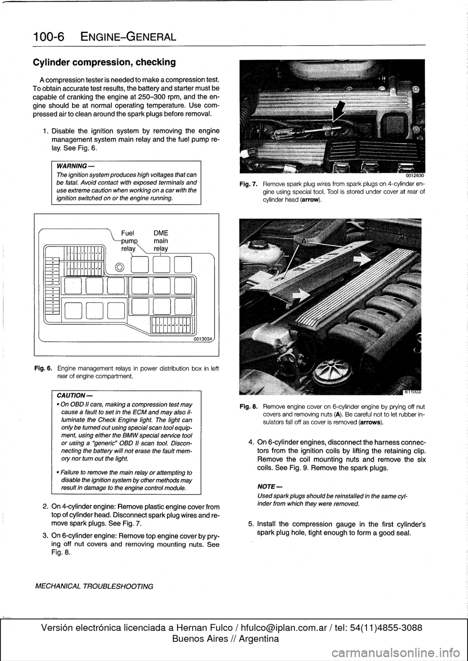
1
.
Disable
the
ignítion
system
by
removing
the
engine
management
system
main
relay
and
the
fuel
pump
re-
¡ay
.
See
Fig
.
6
.
WARNING
-
The
ignítion
system
produces
high
voltages
that
canbe
fatal
.
Avoid
contact
with
exposed
termínals
and
useextreme
caution
when
working
on
acar
wíth
the
ignítion
switched
on
or
the
engine
running
.
Fuel
DM
E
pump
main
re
ay
rel
ay
o
oa
ooa
.,
o00
oao
Fig
.
6
.
Engine
management
relays
in
power
distribution
box
inleft
rear
of
engine
compartment
.
CAUTION-
"
On
OBD
11
cars,
making
a
compression
test
may
causea
faultto
set
in
the
ECM
and
may
also
il-
luminate
the
Check
Engine
light
.
The
light
can
only
be
tumed
out
using
special
scan
tool
equip-
ment,using
eíther
the
BMW
specialservíce
tool
or
using
a
"generic"
OBD
11
scan
tool
.
Discon-
necting
the
battery
will
not
erase
the
fault
mem-
orynor
turn
outthe
light
.
0013034,
0012630
Fig
.
7
.
Remove
spark
plug
wires
from
spark
plugs
on
4-cylinder
en-
gine
using
special
tool
.
Tool
is
stored
under
cover
at
rear
of
cylinder
head
(arrow)
.
Fig
.
8
.
Remove
engine
cover
on
6-cylinder
engine
byprying
off
nut
covers
and
removing
nuts
(A)
.
Be
careful
not
to
let
rubber
in-
sulators
fall
off
as
cover
is
removed
(arrows)
.
4
.
On
6-cylinder
engines,
disconnect
the
harness
connec-
tors
from
the
ignítion
coils
by
lifting
the
retaining
clip
.
Remove
the
coil
mounting
nuts
andremove
the
six
coils
.
See
Fig
.
9
.
Remove
the
sparkplugs
.
"
Failure
to
remove
the
main
relay
or
attempting
to
disable
the
ignítion
system
by
other
methods
may
resultin
damage
to
the
engine
control
module
.
NOTE-
Used
sparkplugs
should
be
reinstalled
in
the
same
cyl-
2
.
On
4-cylinder
engine
:
Remove
plastic
engine
cover
from
inder
fromwhich
they
were
removed
.
top
of
cylinder
head
.
Disconnect
spark
plug
wires
and
re-
move
spark
plugs
.
See
Fig
.
7
.
5
.
Insta¡¡
the
compression
gauge
in
the
first
cylinder's
3
.
On
6-cylinder
engine
:
Remove
top
engine
coverby
pry-
spark
plug
hole,
tight
enough
to
form
a
good
seal
.
ing
off
nut
covers
and
removing
mounting
nuts
.
See
Fig
.
8
.
MECHANICAL
TROUBLESHOOTING
Page 49 of 759
eiioo4
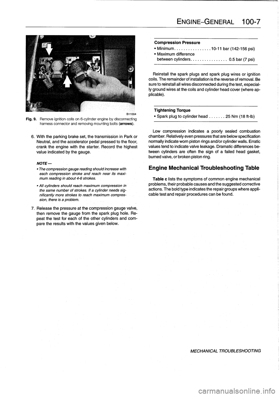
Fig
.
9
.
Remove
ignition
coils
on
6-cylinder
engine
by
disconnecting
harness
connector
and
removing
mounting
bolts
(arrows)
.
NOTE-
"
The
compression
gauge
reading
shoutd
increase
with
each
compression
stroke
and
reach
near
its
maxi-
mum
reading
in
about
4-6
strokes
.
"All
cylinders
shoutdreach
maximum
compression
in
the
same
number
of
strokes
.
If
a
cylinder
needs
sig-
nificantly
more
strokes
to
reach
maximum
compres-
sion,
there
is
a
problem
.
7
.
Release
the
pressure
at
the
compression
gauge
valve,
then
remove
the
gauge
from
the
spark
plughole
.
Re-
peat
the
test
for
each
of
the
other
cylinders
and
com-
pare
the
results
with
the
values
given
below
.
ENGINE-GENERAL
1
:00-
7
Compression
Pressure
"
Minimum
..........
.
.
..
..
10-11
bar
(142-156
psi)
"
Maximum
difference
between
cylinders
..
.....
.........
0
.5
bar
(7
psi)
Reinstall
the
spark
plugs
and
spark
plug
wires
or
ignition
cofs
.
The
remainder
of
installation
is
the
reverse
of
removal
.
Be
sure
to
reihstall
al¡
wires
disconnected
during
the
test,
especial-
¡y
ground
wires
at
the
coils
and
cylinder
head
cover
(where
ap-
plicable)
.
Tightening
Torque
"
Spark
plug
to
cylinder
head
.......
25
Nm
(18
ft-Ib)
Low
compression
indicates
a
poorly
sealed
combustion
6
.
With
the
parking
brake
set,
the
transmission
in
Park
or
chamber
.
Relatively
even
pressures
that
are
below
specification
Neutral,
and
the
accelerator
pedal
pressed
to
the
floor,
normally
indicate
worn
piston
rings
and/or
cylinder
walls
.
Erratic
crank
the
engine
with
the
starter
.
Record
the
highest
values
tend
to
indicate
valve
leakage
.
Dramatic
differences
be
value
indicated
by
the
gauge
.
tween
cylinders
are
often
the
sign
of
a
failed
head
gasket,
bumed
valve,
or
broken
piston
ring
.
Engine
Mechanical
Troubleshooting
Table
Table
c
lists
the
symptoms
of
common
engine
mechanical
problems,
their
probable
causes
and
the
suggested
corrective
actions
.
The
bold
type
indicates
the
repair
groups
where
appli-
cable
test
and
repair
procedures
can
befound
.
MECHANICAL
TROUBLESHOOTING