sensor BMW 318i 1998 E36 Workshop Manual
[x] Cancel search | Manufacturer: BMW, Model Year: 1998, Model line: 318i, Model: BMW 318i 1998 E36Pages: 759
Page 21 of 759
If
steam
is
coming
from
the
engine
compartment
thenthere
is
With
the
engine
and
ignition
off,
check
for
loose
or
corroded
most
likely
a
burst
coolant
hose
or
a
large
leak
in
the
cooling
battery
cables
or
wires
at
the
battery
or
thealtemator
.
Discon-
system
.
To
find
the
leak,
look
for
signs
of
coolant
leakage
on
necting,
cleaning,
and
reinstalling
corroded
wires
and
connec-
hoses,
at
hose
connections,
or
on
the
radiator
.
Let
theengine
tors
may
solve
the
problem
.
Also
check
drive
belt
tension
as
cool
thoroughly,
then
add
coolant
or
water
to
fill
the
system
and
described
in
020
Maintenance
Program
.
start
the
engine
.
If
a
great
deal
of
water
or
coolant
flows
out
of
the
hole,
then
thecarshouldnot
be
driven
until
repairs
are
made
.
lf
there
is
slight
seepage,
then
it
may
be
possible
to
drive
TOWi
ng
a
short
distance,
adding
coolant
as
needed
.
The
cars
covered
by
this
manual
should
be
towed
witha
tow
truck
using
wheel
lift
or
flat
bed
equipment
.
Do
not
tow
thecar
on
all
four
wheels
except
for
very
short
distances
to
move
it
to
a
safe
place
.
If
thered
engine
oil
pressure
warning
light
illuminates,
imme-
diately
stop
thecar
and
turn
off
the
engine
.
Have
the
vehicle
A
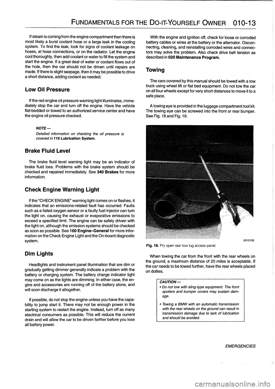
towing
eye
is
provided
in
the
luggage
compartment
tool
kit
.
flat-bedded
or
towed
to
an
authorized
service
center
and
have
The
towing
eye
can
be
screwed
into
the
front
or
rear
bumper
.
the
engine
oil
pressure
checked
.
See
Fig
.
18
and
Fig
.
19
.
Low
Oil
Pressure
NOTE-
Detafed
information
on
checking
the
oil
pressure
is
covered
ín
119
Lubrication
System
.
Brake
Fluid
Leve¡
The
brake
fluid
leve¡
warning
light
may
bean
indicator
of
brake
fluid
loss
.
Problems
with
the
brakesystem
should
be
checked
and
repaired
immediately
.
See
340Brakes
for
more
information
.
Check
Engine
Warning
Light
Dim
Lights
FUNDAMENTALS
FOR
THE
DO-IT
YOURSELF
OWNER
010-13
If
the
"CHECK
ENGI
NE"
warning
light
comes
on
or
flashes,
it
indicates
that
an
emissions-related
fault
has
occurred
.
Faults
suchas
a
failed
oxygen
sensor
or
a
faultyfuelinjector
can
tum
the
light
on,
causing
the
exhaust
or
evaporative
emissions
to
exceed
a
specified
limit
.
The
engine
can
be
safely
driven
with
the
light
on,
although
the
emission
systems
should
be
checked
assoonas
possible
.
See
100
Engine-General
for
more
infor-
mation
on
the
Check
Engine
Light
and
the
On-board
diagnostic
system
.
Headlights
and
instrument
panel
illuminationthat
are
dim
or
gradually
getting
dimmer
generally
indicate
a
problem
with
the
battery
or
charging
system
.
The
battery
charge
indicator
light
may
come
on
as
the
lights
are
dimming
.
In
either
case,
theen-
gine
and
accessories
are
running
off
of
the
battery
alone,
and
will
soon
discharge
it
altogether
.
If
possible,
do
not
stop
the
engine
unless
you
have
the
capa-
bility
to
jump
start
¡t
.
There
may
not
be
enough
power
in
the
starting
system
torestart
the
engine
.
Instead,turn
off
as
many
electrical
consumers
as
possible
.
This
will
reduce
the
current
drain
and
will
allow
thecar
to
be
driven
farther
before
you
lose
all
battery
power
.
Fig
.
18
.
Pry
open
rear
tow
lúg
access
panel
.
When
towingthecar
from
the
front
with
the
rear
wheelson
the
ground,
a
maximum
distance
of
20
miles
is
acceptable
.
If
thecar
needs
to
be
towed
further,
have
the
rear
wheels
placed
on
dollies
.
CA
UTION-
"
Do
not
tow
with
sling-type
equipment
The
front
spoilers
andbumper
covers
may
sustain
dam-
age
.
"
Towínga
BMW
with
an
automatic
transmission
with
the
rear
wheelson
the
ground
can
resuft
in
transmission
damage
due
to
lackof
lubrication
and
should
be
avoided
.
0013128
EMERGENCIES
Page 23 of 759
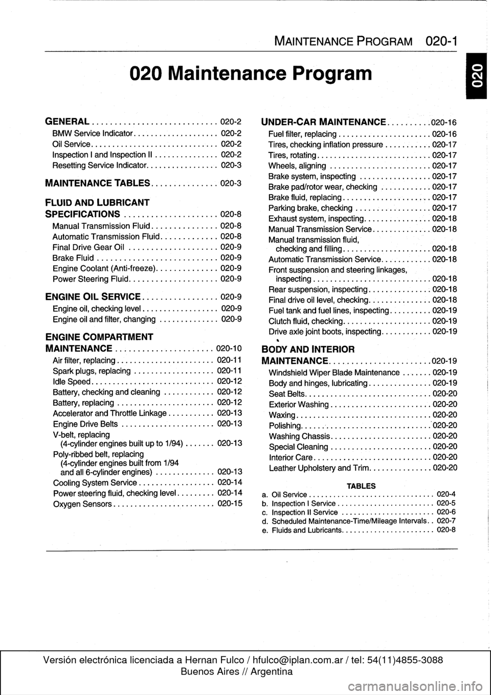
020
Maintenance
Program
GENERAL
.
.
...
.
.
.
...
.
.
.
.
.
.
.
.
.
.
.
...
.
..
020-2
BMW
Service
Indicator
......
..
....
..
...
..
.
020-2
Oil
Service
.....
.
..........
..
...
...
...
..
.
020-2
Inspection
I
and
Inspection
II
.
..
....
..
...
..
.
020-2
Resetting
Service
Indicator
....
.
....
..
...
..
.
020-3
MAINTENANCE
TABLES
..
.
.
.
.
.
........
020-3
FLUID
AND
LUBRICANT
SPECIFICATIONS
.
.
.
.
.
.
.
...
.
.
.
....
.
...
020-8
Manual
Transmission
Fluid
..
.
.
.
.
.
....
.
.
.
.
020-8
Automatic
Transmission
Fluid
.
.
.
.
.
....
.
.
.
.
020-8
Final
Drive
Gear
Oil
................
.
.
.
.
020-9
Brake
Fluid
.
.
.
.
.
................
.
.
.
.
020-9
Engine
Coolant
(Anti-freeze)
.
.
...
.
....
.
.
.
.
020-9
Power
Steering
Fluid
........
..
......
.
.
.
.
020-9
ENGINE
OIL
SERVICE
.
.
...
.
.
.
...
.
.
.
.
.
.
020-9
Engine
oil,
checking
leve¡
..
...
...
..
........
020-9
Engine
oil
and
filter,
changing
....
.
......
.
..
020-9
ENGINE
COMPARTMENT
MAINTENANCE
...
.
.
.
.
.
.
.
.
.
.
.
.
.
......
020-10
Air
filter,
replacing
.
...
...
.
.....
.
.....
.
...
020-11
Spark
plugs,
replacing
...
.
......
.
...
..
...
020-11
¡dle
Speed
.
..
...
...
....
.
......
.
...
..
...
020-12
Battery,
checking
and
cleaning
.......
..
...
020-12
Battery,
replacing
.
.....
.
.....
.
.....
..
...
020-12
Accelerator
and
Throttle
Linkage
.
.....
..
...
020-13
Engine
DriveBelts
.....
.
....
..
...
...
...
.
020-13
V-belt,
replacing
(4-cylinder
engines
built
up
to
1/94)
..
....
.
020-13
Poly-ribbed
belt,
replacing
(4-cylinder
engines
built
from
1194
and
all
6-cylinder
engines)
.
.
....
..
......
020-13
Cooling
System
Service
.
...
..
....
..
....
..
020-14
Power
steering
fluid,
checking
leve¡
.
..
....
.
.
020-14
Oxygen
Sensors
....
...
..
..
....
.
.....
.
.
020-15
MAINTENANCE
PROGRAM
020-1
UNDER-CAR
MAINTENANCE
.
..
.
...
.
.
.020-16
'
Fuel
filter,
replacing
...
.
.....
..
.....
..
..
.020-16
Tires,
checking
inflation
pressure
.
.....
.
....
020-17
Tires,
rotating
...
..
.....
..
....
..
....
.
....
020-17
Wheels,
aligning
..
.....
.
...........
.
....
'020-17
Brake
system,
inspecting
.
.
....
.
.....
..
...
020-17
Brake
pad/rotor
wear,checking
.
......
.
....
020-17
Brake
fluid,
replacing
.........
..
.
..
..
.
020-17
Parking
brake,
checking
......
.
.....
..
....
020-17
Exhaust
system,
inspecting
....
..
.....
.
...
.020-18
Manual
Transmission
Senrice
..
..
.....
.
....
020-18
Manual
transmission
fluida
checking
and
filling
..
.
....
..
.
.
..
..
....
020-18
AutomaticTransmission
Service
.
....
...
....
020-18
Front
suspension
and
steeringlinkages,
inspecting
..
.
:.....
.
....
..
.....
..
...
.
.020-18
Rear
suspension,
inspecting
.
..
...
...
....
..
020-18
Final
drive
oil
leve¡,
checking
.
.
.
...
....
...
..
020-18
Fuel
tank
and
fuel
lines,
inspecting
.
.....
....
020-19
Clutch
fluid,
checking
...
...
...
...
....
.....
020-19
Drive
axle
joint
boots,
inspecting
...
..
.....
..
020-19
BODY
AND
INTERIOR
MAINTENANCE
.
.
.
.
.
.
.
.
.
.
.
.
.
.
.
.
.
.
...
.
.020-19
Windshield
Wiper
Blade
Maintenance
....
.
.
020-19
Body
and
hinges,
lubricating
.
.....
..
......
.
020-19
Seat
Belts
...
..
...
...
...
..
.....
..
.....
.
.
020-20
Exterior
Washing
..
...
...
..
.
.
...
..
......
.020-20
Waxing
.....
..
...
...
...
..
.....
..
.......
020-20
Polishing
..
...
...
...
....
..
..........
..
.
.'020-20
Washing
Chassis
.
...
....
.
....
..
.....
.
...
020-20
Special
Cleaning
.
.
.....
..
...
.
.....
..
..
.020-20
Interior
Care
.
....
..
....
..
..
.
.
......
.
...
020-20
Leather
Upholstery
and
Trim
...
..
....
...
...
020-20
TABLES
a
.
Oil
Service
......
...
.
..
.............
...
---
020-4
b
.
Inspection
1
Service
..
.
.
.............
....
...
020-5
c
.
Inspection
11
Service
.
.
...
...........
..
.
..
..
020-6
d
.
Scheduled
Maintenance-Time/Mileage
Intervals
..
020-7
e
.
Fluids
and
Lubricants
..
...
...........
.....
..
020-8
Page 27 of 759
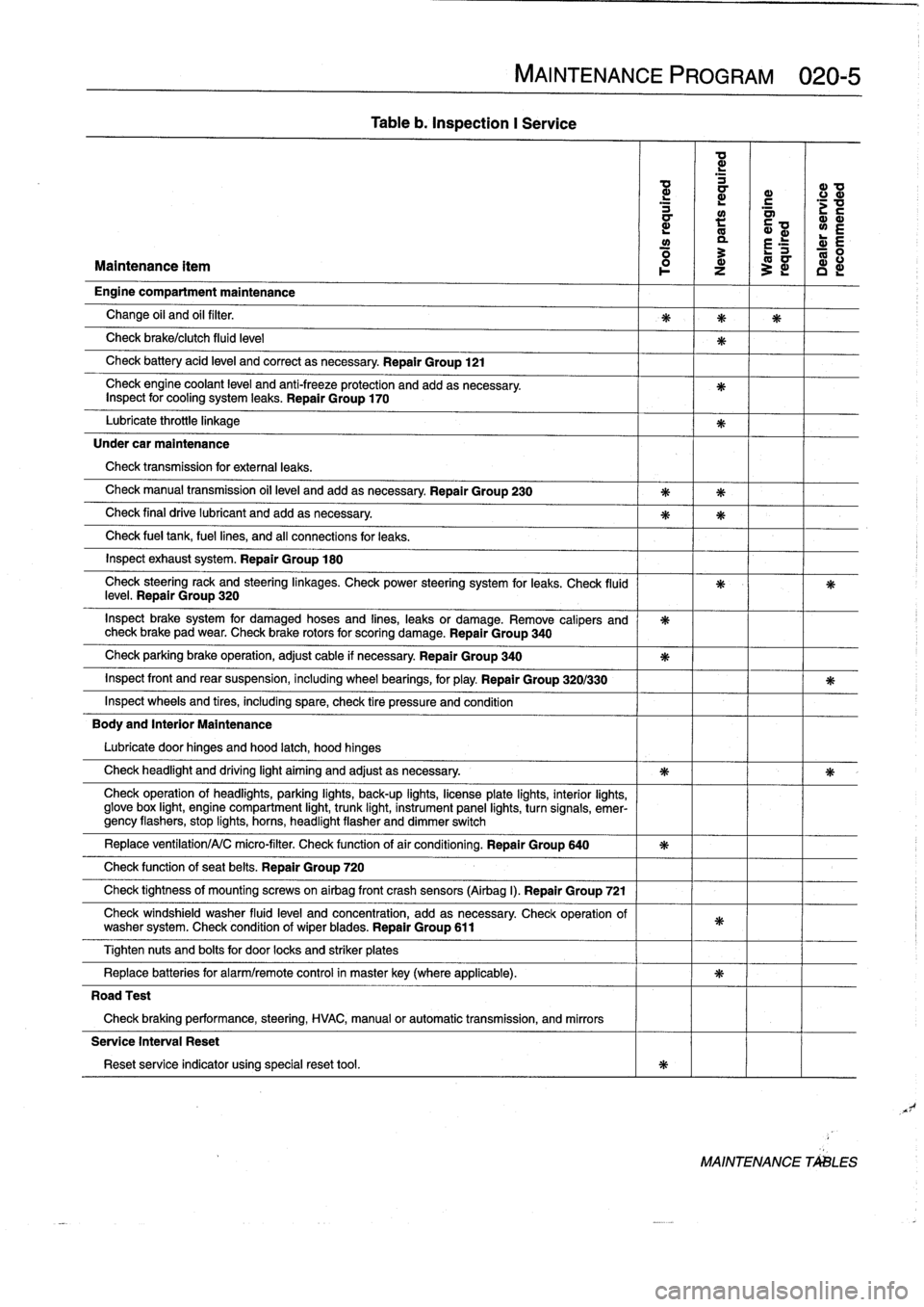
Table
b
.
Inspection
I
Service
MAINTENANCE
PROGRAM
020-5
ad
d
d
ID
a
r
c
d
a~
;v
a
:
Q~
wE
y
a
r
E
R
:
L-
0
Maintenance
ítem
1
z
3
~
c
d
Engine
compartment
maintenance
Change
oil
and
oil
filter
.
Check
brake/clutch
fluid
leve¡
Check
battery
acid
leve¡
and
correct
asnecessary
.
Repair
Group
121
Check
engine
coolant
level
and
anti-freeze
protection
and
addasnecessary
.
Inspect
for
cooling
system
leaks
.
Repair
Group
170
Lubricate
throttie
linkage
Under
car
maintenance
Check
transmission
for
externa¡
leaks
.
Check
manual
transmission
oil
leve¡
andadd
asnecessary
.
Repair
Group
230
Check
final
drive
lubricant
and
addasnecessary
.
Check
fue¡
tank,
fuel
lines,
and
all
connections
for
leaks
.
Inspect
exhaust
system
.
Repair
Group
180
Check
steeringrack
and
steeringlinkages
.
Check
power
steering
system
for
leaks
.
Check
(luid
leve¡
.
Repair
Group
320
Inspect
brake
system
for
damaged
hoses
and
fines,
leaks
or
damage
.
Remove
calipers
and
check
brake
pad
wear
.
Check
brake
rotors
for
scoring
damage
.
Repair
Group
340
Check
parking
brake
operation,
adjust
cable
if
necessary
Repair
Group
340
Inspect
front
and
rear
suspension,
including
wheel
bearings,
for
play
.
Repair
Group
320/330
Inspect
wheelsand
tires,
including
spare,
check
tire
pressure
and
condition
Body
and
Interior
Maintenance
Lubricate
door
hinges
and
hood
latch,
hood
hinges
Check
headlight
and
driving
light
aiming
and
adjust
as
necessary
.
Check
operation
of
headlights,
parking
lights,
back-up
fights,
licenseplate
lights,
interior
lights,
glove
box
light,
engine
compartment
light,
trunk
light,
instrument
panel
lights,
turnsignals,
emer-gency
flashers,
stop
fights,
horas,
headlight
flasher
and
dimmer
switch
Replace
ventilation/A/C
micro-filter
.
Check
functionof
air
conditioning
.
Repair
Group
640
Check
function
of
seat
belts
.
Repair
Group
720
Check
tightness
of
mountfng
screws
on
airbag
front
crash
sensors
(Airbag
I)
.
Repair
Group
721
Check
windshield
washer
fluid
leve¡
and
concentration,
add
as
necessary
Check
operation
of
washer
system
.
Check
condition
of
wiperblades
.
Repair
Group
611
Tighten
nuts
and
bolts
for
door
locks
and
striker
plates
Replace
batteries
for
alarm/remote
control
in
masterkey(where
applicable)
.
Road
Test
Check
braking
performance,
steering,
HVAC,
manual
or
automatic
transmission,
and
mirrors
Service
Interval
Reset
Reset
service
indicator
using
specialreset
tool
.
MAINTENANCE
TALES
Page 29 of 759
d
a
d
_
L
G>
G1
a
N
.
G1
Ñ
N
N
O
.
r
d
Maintenance
ítem
°
~
Z
~
i
I
D
i
Body
and
Interior
Maintenance
(cont
.)
Replace
ventilation/A/C
micro-filter
.
Check
function
of
air
conditioning
.
Repair
Group
640
Check
function
of
seat
belts
.
Repair
Group
720
Check
windshield
washer
fluid
level
and
concentration,
add
asnecessary
.
Check
operation
of
washer
system
.
Check
condition
of
wiperblades
Repair
Group
611
Tighten
nuts
and
belts
for
door
locks
and
striker
plates
.
Replace
batteries
for
alarm/remote
control
in
masterkey
(where
applicable)
.
Check
ground
connection
(mounting
screws)
of
SRS
(airbag)
front
sensor
to
body,
if
applicable
.
Repair
Group
721
Road
Test
Check
braking
performance,
steering,
HVAC,
manual
or
automatic
transmission,
and
mirrors
Service
Interval
Reset
Reset
service
indicator
using
specialreset
tool
.
Maintenance
ítem
Replace
oxygen
sensor
.
Repair
Group
180
1992-1994
1995-
on
Flush
and
replace
brake
fluid/clutch
fluid
.
Repair
Group
340
Drain
and
flush
cooling
system
and
replace
coolant
.
Repair
Group
170
1992-19961997-1998
Anti-corrosion
warranty
inspection
.
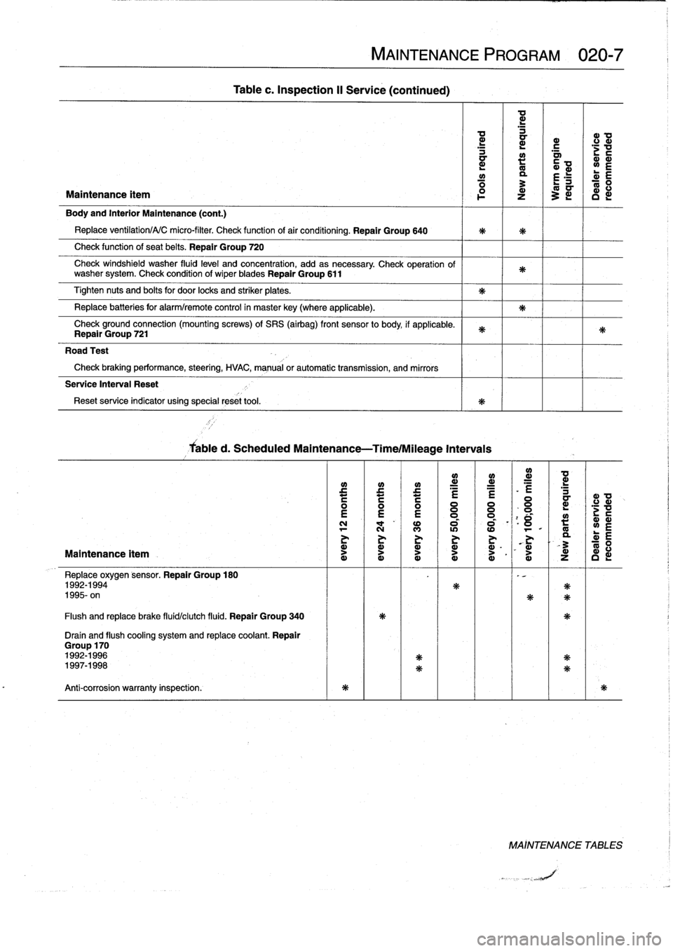
Tablec
.
Inspection
II
Service
(continued)
Cabled
.
Scheduled
Maintenance-Time/Mileage
Intervais
MAINTENANCE
PROGRAM
020-7
e
~
e
e
i
:
l=
N
l
"
NM
I
«)
al
aN
-
11
>
O
Ó
I
Ó
I`
Ó
d
Ny
.
0
°
_
VÑ
Ñ
Ñ
1
ZG
NN
MAÍNTENANCE
TABLES
Page 37 of 759
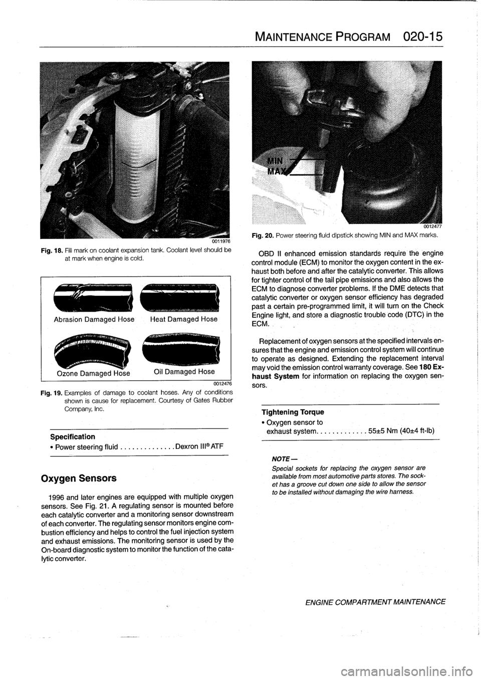
Fig
.
18
.
Fill
mark
on
coolant
expansion
tank
.
Coolant
level
should
be
at
mark
when
engine
ís
cold
.
.
..
e
..
.-
..
~
..
.-
.
Ozone
Damaged
Hose
0012476
Fig
.
19
.
Examples
of
damage
to
coolant
hoses
.
Any
of
conditions
shown
is
cause
for
replacement
.
Courtesy
of
Gates
Rubber
Company,
Inc
.
Specification
"
Power
steering
fluid
..........
.
...
Dexron
III®ATF
Oxygen
Sensors
1996
and
later
engines
are
equipped
withmultiple
oxygen
sensors
.
See
Fig
.
21
.
A
regulating
sensor
is
mounted
before
each
catalytic
converter
and
amonitoring
sensor
downstream
of
each
converter
.
The
regulating
sensor
monitors
engine
com-
bustion
efficiency
and
helps
to
control
the
fuel
injection
system
and
exhaust
emissions
.
The
monitoring
sensor
is
usedby
the
On-board
diagnostic
system
to
monitor
the
function
of
the
cata-
lytic
converter
.
MAINTENANCE
PROGRAM
020-
1
5
NOTE-
5pecialsockets
for
replacingthe
oxygen
sensor
are
available
from
most
automotive
parts
stores
.
The
sock-
et
has
agroove
cut
down
one
side
to
allow
the
sensor
to
be
installed
without
damaging
the
wire
hamess
.
Fig
.
20
.
Power
steering
fluid
dipstick
showing
MIN
and
MAX
marks
.
OBD
II
enhanced
emission
standards
require
the
engine
control
module
(ECM)
to
monitor
the
oxygen
content
in
theex-
haust
bothbefore
and
after
the
catalytic
converter
.
This
allows
for
tightercontrol
of
the
tail
pipe
emissions
and
also
allowsthe
ECM
to
diagnose
converter
problems
.
lf
the
DME
detects
that
catalytic
converter
or
oxygen
sensor
efficiency
has
degraded
past
a
certain
pre-programmed
limit,
it
will
turn
on
the
Check
Engine
light,
and
store
a
diagnostic
trouble
code
(DTC)
in
the
ECM
.
Replacement
of
oxygen
sensors
at
the
specified
intervals
en-
sures
that
the
engine
and
emission
control
system
wíll
continue
to
operate
as
designed
.
Extending
the
replacement
interval
may
void
the
emission
control
warranty
coverage
.
See
180
Ex-
haust
System
for
information
on
replacing
the
oxygen
sen-
sors
.
Tightening
Torque
"
Oxygen
sensor
to
exhaust
system
........
.
.
.
..
55±5
Nm
(40±4
ft-Ib)
ENGINE
COMPARTMENT
MAINTENANCE
Page 38 of 759
020-
1
6
MAINTENANCE
PROGRAM
Fuel
filter,
replacing
Oxygen
sensor
(regulating)
\
Catalytic
Oxygen
sensor
convertor
(monitoring)
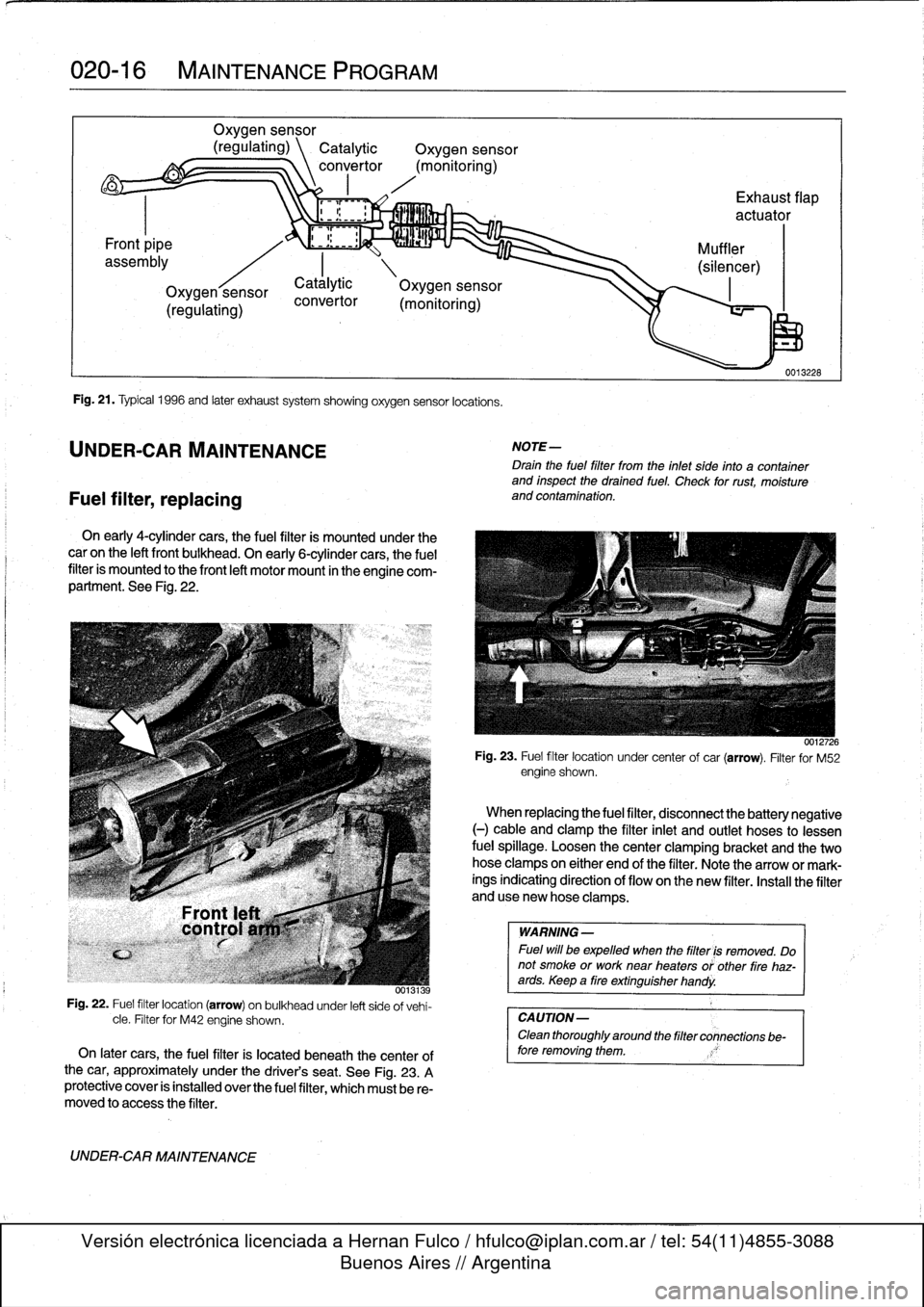
Fig
.
21
.
Typical
1996
and
later
exhaust
system
showing
oxygen
sensor
locations
.
UNDER-CAR
MAINTENANCE
convertor
On
early
4-cylínder
cars,
the
fuel
filter
is
mounted
under
the
caron
the
left
front
bulkhead
.
On
early
6-cylínder
cars,
the
fuel
filter
is
mounted
to
the
front
left
motor
mount
in
theengine
com-
partment
.
See
Fig
.
22
.
0013139
Fig
.
22
.
Fuel
filter
location
(arrow)
on
bulkheadunder
left
side
of
vehi-
cle
.
Filter
for
M42
engine
shown
.
On
later
cars,
the
fuel
filter
is
located
beneath
the
centerof
the
car,
approximately
under
the
driver's
seat
.
See
Fig
.
23
.
A
protective
cover
is
installed
overthe
fuel
filter,
which
must
be
re-
moved
to
access
the
filter
.
UNDER-CAR
MAINTENANCE
Exhaust
flap
actuator
(monitoring)
NOTE-
Drain
the
fuel
filter
trom
the
inlet
side
into
a
container
and
inspect
the
drained
fuel
.
Check
for
rust,
moisture
and
contamination
.
WARNING
-
Fuel
will
be
expelled
when
the
filter
is
removed
.
Do
not
smoke
or
worknear
heaters
or'other
fire
haz-ards
.
Keep
a
tire
extinguisher
handy
.
CAUTION-
Clean
thoroughly
around
the
filter
connections
be-
fore
removing
them
.
0012726
Fig
.
23
.
Fuel
filter
location
under
center
of
car
(arrow)
.
Filter
for
M52
engine
shown
.
Catálytic
\
Oxygen
sensor
When
replacing
the
fuel
filter,
disconnect
the
battery
negative
(-)
cable
and
clamp
the
filter
inlet
and
outlet
hoses
to
lessen
fuel
spillage
.
Loosen
thecenter
clamping
bracket
and
the
two
hoseclampson
either
end
of
the
filter
.
Note
the
arrow
or
mark-
ings
indicating
direction
of
flow
on
the
new
filter
.
Install
the
filter
anduse
new
hose
clamps
.
Page 43 of 759
GENERAL
.
.....
.
.
.
.
.
.
.
...
.
.
.
.
.
.
.
.
.
...
100-1
Cylinder
Block
and
Crankshaft
.
.
.
.
.
.
.
.
.
...
100-1
Connecting
Rods
and
Pistons
.
.
.
.
.
.
.
.
.
.
.
.
.
100-1
Cylinder
Head
and
Valvetrain
.
.
.
.
.
.
.
.
.
.
.
.
.
100-2
VANOS
(Variable
Valve
Timing)
.
.
.
.
.
.
.
.
...
100-2
DISA
(Dual
Resonance
Intake
System)
.
.
.
.
.
100-3
Engine
Management
System
.
.
.
.
.
.
.
.
.
.
.
.
.
100-3
Ignition
......
.
.
.
.........
.
.
.
.
.
.
.
.
.
.
.
.
100-5
Fuel
Delivery
..
.
.
.
.....
.
...
.
.
.
.
.
.
.
.
.
.
.
.
100-5
Cooling
System
.
...........
.
.
.
.
.
.....
.
.
100-5
Lubrication
System
.........
.
.
.
.
.
.
.
.
.
.
.
.
100-5
MECHANICALTROUBLESHOOTING
.
.
.
.
100-5
Warnings
and
Cautions
..
.
...
.
.
.
.
.
.
.
.
.
.
.
.
100-5
Cylinder
compression,
checking
.
.
.
.
.
.
.
.
.
.
.
100-6
EngineMechanical
Troubleshooting
Table
.
.
.
100-7
DRIVEABILITY
TROUBLESHOOTING
...
100-8
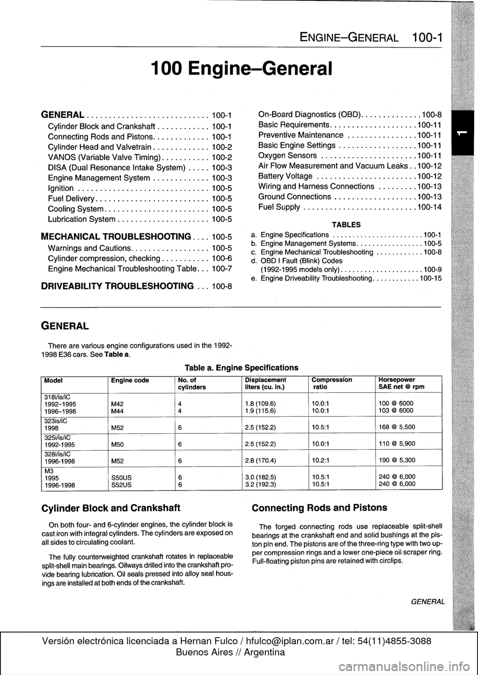
GENERAL
There
are
various
engíne
configurations
used
in
the
1992-
1998
E36
cars
.
See
Table
a
.
On
both
four-
and
6-cylinder
engines,
the
cylinder
block
is
cast
¡ron
with
integral
cyiinders
.
The
cyiinders
are
exposed
on
all
sides
to
circulating
coolant
.
The
fully
counterweighted
crankshaft
rotates
in
replaceable
split-shell
main
bearings
.
Oiiways
drilled
into
the
crankshaft
pro-
vide
bearing
lubrication
.
O¡I
seals
pressed
into
alloy
sea¡
hous-
ings
are
installedat
both
ends
of
the
crankshaft
.
100
Engine-General
Tablea
.
Engine
Specifications
ENGINE-GENERAL
100-1
On-Board
Diagnostics
(OBD)
...
.
.
.
.
.
.
.
.
.
.
.
100-8
Basic
Requirements
....
.
.
.
...
.
.
.
.
.
....
.100-11
Preventive
Maintenance
......
.
.
.
.
.
.....
100-11
Basic
Engine
Settings
..
.
.....
.
.
.
.
.
.....
100-11
Oxygen
Sensors
.
.
.
...
.
.
.
...
.
.
.
.
.
....
.100-11
Air
Flow
Measurement
and
Vacuum
Leaks
.
.100-12
Battery
Voltage
.
.
...........
.
.
.
.
.
.....
100-12
Wiring
and
Harness
Connections
.
.
.
.
.....
100-13
Ground
Connections
...
.
.....
.
.
.
.
.
.....
100-13
Fue¡
Supply
....
.
...........
.
.
..
.....
.100-14
TABLES
a
.
Engine
Specifications
...
...
...........
.
..
..
.100-1
b
.
Engine
Management
Systems
..
..
...........
..
100-5
c
.
Engine
Mechanical
Troubleshooting
..........
.
.
100-8
d
.
OBD
1
Fault
(Blink)
Codes
(1992-1995
models
only)
.
...
..
..
..........
..
.100-9
e
.
Engine
Driveability
Troubleshooting
...........
.100-15
Model
Engine
code
No
.
of
Dispiacement
Compression
Horsepower
cyiinders
liters
(cu
.
in
.)
ratio
SAE
net
@
rpm
318i/is/¡C
1992-1995
M42
4
1
.8
(109
.6)
10
.0
:1
100
@
6000
1996-1998
M44
4
1
.9
(115
.6)
~
10
.0
:1
103
@
6000
323ís/iC
1998
M52
6
2
.5
(152
.2)
10
.5
:1
168
@
5,500
325i/is/iC
1992-1995
M50
6
2
.5
(152
.2)
10
.0
:1
110
@
5,900
328i/is/iC
1996-1998
M52
6
2
.8
(170
.4)
10
.2
:1
190
@
5,300
M3
1995
S50US
6
3
.0
(182
.5)
10
.5:1
240
@
6,000
1996-1998
S52US
6
3
.2
(192
.3)
10
.5:1
240
@
6,000
Cylinder
Block
and
Crankshaft
Connecting
Rods
and
Pistons
The
forged
connecting
rods
use
replaceable
split-shell
bearings
at
the
crankshaft
endand
solid
bushings
at
the
pis-
ton
pin
end
.
The
pistonsare
of
the
three-ring
typewith
two
up-
per
compression
rings
and
a
lowerone-piece
o¡i
scraper
ring
.
Fui¡-floating
piston
pins
are
retained
with
circlips
.
GENERAL
Page 46 of 759
100-4
ENGINE-GENERAL
'
TEMP
PRECAT
POST
CAT
OXYGENSENSOR
HEATING
#
.
THROTTLE
POSITION
FUEL
INJECTOR
CONTROL
(SEQUENTIAL)
OPERATING
POWER
00
CAMSHAFT
POSITION
SENSOR
ECM
I
MAIN
GROUND
RELAY
J_
-
AC
COMPRESSOR
RELAY
CONTROL
TERMINAL
15
MEMORY
POWER
FUEL
PUMP
RELAY
CONTROL
AUX
GROUND
P
CRANKSHAFT
POSITION
dESENSOR
INTAKE
AIR
ENGINE
COOLANT
TEMP
FUEL
TANK
PRESSURE
SENSOR
S-EML
S-MSR
ASC
S-ASC
VEHICLE
SPEED
LOW
FUEL
LEVEL
A/C
SWITCH
ON
(AC)
E36
IHKA
COMPRESSOR"ON"
SIGNAL
(KO)
INDIVIDUAL
SERIAL
NUMBER
MS41
.1
SECONDARY
AIR
1NJECTION
AIR
PUMP®
RELAY
CONTROL
IDLE
CONTROL
VALVE
'M
FUEL
INJECTION
(TI)
ENGINE
SPEED
(TD)
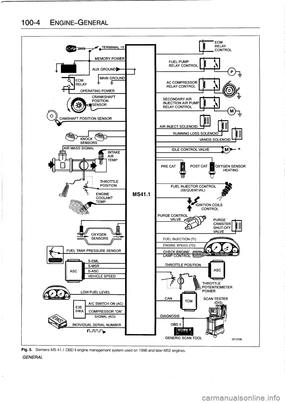
Fig
.
5
.
Siemens
MS
41
.1
OBD
II
engine
management
systemusedon
1996
and
later
M52
engines
.
GENERAL
IGNITION
COILS
CONTROL
L
r"Q
if~
CIYVFIYC
CHE
AMP
CONTROL
ENGINE
THROTTLE
POSITION
6
ECM
RELAY
CONTROL
ASC
THROTTLE
..
:
.
.
..
-11
1Q\\\
POTENTIOMETER
POWER
CAN
TCM
II
SCAN
(DES
;
ER
DIAGNOSIS
OBD
II
I
II
GENERIC
SCANTOOL
0012596
Page 50 of 759
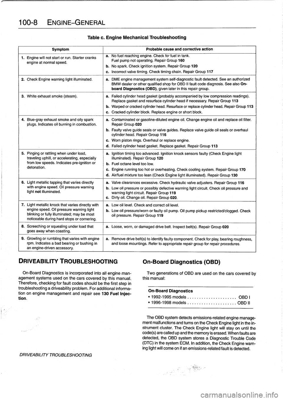
100-8
ENGINE-GENERAL
Symptom
1
Probable
cause
and
correctiveaction
1
.
Engine
will
not
start
or
run
.
Starter
cranks
a
.
No
fuel
reaching
engine
.
Check
forfuelin
tank
.
engine
at
normal
speed
.
Fuel
pump
notoperating
.
Repair
Group
160
b
.
No
spark
.
Check
ignition
system
.
Repair
Group
120
c
.
Incorrect
valve
timing
.
Check
timing
chain
.
Repair
Group
117
2
.
Check
Engine
warning
light
illuminated
.
a
.
DME
engine
management
system
self-diagnostic
fault
detected
.
Sea
an
authorized
BMW
dealer
or
other
qualified
shop
for
OBD
II
fault
code
diagnosis
.
See
also
On-
board
Diagnostics(OBD),
given
later
inthis
repair
group
.
3
.
White
exhaust
smoke
(steam)
.
a
.
Failed
cylinder
head
gasket
(probably
accompanied
bylowcompression
readings)
.
Replace
gasket
and
resurface
cylinder
head
if
necessary
.
Repair
Group
113
4
.
Blue-gray
exhaust
smoke
and
oily
spark
a
.
Contaminated
or
gasoline-diluted
engine
oil
.
Change
engine
oil
and
replace
oil
filter
.
plugs
.
Indicates
oii
burning
in
combustion
.
Repair
Group
020
b
.
Faulty
valve
guide
seals
or
valve
guides
.
Replace
valve
guide
oil
seals
or
overhaul
cylinder
head
.
Repair
Group
116
5
.
Pinging
or
rattling
when
under
load,
a
.
Ignition
timing
too
advanced
.
Ignition
knocksensors
faulty
(CheckEngine
light
traveling
uphill,
or
accelerating,
especially
illuminated)
.
Repair
Group
120fromlow
speeds
.
Indicates
pre-ignition
or
b
.
Fuel
octane
leve¡
toolow
.
detonation
.
c
.
Engine
running
too
hot
or
overheating
.
Check
cooling
system
.
Repair
Group
170
6
.
Light
metallic
tapping
that
varies
directly
with
engine
speed
.
Oil
pressure
warning
light
not
illuminated
.
7
.
Light
metallic
knock
that
varies
directly
with
enginespeed
.
Oil
pressure
warning
light
blinking
or
fully
illuminated
;
may
be
most
noticeable
during
hard
stops
or
cornering
.
8
.
Screeching
or
squealing
under
load
that
a
.
Loose,worn,
or
damaged
drive
belt
.
Inspect
belt(s)
.
Repair
Group
020
goesaway
when
coasting
.
9
.
Growling
or
rumbling
that
varieswith
engine
a
.
Remove
drive
belt(s)toidentifyfaulty
component
.
Check
for
play,
bearing
roughness,
rpm
.
Indicates
abad
bearing
or
bushing
in
and
loose
mountings
.
Refer
to
appropriate
repair
group
for
repair
procedures
.
an
engine-driven
accessory
.
DRIVEABILITY
TROUBLESHOOTING
On-Board
Diagnostics
(OBD)
On-Board
Diagnostics
is
incorporated
into
al¡
engine
man-
Two
generations
of
OBD
are
usedon
thecars
covered
by
agement
systems
used
on
the
cars
covered
by
this
manual
.
this
manual
:
Therefore,
checking
for
fault
codes
should
be
the
first
step
in
troubleshootinga
driveability
problem
.
For
additional
informa-
On-Board
Diagnostics
tion
on
engine
management
and
repair
see130
Fuel
Injec-
tion
.
"
1992-1995models
....
.
..
....
.
..
.......
OBD
I
"
1996-1998models
.
....
..
.
.
.
..
.
........
OBD
II
DRIVEABILITY
TROUBLESHOOTING
Tablec
.
Engine
Mechanical
Troubleshooting
b
.
Warped
or
cracked
cylinder
head
.
Resurface
or
replace
cylinder
head
.
Repair
Group
113
c
.
Cracked
cylinder
block
.
Replace
engine
or
short
block
.
c
.
Worn
piston
rings
.
Overhaul
or
replace
engine
.
d
.
Failed
cylinder
head
gasket
.
Replace
gasket
.
Repair
Group
113
d
.
Air/fuel
mixture
too
lean
(Check
Engine
light
illuminated)
.
Repair
Group
130
a
.
Valveclearances
excessive
.
Check
hydraulic
valve
adjusters
.
Repair
Group
116
b
.
Low
oil
pressure
orpossibly
defective
warning
light
circuit
.
Check
oil
pressure
andwarning
light
circuit
.
Repair
Group
119
c
.
Dirty
oil
.
Change
oil
.
Repair
Group
020
.
a
.
Low
oil
leve¡
.
Check
and
correct
oil
leve¡
.
b
.
Low
oil
pressure/worn
or
faulty
oil
pump
.
Oil
pump
pickup
restricted/clogged
.
Check
oil
pressure
.
Repair
Group
119
The
OBD
system
detects
emissions-related
engine
manage-
ment
malfunctions
and
tucos
on
the
Check
Engíne
lightin
the
in-
strument
cluster
.
TheCheck
Engine
light
will
stay
on
until
the
code(s)are
called
up
and
the
memory
is
erased
.
When
faulty
are
detected,
the
OBD
system
stores
a
Diagnostic
Trouble
Code
(DTC)
in
the
system
ECM
.
In
addition,
the
Check
Engine
warn-
ing
light
will
come
on
if
an
emissions-related
fault
is
detected
.
Page 51 of 759
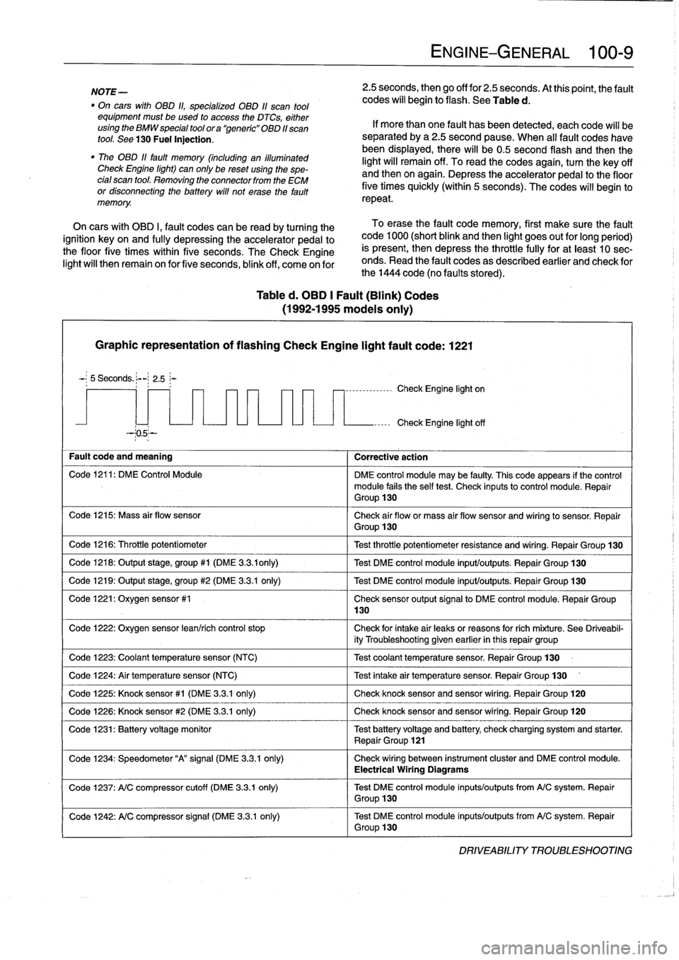
NOTE-
"
On
carswith
OBD
ti,
specialized
OBD
11
scan
tool
equipment
must
be
used
to
access
the
DTCs,
either
using
the
BMW
special
tool
ora
`generic"
OBD
11
scan
tool
.
See
130
Fuel
Injection
.
"
The
08D
11
fault
memory
(including
an
iiluminated
Check
Engine
light)
can
only
be
reset
using
the
spe-
cial
scan
tool
.
Removing
the
connector
from
the
ECM
or
disconnecting
the
battery
will
not
erase
the
fault
memory
.
Table
d
.
OBD
1
Fault
(Blink)
Codes
(1992-1995
modeis
only)
Graphic
representation
of
flashing
Check
Engine
light
fault
code
:
1221
5
Seconds
.
:-
2
.5~-
--05--
Fault
code
and
meaning
1
Corrective
action
Code
1216
:
Throttle
potentiometer
Code
1218
:
Output
stage,
group#1
(DME
3
.3
.ionly)
Code
1219
:
Output
stage,
group
#2
(DME
3
.3.1
only)
Code
1221
:
Oxygen
sensor
#1
Code
1224
:
Air
temperature
sensor
(NTC)
Code
1226
:
Knock
sensor
#2
(DME
3
.3
.1
only)
130
ENGINE-GENERAL
100-
9
2
.5
seconds,
then
go
off
for
2
.5
seconds
.
At
thispoint,
the
fault
codes
will
begin
to
flash
.
See
Table
d
.
If
more
than
one
fault
has
been
detected,
eachcode
will
be
separated
by
a2
.5
second
pause
.
When
al¡
fault
codes
havebeen
displayed,
there
will
be0
.5
second
flash
and
thenthe
light
will
remain
off
.
To
read
the
codes
again,
turn
the
key
off
and
then
on
again
.
Depress
theaccelerator
pedal
to
the
floor
five
times
quickly
(within
5
seconds)
.
The
codes
will
begin
to
repeat
.
On
cars
with
OBD
I,
fault
codes
can
be
read
by
turning
the
To
erase
the
fault
code
memory,
first
make
sure
the
fault
ignition
key
on
and
fully
depressing
theaccelerator
pedal
to
code
1000
(short
blink
and
then
light
goes
out
for
long
period)
the
floor
five
times
within
five
seconds
.
TheCheck
Engine
is
present,
then
depress
the
throttle
fully
for
at
least
10
sec-
light
will
then
remain
on
for
five
seconds,
blink
off,
come
on
for
onds
.
Read
the
fault
codes
as
described
earlier
and
check
for
the
1444
code
(no
faults
stored)
.
-,--------------
Check
Engine
light
on
Check
Engine
light
off
Code
1211
:
DM
E
Control
Module
DME
control
module
may
be
faulty
.
This
code
appears
if
the
control
module
fails
the
self
test
.
Check
inputsto
control
module
.
Repair
Group
130
Code
1215
:
Mass
air
flow
sensor
Check
air
flow
or
mass
air
flow
sensor
and
wiring
to
sensor
.
Repair
Group
130
Test
throttle
potentiometer
resistance
and
wiring
.
Repair
Group
130
Test
DME
control
module
input/outputs
.
Repair
Group
130
Test
DME
control
module
input/outputs
.
Repair
Group
130
Check
sensor
output
signal
to
DME
control
module
.
Repair
Group
Code
1222
:
Oxygen
sensor
lean/rich
control
stop
Check
for
intake
air
leaks
or
reasons
forrich
míxture
.
See
Driveabil-
ity
Troubleshooting
given
earlier
in
this
repair
group
Code
1223
:
Coolant
temperaturesensor
(NTC)
1
Test
coolant
temperature
sensor
.
Repair
Group
130
Test
intake
air
temperature
sensor
.
Repair
Group
130
Code
1225
:
Knock
sensor#1
(DME
3
.3
.1
only)
1
Check
knocksensorand
sensor
wiring
.
Repair
Group
120
Check
knocksensor
and
sensor
wiring
.
Repair
Group
120
Code
1231
:
Batteryvoltage
monitor
Test
battery
voltage
and
battery
check
charging
system
and
starter
.
Repair
Group
121
Code
1234
:
Speedometer
"A"signal
(DME
3
.3
.1
only)
Check
wiring
between
instrument
cluster
and
DME
control
module
.
Electrical
Wiring
Diagrams
Code
1237
:
A/C
compressor
cutoff
(DME
3
.3
.1
only)
Test
DME
control
module
inputs/outputs
from
A/C
system
.
Repair
Group
130
Code
1242
:
A/C
compressor
signal
(DME
3
.3.1
only)
Test
DME
control
module
inputs/outputs
from
A/C
system
.
Repair
Group
130
DRIVEABILITY
TROLIBLESHOOTING