BMW 320i 2001 Owners Manual
Manufacturer: BMW, Model Year: 2001, Model line: 320i, Model: BMW 320i 2001Pages: 211, PDF Size: 2.1 MB
Page 171 of 211
171n
IndexDataTechnologyRepairsCar careControlsOverview
Fuses Microfilter/Activated-charcoal filterThe fuses, their respective ampere
ratings and the equipment in their
circuits are all indicated below the fuse
holder.
To close the fuse holder, snap it into
position at the top and turn the two
fasteners inward.
Do not attempt to repair a burned
fuse or replace it with a fuse
having a different color or amperage
rating. To do this could cause a fire in
the vehicle resulting from a circuit over-
load.<
If a fuse blows repeatedly, refer the
problem to your BMW center for repair.
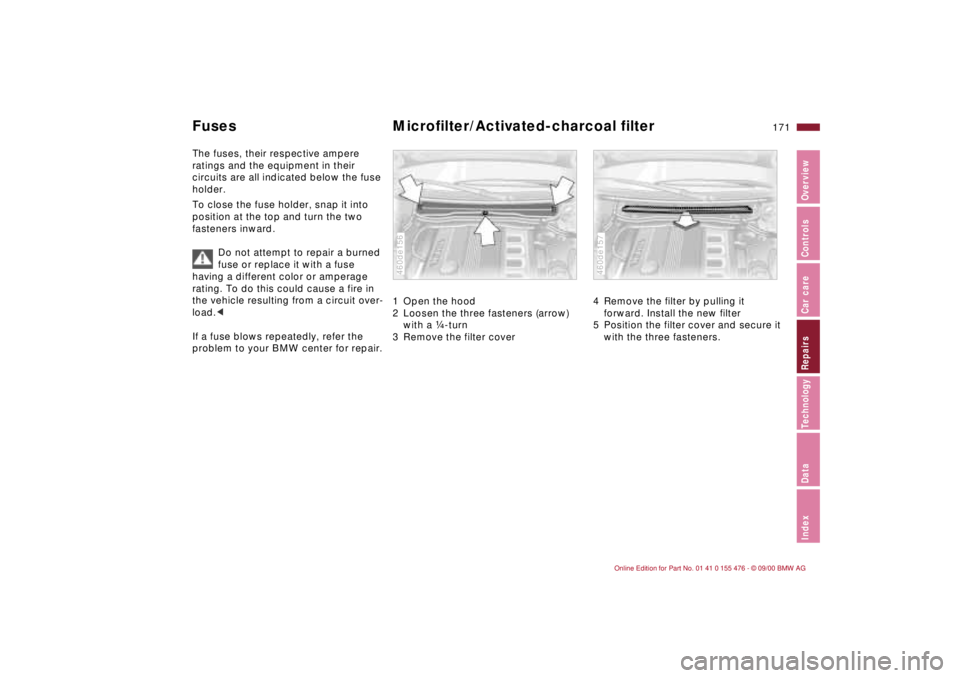
1 Open the hood
2 Loosen the three fasteners (arrow)
with a f-turn
3 Remove the filter cover 460de156
4 Remove the filter by pulling it
forward. Install the new filter
5 Position the filter cover and secure it
with the three fasteners. 460de157
Page 172 of 211
172n
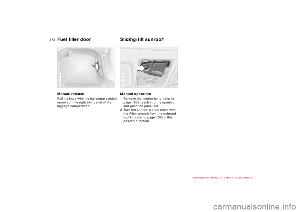
Manual release Pull the knob with the fuel pump symbol
(arrow) on the right trim panel of the
luggage compartment. 460de178
Manual operation 1 Remove the interior lamp (refer to
page 163), reach into the opening
and push the panel out
2 Turn the sunroof's steel crank with
the Allen wrench from the onboard
tool kit (refer to page 158) in the
desired direction.460de183
Fuel filler door Sliding/tilt sunroof
*
Page 173 of 211
173n
IndexDataTechnologyRepairsCar careControlsOverview
Do not use spray starter fluids.
If the battery is discharged, the engine
can be started with the use of two
jumper cables and the battery of
another vehicle. Use only jumper cables
with fully insulated grips on the terminal
clamps.
Do not touch the parts conducting
electrical current while the engine
is running. Failure to comply with this
creates a risk of fatal injury.<
Carefully comply with the following
instructions to avoid personal injury or
damage to one or both vehicles:
1 Be sure that the battery on the
support vehicle is also rated at
12 volts, and that the capacities of
the two batteries (Ah) are roughly
comparable (printed on casing)
2 Leave the discharged battery
connected to the vehicle's electrical
system
3 Make sure that there is no contact
between the bodywork of the two
vehicles Ð this creates a risk of short
circuits
4 Start by connecting the jumper cable
from the positive terminal of the
support vehicle to the positive
terminal connector located in your
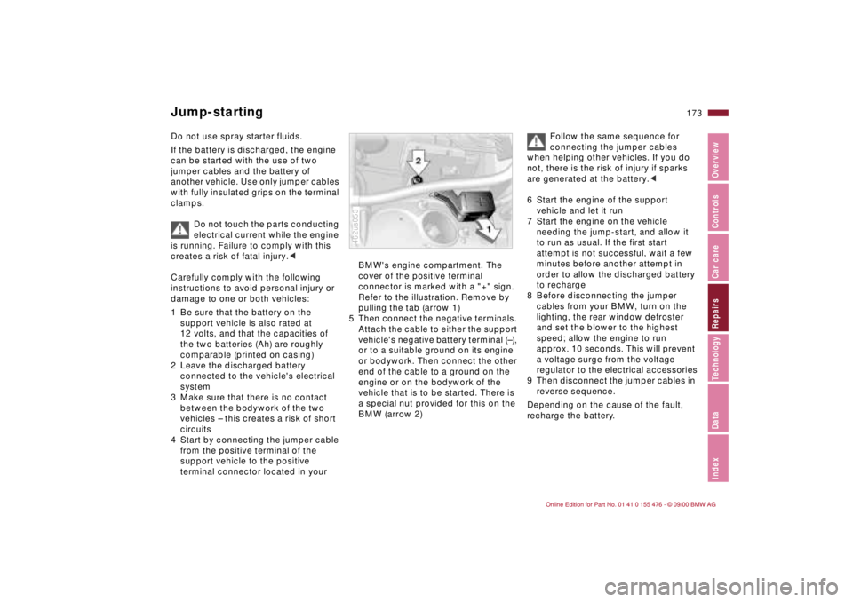
BMW's engine compartment. The
cover of the positive terminal
connector is marked with a "+" sign.
Refer to the illustration. Remove by
pulling the tab (arrow 1)
5 Then connect the negative terminals.
Attach the cable to either the support
vehicle's negative battery terminal (Ð),
or to a suitable ground on its engine
or bodywork. Then connect the other
end of the cable to a ground on the
engine or on the bodywork of the
vehicle that is to be started. There is
a special nut provided for this on the
BMW (arrow 2)462us053
Follow the same sequence for
connecting the jumper cables
when helping other vehicles. If you do
not, there is the risk of injury if sparks
are generated at the battery.<
6 Start the engine of the support
vehicle and let it run
7 Start the engine on the vehicle
needing the jump-start, and allow it
to run as usual. If the first start
attempt is not successful, wait a few
minutes before another attempt in
order to allow the discharged battery
to recharge
8 Before disconnecting the jumper
cables from your BMW, turn on the
lighting, the rear window defroster
and set the blower to the highest
speed; allow the engine to run
approx. 10 seconds. This will prevent
a voltage surge from the voltage
regulator to the electrical accessories
9 Then disconnect the jumper cables in
reverse sequence.
Depending on the cause of the fault,
recharge the battery.
Jump-starting
Page 174 of 211
174n
Towing the vehicleTow fittingThe screw-in tow fitting is stored in the
onboard tool kit; be sure that it remains
in the vehicle at all times. This fitting is
designed for installation in the tow
sockets located at the front and rear of
the vehicle. It is intended for towing on
paved road surfaces only. This fitting
should not be used to pull a vehicle out
of deep snow, mud, sand, etc.
Always comply with all applicable
towing laws and regulations. Access to tow socketsFront:
Use a screwdriver in the upper section
of the recess to press the cover out.460de063
Rear:
Use a screwdriver in the upper section
of the recess to press the cover out.
Screw the tow fitting in completely
and tightly. If you do not, the
threads could be damaged.
Do not tow the vehicle by any compo-
nents of the running gear, or lash them
down in any way. If you do so, the
components could be damaged,
leading to possible accidents.<460de064
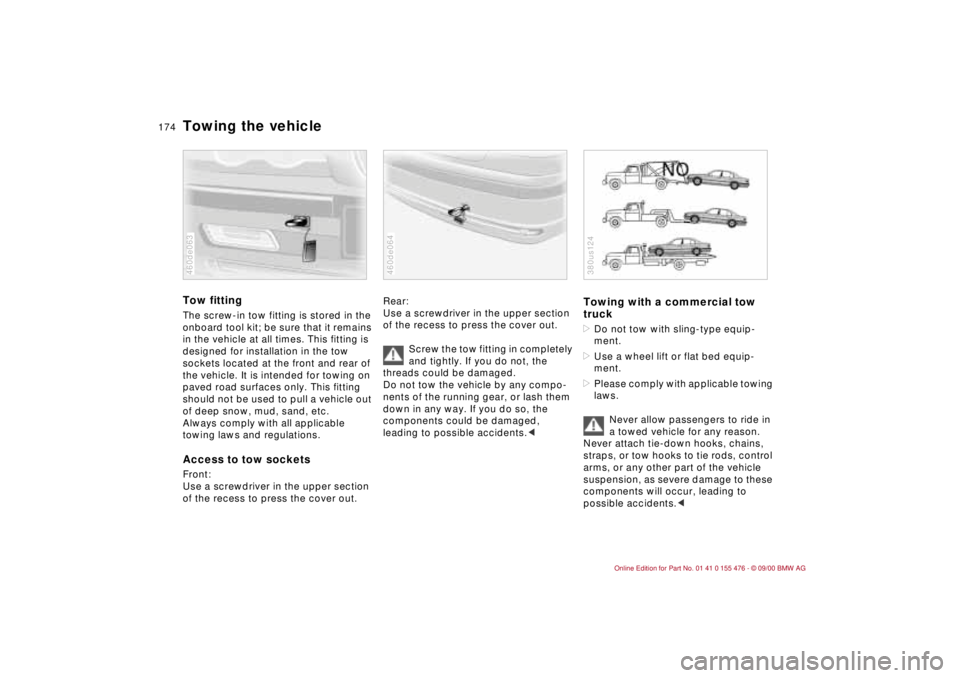
Towing with a commercial tow
truck>Do not tow with sling-type equip-
ment.
>Use a wheel lift or flat bed equip-
ment.
>Please comply with applicable towing
laws.
Never allow passengers to ride in
a towed vehicle for any reason.
Never attach tie-down hooks, chains,
straps, or tow hooks to tie rods, control
arms, or any other part of the vehicle
suspension, as severe damage to these
components will occur, leading to
possible accidents.c380us124
Page 175 of 211
175n
IndexDataTechnologyRepairsCar careControlsOverview
Towing the vehicleBMW 325xi, 330xi: towing the
vehicle with one raised axle only 1 Place the gearshift lever or selector
lever in "Neutral"
2 Switching off the engine
3 Towing speed:
Max. 30 mph (50 km/h)
4 Towing distance:
Max. 95 miles (150 km)
Remove the rear driveshaft for
towing over longer distances with
the front axle lifted; remove the front
driveshaft for towing over longer
distances with the rear axle lifted.
Failure to comply with this will result in
damage to the transfer box.<
Page 176 of 211
176n
Page 177 of 211
Overview
Controls and features
Operation, care
and maintenance
Owner service procedures
Technical data
Index Advanced technology
177n
IndexDataTechnologyRepairsCar careControlsOverview
Adaptive Transmission Control
(ATC)178
Airbags179
Automatic Stability Control plus
Traction (ASC+T)/Dynamic
Stability Control (DSC)180
Radio reception181
Four-wheel drive182
Safety belt tensioner183
Interior rearview mirror
with automatic dimming
feature184
Rain sensor185
Tire Pressure Control (RDC)186
Self-diagnostics187
Xenon lamps188
Technol-
Page 178 of 211
178n
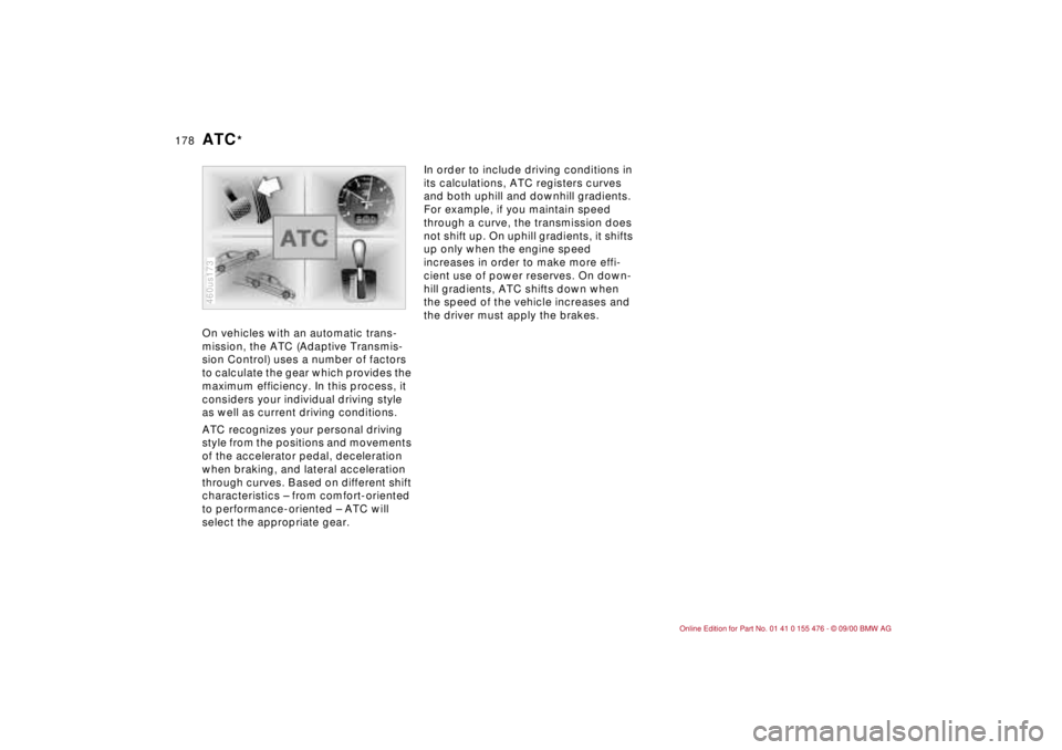
On vehicles with an automatic trans-
mission, the ATC (Adaptive Transmis-
sion Control) uses a number of factors
to calculate the gear which provides the
maximum efficiency. In this process, it
considers your individual driving style
as well as current driving conditions.
ATC recognizes your personal driving
style from the positions and movements
of the accelerator pedal, deceleration
when braking, and lateral acceleration
through curves. Based on different shift
characteristics Ð from comfort-oriented
to performance-oriented Ð ATC will
select the appropriate gear.
460us173
In order to include driving conditions in
its calculations, ATC registers curves
and both uphill and downhill gradients.
For example, if you maintain speed
through a curve, the transmission does
not shift up. On uphill gradients, it shifts
up only when the engine speed
increases in order to make more effi-
cient use of power reserves. On down-
hill gradients, ATC shifts down when
the speed of the vehicle increases and
the driver must apply the brakes.
ATC
*
Page 179 of 211
179n
IndexDataTechnologyRepairsCar careControlsOverview
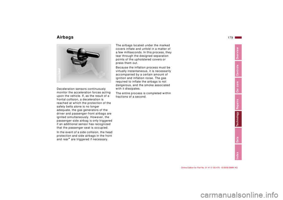
Deceleration sensors continuously
monitor the acceleration forces acting
upon the vehicle. If, as the result of a
frontal collision, a deceleration is
reached at which the protection of the
safety belts alone is no longer
adequate, the gas generators of the
driver and passenger-front airbags are
ignited simultaneously. However, the
passenger-side airbag is only triggered
if an additional sensor has recognized
that the passenger seat is occupied.
In the event of a side collision, the head
protection and side airbags in the front
and rear
* are triggered if necessary.
390de319
The airbags located under the marked
covers inflate and unfold in a matter of
a few milliseconds. In this process, they
tear through the designed separation
points of the upholstered covers or
press them out.
Because the inflation process must be
virtually instantaneous, it is necessarily
accompanied by a certain amount of
ignition and inflation noise. The gas
required to inflate the airbags is not
dangerous, and the smoke associated
with it dissipates.
The entire process is completed within
fractions of a second.
Airbags
Page 180 of 211
180n
ASC+T/DSC
*
Highly sensitive sensors monitor the
number of revolutions of the wheels.
When equipped with DSC, they also
monitor steering angle, lateral accelera-
tion, brake pressure and the movement
of the vehicle around its vertical axis.
If differences in the wheel speeds occur,
ASC+T counteracts the danger of
wheelspin by reducing engine torque; if
necessary, ASC will also respond by
applying the brakes to the rear wheels.
In addition, DSC permanently monitors
the vehicle's current operating condition
and compares it with an ideal condition
that is calculated from the sensor's
signals. If deviations from this occur
(understeering or oversteering, for
instance), DSC can stabilize the vehicle
in fractions of a second by reducing
engine output and with the assistance of
braking intervention at individual
wheels. As a result, dangerous skids can
be prevented even as they are just
beginning, but only within the laws of
physics.
You may need some time to become
accustomed to this system's interven-
tion. However, it provides optimum
drive force and driving stability.
The braking intervention may be
accompanied by sounds specific to the
system.