rear lamp BMW 323i 1996 E36 User Guide
[x] Cancel search | Manufacturer: BMW, Model Year: 1996, Model line: 323i, Model: BMW 323i 1996 E36Pages: 759
Page 187 of 759
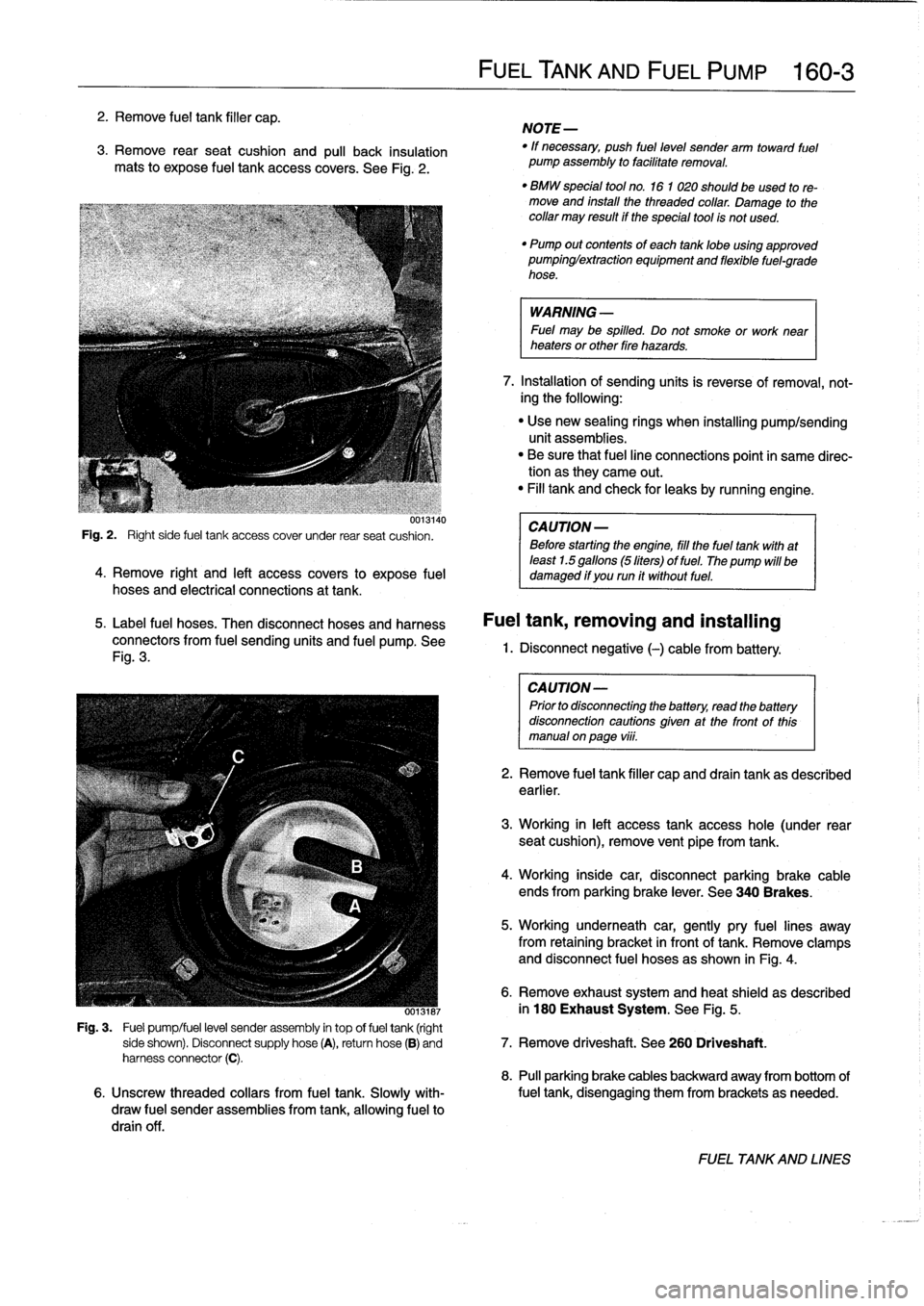
2
.
Remove
fuel
tank
filler
cap
.
3
.
Remove
rearseat
cushion
and
pull
back
insulation
mats
to
expose
fuel
tank
access
covers
.
See
Fig
.
2
.
uui3140
Fig
.
2
.
Right
side
fuel
tank
access
cover
under
rear
seat
cushion
.
4
.
Remove
right
and
left
access
covers
to
expose
fuel
hoses
and
electrical
connections
at
tank
.
5
.
Label
fuel
hoses
.
Then
disconnect
hoses
and
harness
connectors
from
fuel
sending
units
and
fuel
pump
.
See
Fig
.
3
.
FUELTANK
AND
FUEL
PUMP
160-
3
NOTE-
"
If
necessary,
push
fuel
level
sender
arm
toward
fuel
pump
assembly
to
facilitate
removal
.
"
BMW
special
tool
no
.
16
1
020
should
beused
tore-
move
and
install
the
threaded
collar
.
Damage
to
thecollar
may
result
if
the
special
tool
is
not
used
.
"
Pump
out
contents
of
each
tanklobe
using
approved
pumpinglextraction
equipment
and
flexible
fuel-grade
hose
.
WARNING
-
Fuel
may
be
spilled
.
Do
not
smoke
or
work
near
heaters
or
other
fire
hazards
.
7
.
Installation
of
sending
units
is
reverse
of
removal,
not-
ing
the
following
:
"
Use
new
sealing
rings
when
installing
pump/sending
unit
assemblies
.
"
Be
sure
that
fuel
line
connections
point
in
same
direc-tion
as
they
carne
out
.
"
Fill
tank
and
check
for
leaks
by
running
engine
.
CA
UTION-
Before
starting
the
engine,
fill
the
fuel
tank
with
at
least
1.5
gallons
(5liters)
of
fuel
.
The
pump
will
be
damaged
if
you
run
it
without
fuel
.
Fuel
tank,
removing
and
installing
1.
Disconnect
negative
(-)cablefrom
battery
:
CAUTION-
Prior
to
disconnectiog
the
battery,
read
the
battery
disconnection
cautions
given
at
the
front
of
this
manual
onpage
viii
.
2
.
Remove
fuel
tank
filler
capand
drain
tank
as
described
earlier
.
3
.
Working
in
left
access
tank
access
hole
(under
rear
seat
cushion),
remove
vent
pipe
fromtank
.
4
.
Working
inside
car,
disconnectparking
brake
cable
ends
from
parking
brake
lever
.
See
340
Brakes
.
5
.
Working
underneath
car,
gently
pry
fuel
lines
away
from
retaining
bracket
in
front
of
tank
.
Remove
clamps
and
disconnect
fuel
hoses
as
shown
in
Fig
.
4
.
6
.
Remove
exhaust
system
and
heat
shield
as
described
ooisiai
in
180
Exhaust
System
.
See
Fig
.
5
.
Fig
.
3
.
Fuel
pump/fuel
level
sender
assembly
in
top
offuel
tank
(right
side
shown)
.
Disconnect
supply
hose
(A),
return
hose
(B)
and
7
.
Remove
driveshaft
.
See
260
Driveshaft
.
harness
connector
(C)
.
8
.
Pull
parking
brake
cables
backward
away
from
bottom
of
6
.
Unscrew
threaded
collars
from
fuel
tank
.
Slowly
with-
fuel
tank,
disengaging
them
from
brackets
as
needed
.
draw
fuel
sender
assemblies
from
tank,allowing
fuel
to
drain
off
.
FUEL
TANKAND
LINES
Page 188 of 759
160-
4
FUEL
TANK
AND
FUEL
PUMP
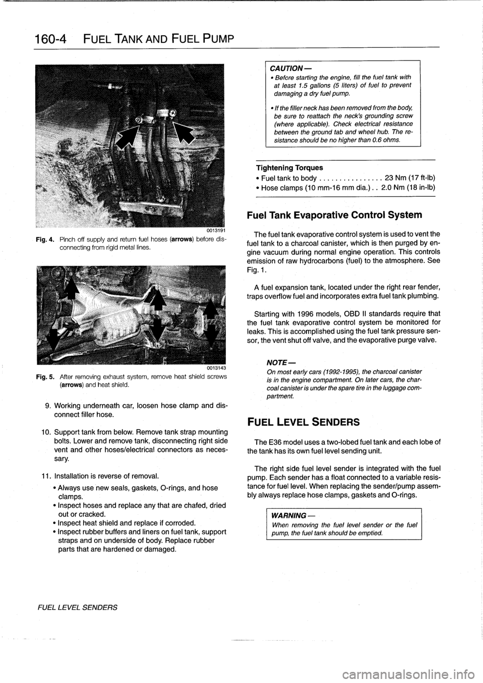
Fig
.
4
.
Pinch
off
supply
and
retum
fuel
hoses
(arrows)
before
dis-
connecting
from
rigid
metal
lines
.
0013143
Fig
.
5
.
After
removing
exhaustsystem,
remove
heat
shield
screws
(arrows)
and
heat
shield
.
9
.
Working
underneath
car,
loosen
hose
clamp
and
dis-
connect
filler
hose
.
10
.
Support
tank
from
below
.
Remove
tank
strap
mounting
bolts
.
Lower
and
remove
tank,
disconnecting
right
side
TheE36
model
uses
a
two-lobed
fuel
tank
and
each
lobeof
vent
and
other
hoses/electrical
connectors
as
neces-
the
tank
has
its
own
fuel
level
sending
unit
.
sary
.
11
.
Installation
is
reverse
of
removal
.
"
Always
use
new
seals,
gaskets,
O-rings,
and
hose
clamps
.
"
Inspect
hoses
and
replace
any
that
are
chafed,
dried
outor
cracked
.
"
Inspect
heat
shield
and
replace
if
corroded
.
"
Inspect
rubber
buffers
and
liners
on
fuel
tank,
support
straps
and
on
underside
of
body
.
Replace
rubber
parts
that
are
hardened
or
damaged
.
FUEL
LEVEL
SENDERS
CAUTION-
"
Before
starting
the
engine,
fill
the
fuel
tank
with
at
least
1.5
gallons
(5
liters)
of
fuel
to
prevent
damaging
a
dry
fuel
pump
.
"
If
the
filler
neck
has
been
removed
from
the
body,
be
sure
toreattach
theneck's
grounding
screw
(where
applicable)
.
Check
electrical
resistance
between
the
ground
tab
and
wheel
hub
.
The
re-
sistance
shouldbeno
higher
than
0
.6
ohms
.
Tightening
Torques
"
Fuel
tank
to
body
.............
...
23
Nm
(17
ft-Ib)
"
Hose
clamps
(10
mm-16
mm
día
.)
..
2
.0
Nm
(18
in-lb)
Fuel
Tank
Evaporative
Control
System
The
fuel
tank
evaporative
control
system
is
used
to
vent
the
fuel
tank
to
a
charcoal
canister,
which
is
then
purgedby
en-
gine
vacuum
during
normal
engine
operatíon
.
This
controls
emission
of
raw
hydrocarbons
(fuel)
to
the
atmosphere
.
See
Fig
.
1
.
A
fuel
expansion
tank,
located
under
the
right
rear
fender,
traps
overflow
fuel
and
incorporates
extra
fuel
tank
plumbing
.
Startingwith
1996
models,
OBD
II
standards
require
that
the
fuel
tank
evaporative
control
system
be
monitored
for
leaks
.
This
is
accomplished
usingthe
fuel
tankpressuresen-
sor,
the
ventshut
off
valve,
and
the
evaporative
purge
valve
.
NOTE-
On
most
early
cars(1992-1995),
the
charcoal
canister
is
in
the
engine
compartment
.
On
latercars,
the
char-
coal
canister
is
under
the
spare
tire
in
the
luggage
com-
partment
.
FUEL
LEVEL
SENDERS
The
right
side
fuel
leve¡
sender
is
integrated
with
the
fuel
pump
.
Each
senderhas
a
float
connected
to
a
variable
resis-
tance
for
fuel
leve¡
.
When
replacing
the
sender/pump
assem-
bly
always
replace
hose
clamps,gaskets
and
O-rings
.
WARNING
-
When
removing
the
fuel
level
sender
or
the
fuel
pump,
the
fuel
tank
should
be
emptied
.
Page 196 of 759
170-2
RADIATOR
AND
COOLING
SYSTEM
Cooling
Fans
TROUBLESHOOTING
Belt-driven
coolingfan
.
The
primary
cooling
fan
is
belt-
driven
.
It
is
mounted
to
the
frontof
the
coolant
pump
through
a
fan
clutch
.
The
fan
clutch
is
a
viscous
fluid
coupling
that
con-
trols
the
speed
of
thefan
based
on
engine
compartment
tem-
perature
.
Electric
cooling
fan
.
Models
with
M44
engine
and
stan-
dard
transmission
substitute
an
electric
fan
for
the
belt-driven
viscous
fan
.
This
is
attached
to
the
rear
of
the
radiator
and
controlledvia
the
DME
5
.2
engine
management
system
.
NOTE-
The
electric
cooling
fan
in
these
models
is
activated
by
the
engine
control
module
(ECM)
.
Auxiliary
coolingfan
.
In
al¡
models
a
two-speed
electric
auxiliary
cooling
fan
is
mounted
behind
the
front
grill
and
in
front
of
the
radiator
.
This
fan
is
primarily
used
for
the
A/C
sys-
tem,
but
also
operates
when
the
coolant
temperature
ex-
ceeds
a
predetermined
leve¡
.
Warnings
and
Cautions
The
following
warnings
and
Cautions
should
beobserved
when
working
on
the
cooling
system
.
WARNING
-
"
Atnormal
operating
temperature
the
cooling
sys-
tem
is
pressurized
.
Allow
the
system
to
cool
as
long
as
possible
before
opening-a
minimum
of
an
hour-then
release
the
cap
slowly
to
allow
sale
release
of
pressure
.
"
Releasing
the
cooling
system
pressure
lowers
the
coolants
boiling
point
and
the
coolant
may
boíl
suddenly
.
Use
heavy
gloves
and
wear
eye
and
laceprotection
to
guard
against
scalding
.
"
Use
extreme
care
when
draining
and
disposing
of
engine
coolant
.
Coolant
is
poisonous
and
lethal
to
humans
and
pets
.
Pets
are
attracted
to
coolant
because
of
its
sweet
smell
and
taste
.
Consult
a
veterinarian
immediately
if
coolant
is
ingested
byan
animal
.
CAUTION-
"
Avoidadding
cold
water
to
the
coolant
while
the
engine
is
hot
or
overheated
.
If
it
is
necessary
to
add
coolant
to
ahot
system,
do
so
only
with
the
engine
running
and
coolant
pump
tuming
.
"
Prior
to
disconnecting
the
battery,
read
the
bat-
tery
disconnection
cautions
given
at
the
front
of
this
manual
on
page
viii
.
TROUBLESHOOTING
Most
cooling
system
faults
can
be
grouped
into
one
of
three
categories
:
"
Cooling
system
leaks
"
Poor
coolant
circulation
"
Radiator
cooling
fan
faults
When
investigating
the
cause
of
overheating
or
coolant
loss,
begin
with
a
visual
inspection
.
Be
sure
to
check
the
con-
dition
and
tension
of
the
coolant
pump
drive
belt
.
Check
hoses
for
cracks
or
softness
.
Check
clamps
for
looseness
.
Check
the
coolant
leve¡
and
check
for
evidence
of
coolantleaks
from
the
engine
.
Check
that
the
radiator
fins
are
not
blocked
with
dirt
or
de-
bris
.
Clean
the
radiator
using
low-pressure
water
or
com-
pressed
air
.
Blow
outward,
fromthe
engine
side
out
.
Inspect
the
coolant
pump
by
first
removing
the
drive
belt
from
the
pump
.
Firmly
grasp
opposite
sídes
of
the
pulley
and
check
for
play
in
all
directions
.
Spin
the
pulley
and
check
that
the
shaft
runs
smoothly
.
NOTE-
The
coolant
provides
lubrication
for
the
pump
shaft,
soan
occasional
drop
of
coolant
leaking
from
the
pump
is
acceptable
.
If
coolant
drips
steadily
from
the
vent
hole,
the
pump
should
be
replaced
.
The
cooling
system
becomes
pressurized
at
normal
operat-
ing
temperature,
which
raises
the
boiling
point
of
the
coolant
.
Leaks
may
prevent
the
system
from
becoming
pressurized,
allowing
the
coolant
to
boil
at
a
lower
temperature
.
If
visual
ev-
idence
is
inconclusive,
a
cooling
system
pressure
test
can
help
to
pinpointhard-to-find
leaks
.
If
the
cooling
system
is
full
of
coolant
and
holds
pressure,
the
next
most
probable
cause
of
overheating
are
:
"
Faulty
radiator
fan
"
Loose
or
worn
drive
belt
"
Failed
thermostat
or
coolant
pump
"
Clogged/plugged
radiator
or
coolant
passages
.
NOTE
-
"
Some
early
style
coolant
pumps
were
fitted
wíth
fi-
berlplastic
type
impellers
.
Over
time,
this
impeller
can
wear
away
and
result
in
overheating
.
The
plastic
im-
peller
can
also
slip
or
free-wheel
on
the
pump
shaft
.
If
the
engine
overheats
and
no
other
faults
canbe
found,
theold
style
impeller
may
be
the
cause
of
the
problem
.
"
Only
pumps
with
the
updated
metal
impeller
should
be
used
for
replacement
.
Page 207 of 759
GENERAL
.
.
.......
.
......
.
...
.
.
.
.
.
...
180-1
Exhaust
system,
removing
and
installing
.
...
.180-3
EXHAUST
SYSTEM
REPLACEMENT
.
...
180-1
Exhaust
manifolds,
removing
and
installing
.
.
.180-5
GENERAL
The
exhaust
system
is
designed
to
be
maintenance
free,
al-
though
regular
inspection
is
warranted
due
to
the
harsh
oper-
atingconditions
.
Under
normal
conditions,
the
catalytic
converter
does
not
require
replacement
unless
it
is
damaged
.
On
1996
and
later
cars,
a
pre-
and
post-catalytic
converter
oxygen
sensor
is
used
at
each
catalytic
converter
.
Be
sure
to
take
care
when
removingthe
system
not
to
damage
the
sen-
EXHAUST
SYSTEMREPLACEMENT
sors
.
See
130
Fuel
Injection
for
information
on
testing
oxygen
sensors
.
NOTE-
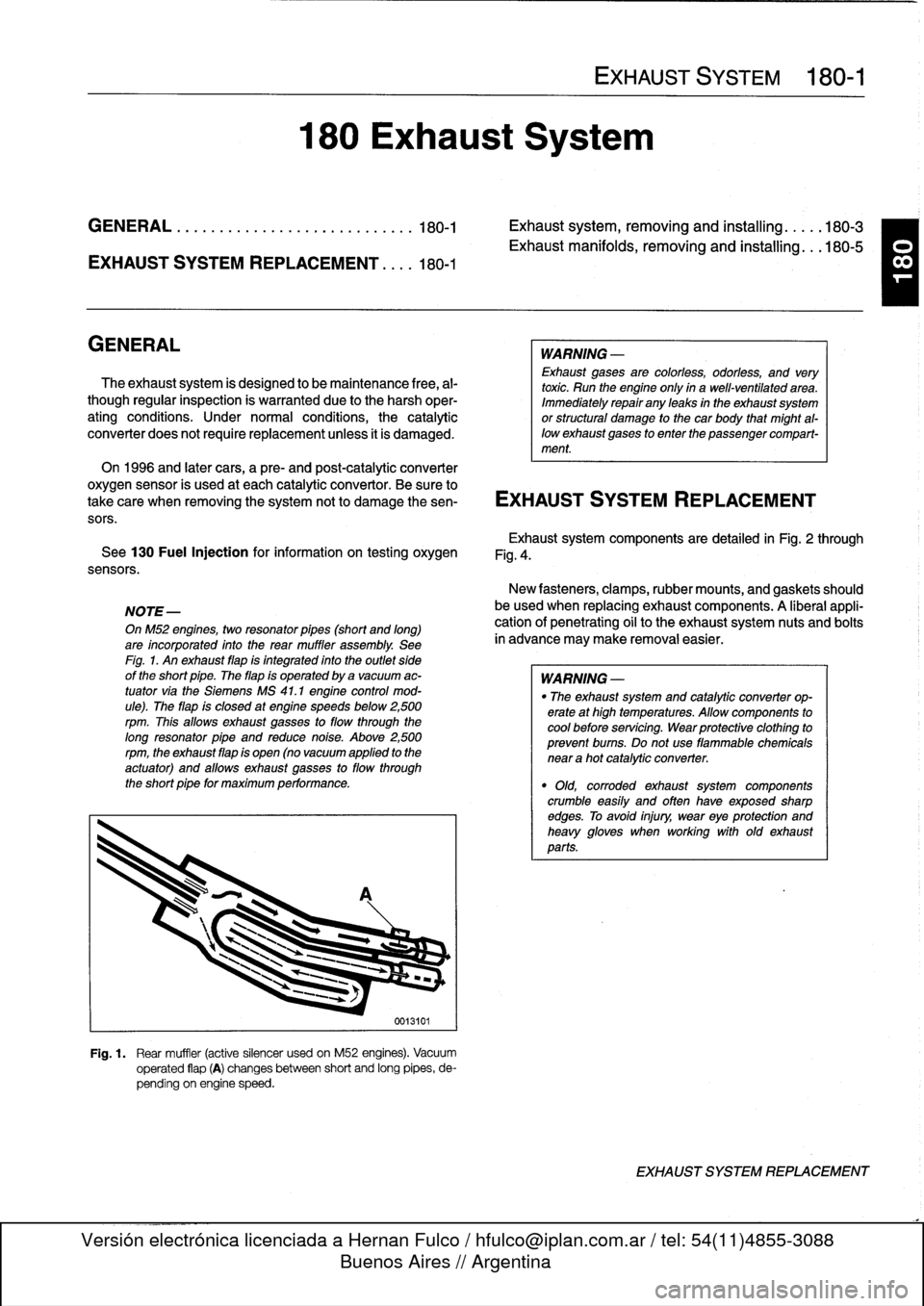
OnM52
engines,
two
resonator
pípes
(short
and
long)
are
incorporated
into
the
rear
muffler
assembly
.
See
Fíg
.
1
.
An
exhaust
flap
is
integrated
into
the
outlet
side
of
the
short
pipe
.
The
flap
is
operated
by
a
vacuum
ac-
tuator
via
the
Siemens
MS
41
.1
engine
control
mod-
ule)
.
The
flap
is
closed
at
engine
speeds
below
2,500
rpm
.
This
allows
exhaust
gasses
to
flow
through
the
long
resonator
pipe
and
reduce
noise
.
Above
2,500rpm,
the
exhaust
flap
is
open
(no
vacuum
applied
to
the
actuator)
and
allows
exhaust
gasses
to
flow
through
the
short
pipe
for
maximum
performance
.
180
Exhaust
System
0013101
Fig
.
1
.
Rear
muffler
(active
silencer
usedon
M52
engines)
.
Vacuum
operated
flap
(A)
changesbetween
short
and
long
pipes,
de-
pending
on
engine
speed
.
EXHAUST
SYSTEM
180-1
WARNING
-
Exhaust
gases
are
colorless,
odorless,
and
very
toxic
.
Run
the
engine
only
ín
a
well-ventilated
area
.
Immediately
repair
any
leaks
in
the
exhaust
system
or
structural
damage
to
the
car
body
that
might
al-
lowexhaust
gases
to
enter
the
passenger
compart-
ment
.
Exhaustsystem
components
are
detailed
in
Fig
.
2
through
Fig
.
4
.
New
fasteners,
clamps,rubber
mounts,
and
gaskets
should
be
used
when
replacing
exhaust
components
.
A
liberal
appli-
cationof
penetrating
oil
to
the
exhaustsystem
nuts
and
bolts
in
advance
may
make
removal
easier
.
WARNING
-
"
The
exhaust
system
and
catalytic
converter
op-
erate
at
high
temperatures
.
Allow
components
to
cool
before
servicing
.
Wear
protectíve
clothíng
to
prevent
bums
.
Do
not
use
flammable
chemicals
near
a
hot
catalytic
converter
.
"
Old,
corroded
exhaust
system
components
crumble
easíly
and
often
have
exposed
sharp
edges
.
To
avoid
injury,
wear
eye
protection
and
heavy
gloves
when
working
with
old
exhaust
parts
.
EXHAUST
SYSTEM
REPLACEMENT
T
Page 208 of 759
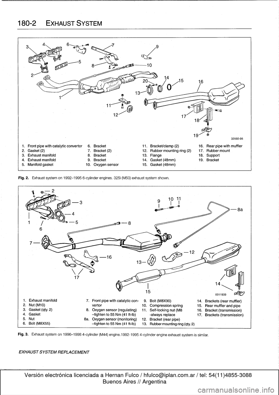
180-2
EXHAUST
SYSTEM
a
EXHAUST
SYSTEM
REPLACEMENT
Fig
.
2
.
Exhaust
systemon
1992-1995
6-cylinder
engines
.
3251
(M50)
exhaust
system
shown
.
E~
)l-,malo
m~=
i
32592-95
1
.
Front
pipe
with
catalytic
convertor
6
.
Bracket
11
.
Bracket/clamp
(2)
16
.
Rear
pipewith
muffler
2
.
Gasket
(2)
7
.
Bracket
(2)
12
.
Rubber
mounting
ring
(2)
17
.
Rubber
mount
3
.
Exhaust
manifold
8
.
Bracket
13
.
Flange
18
.
Support4
.
Exhaust
manifold
9
.
Bracket
14
.
Gasket
(48mm)
19
.
Bracket
5
.
Manifold
gasket
10
.
Oxygen
sensor
15
.
Gasket
(48mm)
eme°"
k
:I>
-
8a
1
.
Exhaust
manifold
7
.
Front
pipe
with
catalytic
con-
9
.
Bolt
(M8X90)
14
.
Brackets
(rear
muffier)
2
.
Nut
(M10)
vertor
10
.
Compression
spring
15
.
Rear
muffler
and
pipe
3
.
Gasket
(clty
.
2)
8
.
Oxygen
sensor
(regulating)
11
.
Self-lockingnut
(M8
16
.
Bracket
(transmission)
4
.
Gasket
-tightento
55
Nm
(41
ft-Ib)
-always
replace
17
.
Brackets
(transmission)
5
.
Nut
8a
.
Oxygen
sensor
(monitoring)
12
.
Bracket
(rear
pipe)
6
.
Bolt
(M8X55)
-tightento
55
Nm
(41
ft-Ib)
13
.
Rubber
mounting
ring
(9ty
2)
Fig
.
3
.
Exhaust
systemon
1996-1998
4-cylinder
(M44)
engine
.1992-1995
4-cylinder
engine
exhaust
system
is
similar
.
Page 210 of 759
180-
4
EXHAUST
SYSTEM
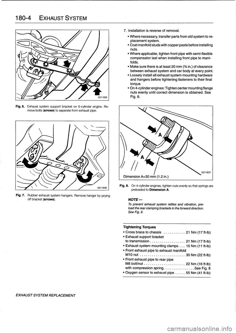
Fig
.
6
.
Exhaust
system
support
bracket
on
6-cylinder
engine
.
Re-
move
bolts
(arrows)
to
separate
from
exhaust
pipe
.
Fig
.
7
.
Rubber
exhaust
system
hangers
.
Remove
hanger
by
prying
off
bracket
(arrows)
.
EXHAUST
SYSTEM
REPLACEMENT
7
.
Installation
is
reverse
of
removal
.
"
Where
necessary,
transfer
parts
from
old
system
to
re-
placement
system
.
"
Coat
manifold
studs
with
copper
paste
before
installing
nuts
.
"
Where
applicable,
tighten
front
pípewith
semi-flexible
compensator
last
when
installing
front
pipe
to
mani-
folds
.
"
Make
sure
there
is
at
least
20
mm
(
3
/4
in
.)
of
clearance
between
exhaust
systemand
car
body
at
every
point
.
"
Loosely
install
all
exhaust
system
mountinghardware
and
hangers
before
tightening
fasteners
to
their
final
torque
.
"
On
4-cylinder
engines
:
Tighten
center
mounting
flange
nuts
evenly
until
correct
dimension
is
obtained
.
See
Fig
.
8
.
ri
J%JJ
w
~~~JJJJ
1
Fig
.
8
.
On
4-cylinder
engines,
tighten
nuts
evenly
so
that
spríngs
are
preloaded
to
Dimension
A
.
NOTE-
To
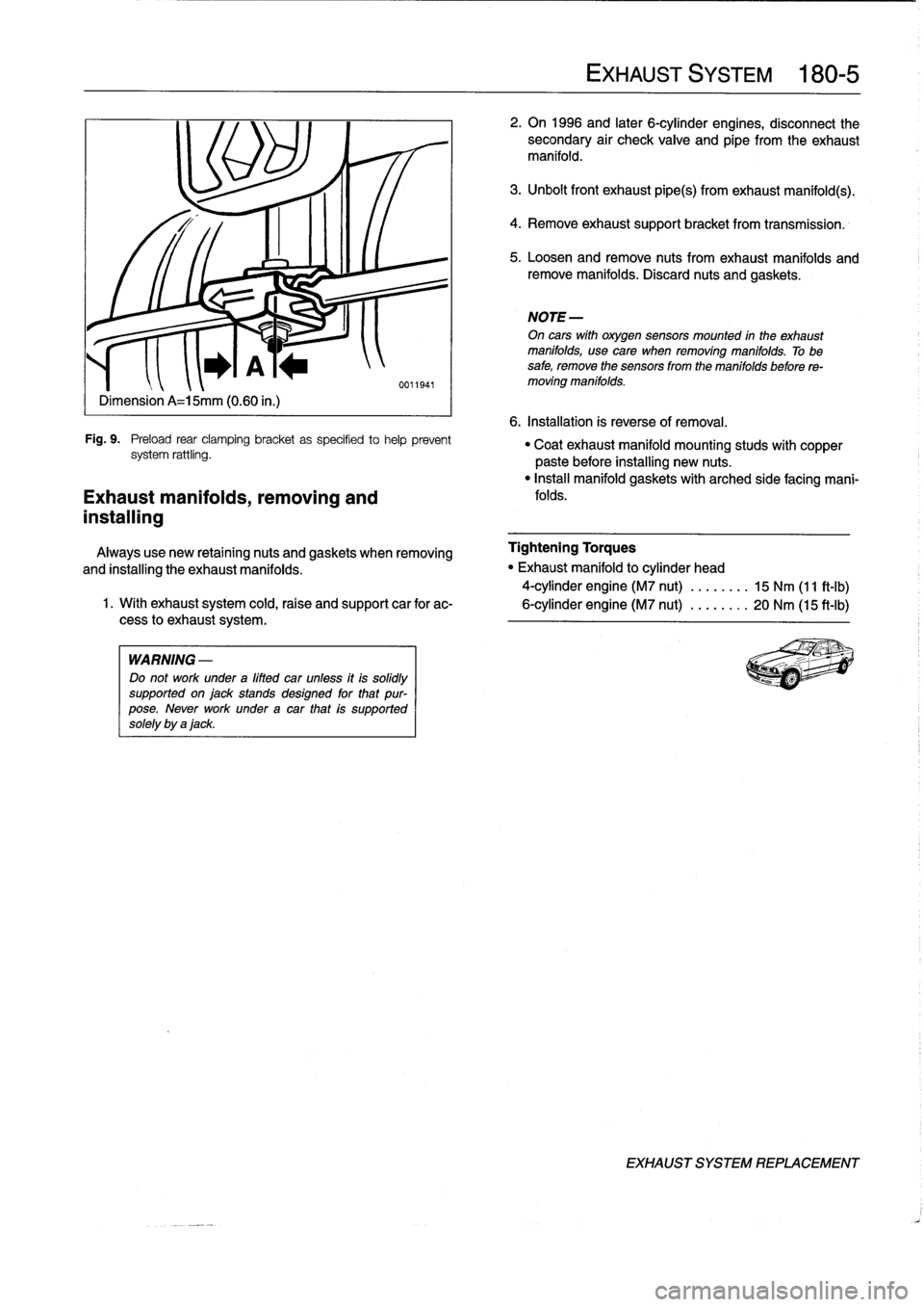
prevent
exhaust
system
rattles
and
vibration,
pre-load
the
rear
clamping
brackets
in
the
íonaard
direction
.
See
Fig
.
9
.
0011937
Tightening
Torques
"
Cross
brace
to
chassis
..
.
...
.
..
..
21
Nm
(17
ft-Ib)
"
Exhaust
support
bracket
to
transmission
.
.
.
.
.......
.....,.
21
Nm
(17
ft-Ib)
"
Exhaust
system
mounting
clamps
...
15
Nm
(11
ft-Ib)
"
Front
exhaust
pipeto
exhaust
manifold
M10
nut
.
.
.
...
.
..
..............
30
Nm
(22
ft-Ib)
"
Front
exhaust
pipe
torear
pipe
M8
bolt/nut
..
....
.
..............
22
Nm
(16
ft-Ib)
with
compression
spring
................
See
Fig
.
8
"
Oxygen
sensor
to
exhaust
pipe
.....
55
Nm
(41
ft-Ib)
Page 211 of 759
Dimension
A=15mm
(0
.60
in
.)
Fig
.
9
.
Preload
rear
clamping
bracket
as
specifíed
tohelp
prevent
system
rattling
.
Exhaust
manifolds,
removing
and
installing
WARNING
-
Do
not
work
under
a
lifted
car
unfess
itis
solidly
supportedonjackstands
designed
for
that
pur-
pose
.
Never
work
underacar
that
is
supported
solely
by
ajack
.
EXHAUST
SYSTEM
180-
5
2
.
On
1996
and
later
6-cylinder
engines,
disconnect
the
secondary
air
check
valve
and
eipe
from
the
exhaust
manifold
.
3
.
Unbolt
front
exhaust
pipe(s)
from
exhaust
manifold(s)
.
4
.
Remove
exhaustsupport
bracket
from
transmission
.
5
.
Loosen
andremove
nuts
fromexhaust
manifolds
and
remove
manifolds
.
Discard
nuts
and
gaskets
.
NOTE-
On
cars
wíth
oxygen
sensors
mounted
in
the
exhaust
manifolds,
usecare
when
removing
manifolds
.
Tobe
safe,
remove
the
sensors
from
the
manifolds
before
re-
moving
manifolds
.
6
.
Installation
is
reverse
of
removal
.
"
Coatexhaust
manifold
mounting
studs
with
copper
paste
before
installing
new
nuts
.
"
Insta¡¡
manifold
gaskets
with
arched
side
facing
mani-
folds
.
Always
use
new
retaining
nuts
and
gaskets
when
removing
Tightening
Torques
and
installing
the
exhaust
manifolds
.
"
Exhaust
manifold
to
cylinder
head
4-cylinder
engine
(M7
nut)
........
15
Nm
(11
ft-Ib)
1
.
With
exhaust
system
cold,raise
and
support
car
for
ac-
6-cylinder
engine
(M7
nut)
........
20
Nm
(15
ft-Ib)
cess
lo
exhaust
system
.
EXHAUST
SYSTEM
REPLACEMENT
Page 231 of 759
2
.
On
MS
270R/A4S
310R
transmissions
:
Remove
front
5
.
Installation
is
reverse
of
Rmoval
.
and
rear
oil
sump
mounting
bolts
andremove
sumps
"
Always
replace
sea¡
for
drain
plug
and
al¡
gasket(s)
andand
sump
gaskets
.
O-rings
.
"
Clean
sump
and
sump
magnet(s)
using
a
lint-free
NOTE-
cloth
.
The
MS
270
R/A4S
310
R
transmissions
may
be
fitted
"
On
MS
270R/A4S310R
transmissions
:
Use
new
bolts
with
ASE
(inch)
bolts
.
at
sump
and
tighten
bolts
in-line,
one
after
other
(do
nottighten
bolts
in
a
cross-wise
pattern)
.
3
.
On
A5S
310Z
transmission
:
Remove
oil
sump
mount-
"
On
MS
310Z
transmission,
be
sureto
instan
rounded
ing
bolts
and
brackets,
noting
position
of
brackets
.
Re-
sump
clamping
brackets
at
corners
of
sump
.
move
"
Fill
transmission
with
approved
fluid
.
sump
and
sump
gasket
.
"
Check
fluid
level
as
described
under
ATF
leve¡,
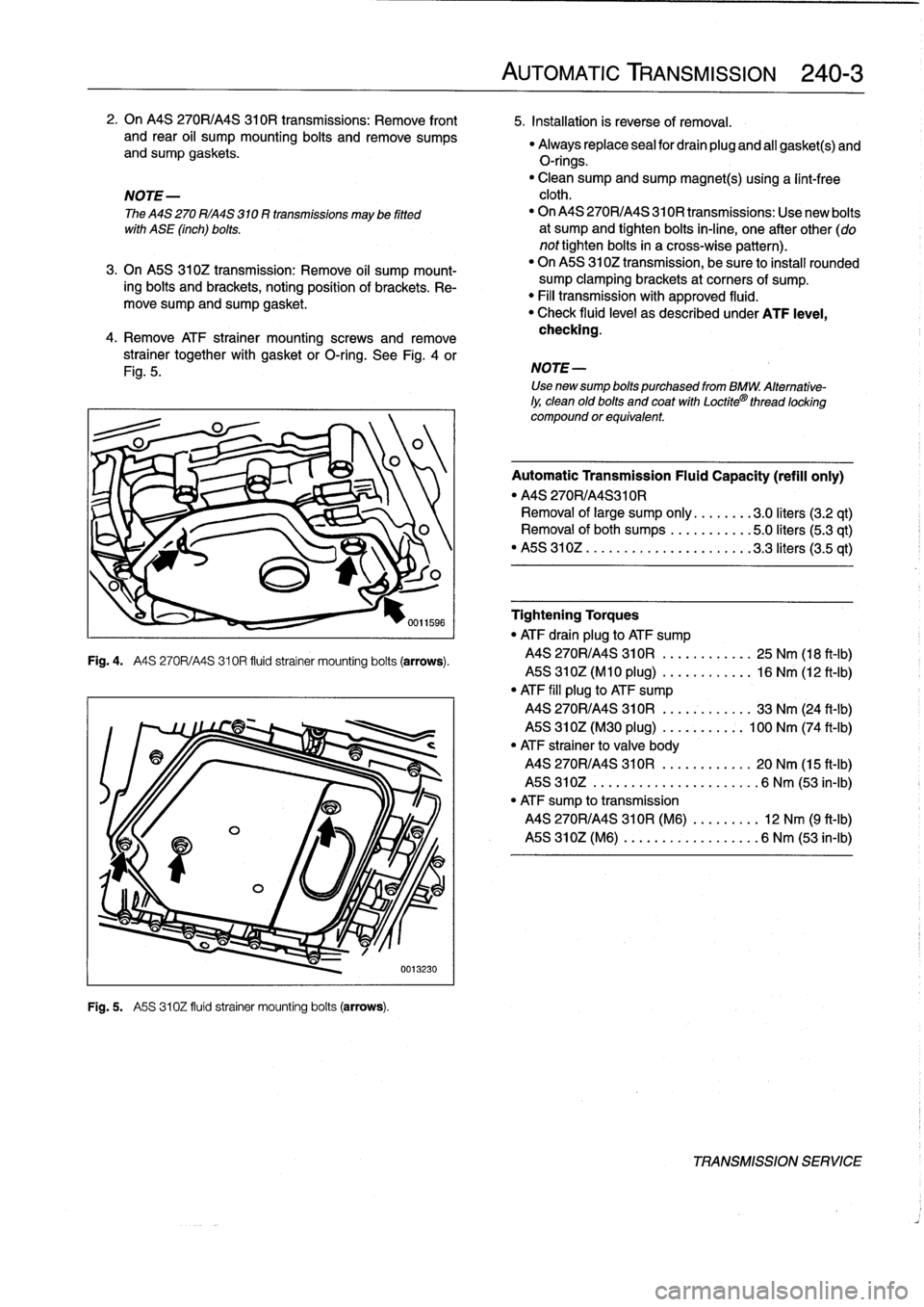
4
.
Remove
ATF
otra¡ner
mount¡ng
screws
and
remove
checking
.
strainer
together
with
gasket
orO-ring
.
See
Fig
.
4
or
Fig
.
5
.
Fig
.
4
.
A4S
270R/A4S310R
fluid
strainer
mounting
boits
(arrows)
.
Fig
.
5
.
A5S
310Z
fluid
strainer
mounting
boits
(arrows)
.
0013230
AUTOMATIC
TRANSMISSION
240-
3
NOTE-
Use
newsump
bolts
purchased
from
BMW
.
Alternative-
ly,
clean
old
bolts
and
coat
with
Loctite®
thread
locking
compound
or
equivalent
Automatic
Transmission
Fluid
Capacity
(refill
only)
"
MS
270R/A4S310R
Removal
of
large
sump
only
........
3
.0liters
(3.2
qt)
Removal
ofboth
sumps
...........
5
.0liters(5
.3
qt)
"
MS
310Z
..
..
..................
3
.3liters
(3.5
qt)
Tightening
Torques
"
ATF
drain
plug
to
ATF
sump
MS
270R/A4S
310R
..........
..
25
Nm
(18
ft-Ib)
MS
310Z(M10
plug)
..........
..
16
Nm
(12
ft-Ib)
"
ATF
fill
plug
to
ATF
sump
MS
270R/A4S
310R
..........
..
33
Nm
(24
ft-Ib)
MS
310Z(M30
plug)
.....
..
..
:.
100
Nm
(74
ft-Ib)
"
ATF
strainer
to
valve
body
MS
270R/A4S
310R
.....
..
.
...
.
20
Nm
(15
ft-Ib)
MS
310Z
..............
..
.
...
..
6
Nm
(53
in-lb)
"
ATF
sump
to
transmission
MS
270R/A4S
310R
(M6)
.
..
.
..
...
12
Nm
(9
ft-¡b)
MS
310Z
(M6)
..........
..
.
..
...
6
Nm
(53
in-¡b)
TRANSMISSION
SERVICE
Page 241 of 759
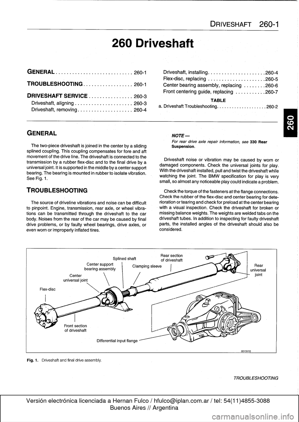
DRIVESHAFT
SERVICE
.
...
.
.
.
...
.
..
.
.
.260-3
Driveshaft,
aligning
...............
.
...
.
.
260-3
Driveshaft,
removing
..............
.
.
.
.
.
.
260-4
260
Driveshaft
DRIVESHAFT
260-1
GENERAL
.
.
.
.
.
.
.
.....
.
.
.
........
.
...
.
260-1
Driveshaft,
installing
.
....
.
..
.
............
260-4
Flex-disc,
replacing
.....
.
.
.
.............
260-5
TROUBLESHOOTING
..
.
.
.
...
.
.........
260-1
Center
bearing
assembly,
replacing
.
......
.260-6
Frontcentering
guide,
replacing
..
.
.......
.
260-7
TABLE
a
.
Driveshaft
Troubleshooting
.
.
...
......
.
....
..
.
.
260-2
GENERAL
NOTE-
For
rear
drive
axlerepair
information,
see330
Rear
The
two-piece
driveshaft
is
joined
in
thecenter
by
a
sliding
Suspension
.
splined
coupling
.
This
coupling
compensates
for
fore
and
aft
movement
of
the
drive
line
.
The
driveshaft
ís
connected
to
the
Driveshaft
noise
or
vibration
may
be
caused
by
worn
or
transmission
bya
rubber
flex-disc
and
to
the
final
drive
by
a
damaged
components
.
Check
the
universal
joints
for
play
.
universal
joint
.
It
is
supported
in
the
micidle
by
a
center
support
With
the
driveshaft
installed,
pull
and
twist
the
driveshaft
while
bearing
.
The
bearing
is
mounted
in
rubber
to
isolate
vibration
.
watching
the
joint
.
The
BMW
specificationfor
play
is
very
See
Fig
.
1
.
small,
so
almost
any
noticeableplay
could
indicate
a
problem
.
TROU
BLESHOOTING
Check
thetorque
of
thefasteners
at
the
flange
connections
.
Check
therubber
of
the
flex-disc
and
center
bearing
for
dete
The
source
of
driveline
vibrations
and
noise
can
be
difficult
rioration
or
tearíng
and
check
for
preload
at
the
center
bearing
to
pinpoint
.
Engine,
transmission,
rear
axle,
or
wheel
vibra-
with
a
visual
inspection
.
Check
the
driveshaft
for
broken
or
tions
can
be
transmitted
through
the
driveshaft
to
the
car
missing
balance
weights
.
The
weights
are
welded
tabs
on
the
body
.
Noises
from
the
rear
of
thecar
may
be
caused
by
final
driveshaft
tubes
.
In
addition
to
inspecting
for
faulty
driveshaft
drive
problems,
orby
faulty
wheel
bearings,
drive
axies,
or
parts,
the
installed
angles
of
the
driveshaft
should
also
be
evenworn
or
improperly
inflatedtires
.
considered
.
Flex-disc
Center
universal
joint
Fig
.1
.
Driveshaft
and
final
drive
assembly
.
Rear
section
Splined
shaft
of
driveshaft
Center
support
`
Clamping
sleeve
bearíng
assembly
Differential
inputflange
0013110
TROUBLESHOOTING
Page 244 of 759
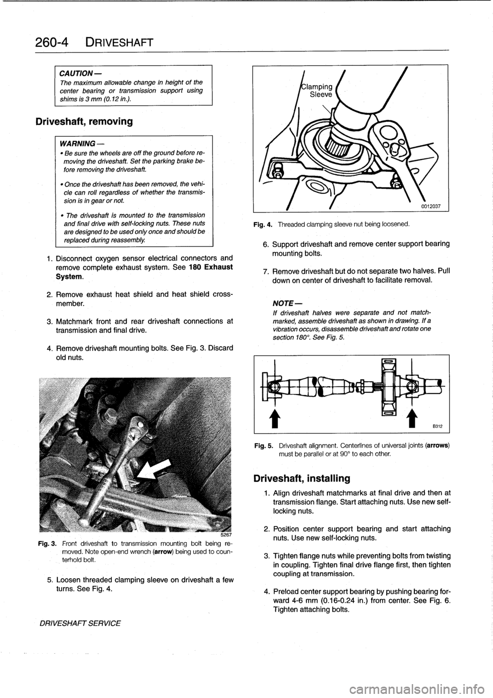
260-
4
DRIVESHAFT
CAUTION
-
The
maximum
allowable
change
in
height
of
the
center
bearing
or
transmission
support
using
shims
is
3
mm
(0
.12
in
.)
.
Driveshaft,
removing
WARNING
-
"
Be
sure
the
wheels
are
off
the
ground
before
re-
moving
the
driveshaft
.
Set
the
parking
brake
be-
fore
removing
the
driveshaft
.
"
Once
the
driveshaft
has
been
removed,
the
vehi-
cle
can
roll
regardless
of
whether
the
transmis-
sion
isin
gear
or
not
.
"
The
driveshaft
fs
mounted
to
thetransmission
and
final
drive
with
self-locking
nuts
.
These
nuts
are
designed
to
be
used
only
once
and
should
be
replaced
during
reassembly
.
1.
Disconnect
oxygen
sensor
electrical
connectors
and
remove
complete
exhaustsystem
.
See
180
Exhaust
System
.
4
.
Remove
driveshaft
mounting
bolts
.
See
Fig
.
3
.
Discard
old
nuts
.
JG
Fig
.
3
.
Front
driveshaft
totransmission
mounting
bolt
being
re-
moved
.
Note
open-end
wrench
(arrow)
being
used
to
coun-
terhold
bolt
.
5
.
Loosen
threaded
clamping
sleeve
on
driveshaft
a
few
tucos
.
See
Fig
.
4
.
DRIVESHAFT
SERVICE
Fig
.
4
.
Threaded
clamping
sleeve
nut
being
loosened
.
0012037
6
.
Support
driveshaft
andremove
center
support
bearing
mounting
bolts
.
7
.
Remove
driveshaft
but
do
not
separate
two
halves
.
Pull
down
on
center
of
driveshaft
to
facilitate
removal
.
2
.
Remove
exhaust
heat
shield
and
heat
shieldcross-
member
.
NOTE-
If
driveshaft
halves
were
separate
and
not
match-
3
.
Matchmark
front
and
rear
driveshaft
connections
at
marked,
assemble
driveshaft
as
shown
in
drawing
.
If
a
transmissíon
and
final
drive
.
vibration
occurs,
disassemble
driveshaftand
rotate
one
section
180°
.
See
Fig
.
5
.
Driveshaft,
installing
Fig
.
5
.
Driveshaft
alignment
.
Centerlinesof
universal
joints
(arrows)
must
be
parallel
or
at
90°
to
each
other
1
.
Align
driveshaft
matchmarks
at
final
drive
and
then
at
transmission
flange
.
Start
attaching
nuts
.
Use
new
self-
locking
nuts
.
2
.
Position
center
support
bearing
and
start
attaching
nuts
.
Use
new
self-locking
nuts
.
3
.
Tighten
flangenuts
while
preventing
bolts
from
twisting
in
coupling
.
Tighten
final
drive
flange
first,
then
tighten
coupling
at
transmission
.
4
.
Preload
center
support
bearing
by
pushing
bearing
for-
ward4-6
mm
(0
.16-0
.24
in
.)
from
center
.
See
Fig
.
6
.
Tighten
attaching
bolts
.