rear lamp BMW 323i 1996 E36 Owner's Manual
[x] Cancel search | Manufacturer: BMW, Model Year: 1996, Model line: 323i, Model: BMW 323i 1996 E36Pages: 759
Page 245 of 759
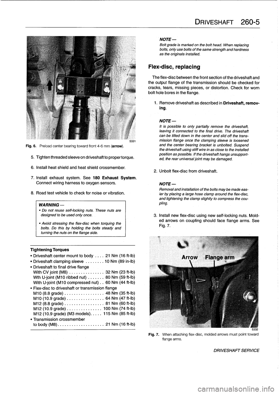
Fig
.
6
.
Preload
center
bearing
toward
front
4-6
mm
(arrow)
.
5331
5
.
Tightenthreadedsleeveondriveshafttopropertorque
.
6
.
Insta¡¡
heat
shield
and
heat
shield
crossmember
.
Tightening
Torques
"
Driveshaftcenter
mount
to
body
.
.
..
21
Nm
(16
ft-Ib)
"
Driveshaft
clamping
sleeve
.....
.
.
.
10
Nm
(89
in-lb)
"
Driveshaft
to
final
drive
flange
With
CV
joint
(M8)
............
...
32
Nm
(23
ft-Ib)
Wth
U-joint
(M10
ribbed
nut)
....
...
80
Nm
(59
ft-Ib)
With
U-joint
(M10
compressed
nut)
..
60
Nm
(44
ft-Ib)
"
Flex-disc
to
driveshaft
or
transmissionflange
M10
(8.8
grade)
.........
.
....
..
.
48
Nm
(35
ft-Ib)
M10
(10
.9
grade)
........
.
....
...
64
Nm
(47
ft-Ib)
M12
(8.8
grade)
........
.....
..
.
.
81
Nm
(60
ft-Ib)
M12
(10
.9
grade)
.
.
....
......
...
100
Nm
(74
ft-Ib)
M12
(10
.9
grade)
(M3
models)
..
.
.
.
115
Nm
(85
ft-Ib)
"
Transmission
crossmember
to
body
(M8)
.
....
...........
....
21
Nm
(16
ft-Ib)
NOTE-
Bolt
grade
is
markedon
the
bolt
head
.
When
replacing
bolts,
only
use
bolts
of
the
same
strength
and
hardnessas
the
originalsinstalled
.
Flex-disc,
replacing
The
flex-disc
between
the
front
section
of
the
driveshaft
and
theoutputflange
of
the
transmission
should
be
checked
for
cracks,
tears,
missing
pieces,
or
distortion
.
Check
for
worn
bolt
hole
bores
in
theflange
.
1
.
Remove
driveshaft
as
described
in
Driveshaft,
remov-
ing
.
NOTE-
¡t
is
possible
to
only
partially
remove
the
driveshaft,
leaving
it
connected
to
the
final
drive
.
The
driveshaft
canbe
tilted
down
in
thecenter
and
slidoff
the
trans-
mission
flange
once
the
clamping
sleeve
is
loosened
and
the
center
bearing
bracket
is
unbolted
.
Suspend
the
driveshaft
using
stiff
wire
in
as
close
to
the
installed
position
as
possible
.
If
the
driveshaft
hangs
unsupport-
ed,
the
rear
universal
joint
may
be
damaged
.
2
.
Unbolt
flex-dísc
from
driveshaft
.
DRIVESHAFT
260-
5
7
.
Install
exhaust
system
.
See
180
Exhaust
System
.
Connect
wiring
harness
to
oxygen
sensors
.
NOTE-
Removaland
installation
of
the
boltsmaybe
made
eas-
8
.
Road
test
vehicle
to
check
for
noiseor
vibration
.
ier
by
placing
a
large
hose
clamp
around
the
flex-disc,
and
tightening
the
clamp
slightlyto
compress
the
cou
WARNING
-
pling
.
"
Do
not
reuse
self-locking
nuts
.
These
nuts
aredesigned
to
beused
only
once
.
3
.
Insta¡¡
new
flex-disc
using
new
self-locking
nuts
.
Mold-
"
Avóid
stressing
the
flex-disc
when
torquing
the
ed
arrows
on
coupling
should
face
flange
arms
.
See
bolts
Do
this
holding
the
bolts
Fig
.
7
.
steady
and
.
uy
turning
the
nuts
on
theflange
side
.
5
:132
Fig
.
7
.
When
attaching
flex-disc,
molded
arrows
must
point
toward
flange
arms
.
DRIVESHAFT
SERVICE
Page 246 of 759
260-
6
DRIVESHAFT
4
.
Insta¡¡
driveshaft
as
described
in
Driveshaft,
install-
ing
.
Tightening
Torques
"
Driveshaft
center
mount
to
body
.
...
21
Nm
(16
ft-Ib)
"
Driveshaft
clamping
sleeve
.....
...
10
Nm
(89
in-lb)
"
Driveshaft
to
final
drive
flange
With
CV
joint
(M8)
............
...
32
Nm
(23
ft-Ib)
Wth
U-joint
(M10
ribbed
nut)
......
.
80
Nm
(59
ft-Ib)
With
U-joint
(M10
compressed
nut)
.
.
60
Nm
(44
ft-Ib)
"
Flex-disc
to
driveshaft
or
transmission
flange
M10
(8
.8
grade)
.
...
.............
48
Nm
(35
ft-Ib)
M10
(10
.9
grade
.
...
.............
64
Nm
(47
ft-Ib)
M12
(8
.8
grade)
..
..
.............
81
Nm
(60
ft-Ib)
M12
(10
.9
grade)
.
..
............
100
Nm
(74
ft-Ib)
M12
(10
.9
grade)
(M3
models)
.....
115
Nm
(85
ft-Ib)
"
Transmission
crossmember
to
body
(M8)
......
...
.
..
........
21
Nm
(16
ft-Ib)
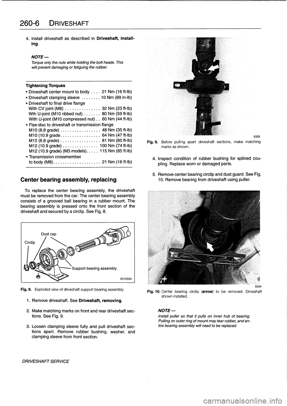
5
.
Remove
center
bearing
circlip
and
dust
guard
.
See
Fig
.
Center
bearing
assembly,
replacing
10
.
Remove
bearing
from
driveshaft
using
puller
.
To
replace
thecenter
bearing
assembly,
the
driveshaft
must
be
removed
from
thecar
.
The
center
bearing
assembly
consists
of
a
grooved
ball
bearing
in
a
rubber
mount
.
The
bearing
assembly
is
pressed
onto
the
front
section
of
the
driveshaft
and
securedby
a
circlip
.
See
Fig
.
8
.
Circlip
NOTE
-
Torque
only
the
nuts
while
holding
the
bolt
heads
.
Thís
will
prevent
damaging
or
fatiguing
the
rubber
.
Dust
cap
Fig
.
8
.
Exploded
view
of
driveshaft
support
bearing
assembly
.
1
.
Remove
driveshaft
.
See
Driveshaft,
removing
.
DRIVESHAFT
SERVICE
0012594
5333
Fig
.
9
.
Before
pulling
apart
driveshaft
sections,
make
matching
marks
as
shown
.
4
.
Inspect
condition
of
rubber
bushing
for
splined
cou-
pling
.
Replace
worn
or
damaged
parts
.
2
.
Make
matching
marks
on
front
and
rear
driveshaft
sec-
NOTE-
tions
.
See
Fig
.
9
.
Install
puller
so
that
it
pulls
on
inner
hub
of
bearing
.
Pulling
on
outer
ring
of
mount
may
tear
rubber,
and
en
3
.
Loosen
clamping
sleeve
fully
and
pull
driveshaft
sec-
tire
bearing
assembly
will
need
to
be
replaced
.
tions
apart
.
Remove
rubber
bushing,
washer,
and
clamping
sleeve
from
front
section
.
5334
Fig
.
10
.
Center
bearing
circlip
(arrow)
to
be
removed
.
Driveshafl
shown
installed
.
Page 249 of 759
SUSPENSION,
STEERING
ANDBRAKES-GENERAL
300-1
300
Suspension,
Steering
and
Brakes-General
GENERAL
.....
.
....
.
.....
.
.
.
........
.300-1
M3
SUSPENSION
AND
BRAKES
.......
.
...
300-7
Front
Suspension
..........
.
.
.
...
.
.....
300-1
Steering
...
.
.
.
.
.
....
.
.
.
...
.
.
.
...
.
...
.
.
300-2
SUSPENSION
AND
STEERING
Rear
Suspension
....
.
.
.
...
.
.
.
...
.
.....
300-2
TROUBLESHOOTING
..
.
.
.
.............
300-7
Brakes
.
.
.
.
.
.
.
.
....
.
...........
.
.
.
.
.
.
300-2
Tires
and
wheeis
.
................
.
.
.
.
.
.
300-2
TABLE
a
.
AST
Indicator
Lamp
Function
..
..
.
..
.
.........
300-5
INTEGRATED
SYSTEMS
.........
.
.
.
.
.
.
300-2
b
.
Suspension
and
Steering
Troubleshooting
......
.300-8
Antilock
Brake
System
(ABS)
.......
.
.
.
.
.
.
300-2
Al¡
Season
Traction
(AST)
.........
.
.
.
.
.
.
300-4
GENERAL
Front
Suspension
This
section
covers
general
information
for
front
and
rear
The
lower
control
arms
connect
the
front
suspension
struts
suspension,
the
steering
system,
and
the
brakíng
and
traction
to
mounting
points
on
the
subframe
crossmember
and
the
control
systems
.
body
.
See
Fig
.
2
.
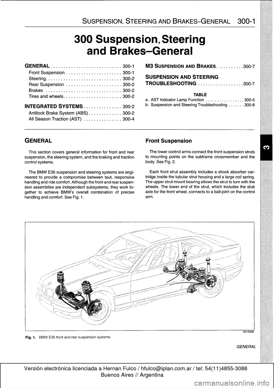
The
BMW
E36
suspension
and
steering
systems
are
engi-
neered
to
provide
a
compromise
between
taut,
responsive
handling
and
ride
comfort
.
Although
the
front
and
rear
suspen-
sion
assemblies
are
independent
subsystems,
they
work
to-
gether
to
achieve
BMW's
overall
combination
of
precise
handling
and
comfort
.
See
Fig
.
1
.
Fig
.
1
.
BMW
E36
front
and
rear
suspension
systems
.
Each
front
strut
assembly
includes
a
shock
absorber
car-
tridgeinside
the
tubular
strut
housing
and
a
large
coil
spring
.
The
upper
strut
mount
bearing
allows
the
strutto
turnwith
the
wheels
.
The
lower
end
of
the
strut,
which
includes
the
stub
axle
for
the
front
wheel,
connects
to
a
ball-joint
on
the
control
arm
.
0013098
GENERAL
Page 253 of 759
NOTE-
The
traction
control
system
referred
to
as
AST
(all
sea-
son
traction)
may
also
be
referred
to
as
ASC
(Automat-
ic
Stability
Control)
and
ASC+T
(Automatic
Stability
Control+Traction)
.
The
AST
system
improves
traction
by
electronically
apply-
ing
the
rear
brakes
when
therear
drive
wheels
are
spinning
at
a
faster
rate
than
the
front
wheels
.
The
combined
ABS/AST
control
module,
operating
through
the
ABS
hydraulic
control
unit,
modulates
braking
force
at
therear
wheels
.
In
addition,
AST
uses
retarded
ignition
timing
and
an
auxil-iary
engine
throttle
plate
to
reduceengine
torque
and
maintain
vehicle
stability
.
The
auxiliary
throttle
plate
is
held
open
by
spring
pressure
.
The
AST
system
actívates
the
auxiliary
throttie
position
motor
(ADS)
to
cose
the
AST
throttle
as
needed
.
This
reduces
the
volume
of
engine
intake
air
.
Due
to
the
throttle
closing
very
rapidly
during
AST
operationthe
driver
cannot
increase
theengine
power
output
regardless
of
how
far
theaccelerator
pedal
is
pushed
to
the
floor
.
The
auxiliary
throttle
plate
is
placed
ahead
of
the
conven-
tional
throttle
plate
in
the
throttle
body
.
Traction
control
also
comes
into
operationduringdecelera-
tion
.
Decelerating
on
snowy
or
icy
road
surfaces
can
lead
to
rear
wheel
slip
.
If
a
rear
wheel
startsto
drag
or
lock
up
when
the
throttle
is
closed
rapidly
orduringdownshifting,the
AST
system
can
limit
the
problem
by
advancing
the
ignition
timing
.
A
switch
on
the
center
console
is
used
to
togglethe
AST
on
or
off
.
The
AST
system
is
designed
to
be
maintenance
free
.
There
are
no
adjustments
that
can
be
made
.
Repair
and
trouble-
shooting
of
the
AST
system
requires
special
test
equipment
andknowledgeand
should
be
performed
only
by
an
autho-
rized
BMW
dealer
.
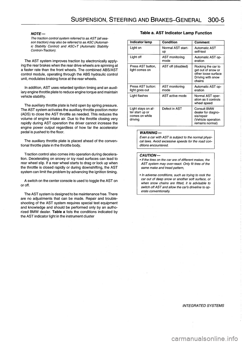
Table
a
lists
theconditions
indicated
by
the
AST
indicator
light
in
the
instrument
cluster
SUSPENSION,
STEERING
AND
BRAKES-GENERAL
300-5
Tablea
.
AST
Indicator
Lamp
Function
Indicator
lamp
1
Condition
1
Comment
Light
on
Normal
AST
start-
Automatic
AST
up
self-test
Light
off
AST
monitoring
Automatic
AST
op-
mode
eration
Press
AST
button,
AST
off
(disabled)
Rocking
the
car
tolight
comes
on
getout
of
snow
or
other
loose
surface
Driving
with
snow
chains
Press
AST
button
:
AST
monitoring
Automatic
AST
op-
light
goes
out
I
mode
eration
Light
flashes
AST
active
mode
I
Normal
AST
oper-
ation
as
it
controls
wheel
speed
Light
stays
on
af-
Defect
in
AST
Consult
BMW
ter
start
up
or
dealer
for
diagno-
comes
on
while
sis/repair
driving
(Vehicle
operation
remains
normal)
WARNING
-
Even
a
car
with
AST
is
subject
to
the
normal
physi-
cal
laws
.
Avoid
excessive
speeds
for
the
road
con-
ditions
encountered
.
CAUTION-
"
If
the
tires
on
the
carare
of
different
makes,
the
AST
system
may
over-react
.
Only
fit
tires
of
the
same
make
and
tread
pattem,
"In
adverse
conditions,
such
as
trying
to
rock
the
car
outof
deep
snow
or
another
soft
surface,
or
when
snow
chainsare
fitted,
it
is
advisable
to
switch
off
AST
and
allow
the
cars
driveline
to
op-
erate
conventionally
.
INTEGRATED
SYSTEMS
Page 271 of 759
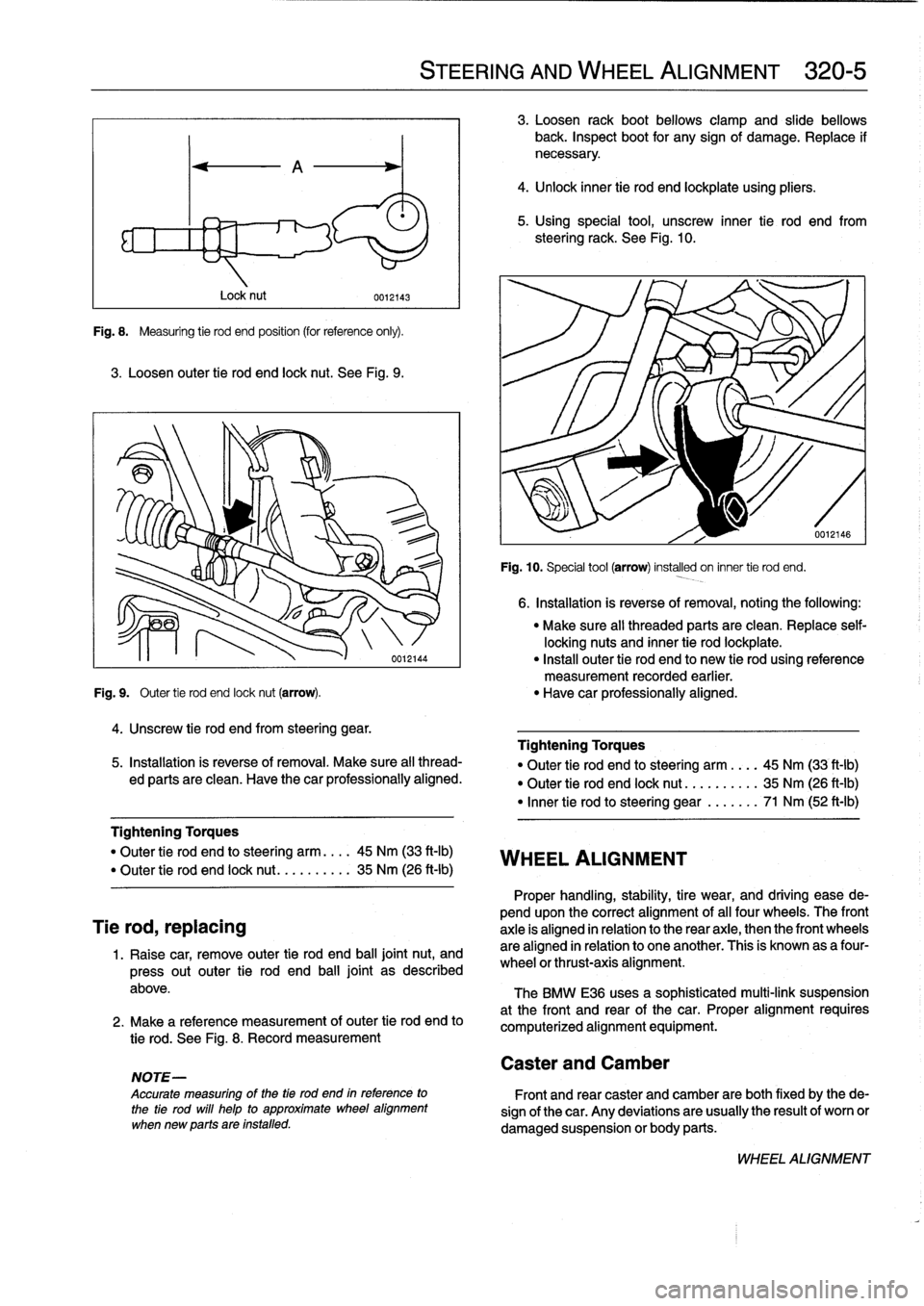
Fig
.
8
.
Measuring
tie
rod
end
position
(for
reference
only)
.
3
.
Loosen
outer
tie
rod
end
lock
nut
.
See
Fig
.
9
.
Lock
nut
4
.
Unscrew
tie
rod
end
from
steering
gear
.
0012143
"
Make
sure
all
threaded
parts
are
clean
.
Replace
self-
locking
nuts
and
inner
tie
rod
lockplate
.
"
Install
outer
tie
rod
end
to
new
tie
rod
using
reference
measurement
recorded
earlier
.
Fig
.
9
.
Outer
tie
rod
end
lock
nut
(arrow)
.
"
Have
car
professionally
aligned
.
5
.
Installation
is
reverse
of
removal
.
Make
sure
all
thread-
ed
parts
are
clean
.
Have
thecar
professionally
aligned
.
Tightening
Torques
"
Outer
tie
rod
end
losteering
arm
....
45
Nm
(33
ft-Ib)
"
Outer
tie
rod
end
lock
nut
..
.......
.
35
Nm
(26
ft-Ib)
Tie
rod,
replacing
1
.
Raise
car,
remove
outer
tie
rod
end
ball
jointnut,
and
press
out
outer
tie
rod
end
ball
joint
as
described
above
.
2
.
Make
a
reference
measurement
of
outer
tie
rod
end
to
tie
rod
.
See
Fig
.
8
.
Record
measurement
NOTE-
Accurate
measuring
of
the
tía
rod
end
in
reference
to
the
tie
rod
will
help
to
approximate
wheel
alignment
when
new
parts
are
installed
.
STEERING
AND
WHEEL
ALIGNMENT
320-
5
3
.
Loosen
rack
boot
bellows
clamp
and
slide
bellows
back
.
Inspect
boot
for
any
signof
damage
.
Replace
if
necessary
.
4
.
Unlock
inner
tie
rod
end
lockplate
using
pliers
.
5
.
Using
special
tool,
unscrew
inner
tie
rod
end
from
steeringrack
.
See
Fig
.
10
.
WHEEL
ALIGNMENT
Caster
and
Camber
Fig
.
10
.
Special
tool
(arrow)
installed
on
inner
tie
rod
end
.
6
.
Installation
is
reverse
of
removal,
noting
the
following
:
Tightening
Torques
"
Outer
tie
rod
end
to
steering
arm
..
.
.
45
Nm
(33
ft-Ib)
"
Outer
tie
rod
end
lock
nut
..........
35
Nm
(26
ft-Ib)
"
Inner
tie
rod
to
steering
gear
.......
71
Nm
(52
ft-Ib)
Proper
handling,
stability,
tire
wear,
and
driving
ease
de-
pendupon
the
correct
alignment
of
al¡
four
wheels
.
The
front
axle
is
aligned
in
relation
to
the
rear
axie,
then
the
front
wheels
are
aligned
in
relation
to
one
another
.
This
is
known
as
a
four-
wheel
or
thrust-axis
alignment
.
The
BMW
E36
uses
a
sophisticated
multi-link
suspension
at
the
front
and
rear
of
the
car
.
Proper
alignment
requires
computerized
alignment
equipment
.
Front
and
rear
caster
and
Camber
are
both
fixed
by
the
de-
sign
of
the
car
.
Any
deviations
are
usually
the
result
of
worn
or
damaged
suspension
or
body
parts
.
WHEEL
ALIGNMENT
Page 280 of 759
330-
8
REAR
SUSPENSION
CV
boot,
replacing
NOTE-
"
The
outer
CV
joint
cannot
be
removed
from
the
axle
shaft
.
In
order
to
replace
the
outer
CV
boot,
it
is
nec-
essary
to
remove
the
inner
joint
and
boot
first
.
"
If
the
CV
joints
are
worn
or
defective,
acomplete
re-
built
axle
shaft
is
available
from
an
authorized
BMW
dealerparts
department
.
1
.
Remove
drive
axle
from
car
as
described
above
.
2
.
Remove
inner
and
outer
CV
boot
clamping
bands
and
cut
old
boots
off
joints
and
shaft
.
Clean
grease
from
joints
.
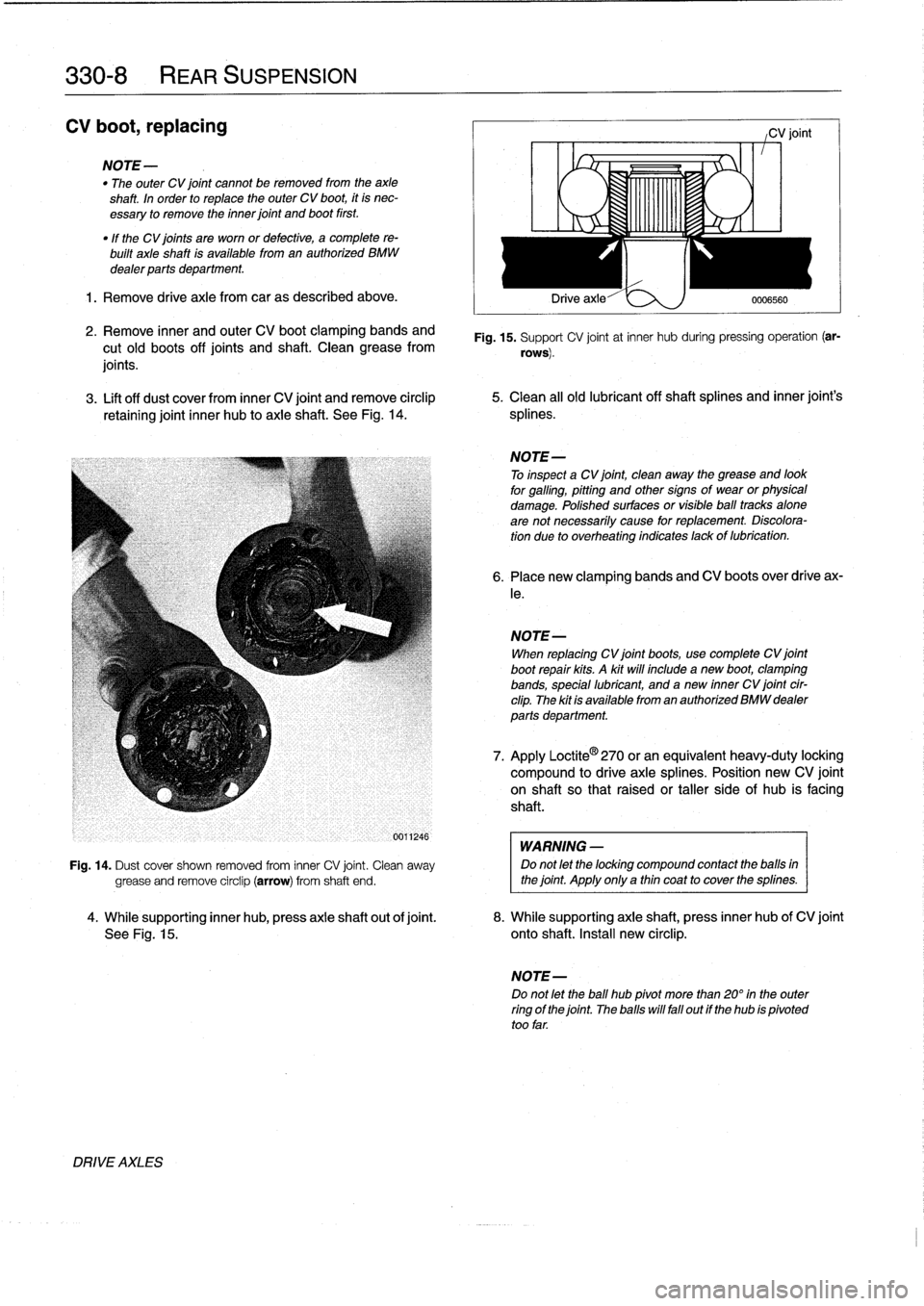
3
.
Lift
off
dust
cover
from
inner
CV
joint
and
remove
circlip
5
.
Clean
all
old
lubricantoff
shaftsplines
and
inner
joint's
retaining
joint
inner
hub
to
axle
shaft
.
See
Fig
.
14
.
splines
.
DRIVE
AXLES
-0
1
,
1
1,1
1
L
"I
C
OYA
Drive
axle-"
e
:>,
)
0006560
CV
joint
Fig
.
15
.
Support
CV
joint
at
inner
hub
duringpressing
operation
(ar-
rows)
.
NOTE-
To
inspect
a
CV
joint,
clean
away
the
grease
and
look
for
galling,pittihg
and
othersigns
of
wear
or
physical
damage
.
Polished
surfaces
or
visible
ball
tracks
alone
are
not
necessarily
cause
for
replacement
.
Discolora-
tion
due
to
overheating
indicates
lackof
lubrication
.
6
.
Place
new
clamping
bands
and
CV
boots
over
drive
ax-
le
.
NOTE-
When
replacing
CV
joint
boots,
usecomplete
CV
joint
boot
repair
kits
.
A
kit
will
include
a
new
boot,
clamping
bands,
special
lubricant,
and
anew
inner
CV
joint
cir-
clip
.
The
kit
is
available
from
an
authorized
BMW
dealer
parts
department
.
7
.
Apply
Loctite
®
270
or
an
equívalent
heavy-duty
lockíng
compound
to
drive
axlesplines
.
Position
new
CV
joint
on
shaft
so
that
raisedor
taller
side
of
hub
is
facing
shaft
.
WARNING
-
Fig
.
14
.
Dust
cover
shown
removed
from
inner
CV
joint
.
Clean
away
Do
not
let
the
locking
compound
contact
the
balls
in
grease
and
remove
circlip
(arrow)
from
shaft
end
.
the
joint
.
Apply
only
a
thin
coat
to
cover
the
splines
.
4
.
While
supporting
inner
hub,
press
axle
shaft
out
of
joint
.
8
.
While
supporting
axle
shaft,
press
inner
hub
of
CV
joint
See
Fig
.
15
.
onto
shaft
.
Install
new
circlip
.
NOTE-
Do
not
let
the
ball
hub
pivot
more
than
20°
in
the
outer
ring
of
the
joint
.
The
halls
will
fall
out
if
the
hub
ís
pivoted
too
far
.
Page 281 of 759
9
.
Packeach
CV
joint
and
rubber
boot
with
specified
REAR
SUSPENSION
ARMS
amount
of
lubricant
supplied
.
Apply
adhesive
to
large
end
of
boot
and
mount
it
on
joint
.
Secure
boot
with
clamps
.
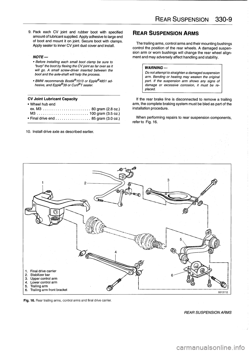
The
trailing
arms,
control
arms
and
their
mountingbushings
Apply
sealer
to
inner
CV
joint
dust
cover
and
instan
.
control
the
position
of
the
rear
wheels
.
A
damaged
suspen-
sion
arm
or
worn
bushings
will
change
the
rear
wheel
align
NOTE-
ment
and
may
adversely
affect
handling
and
stability
.
"
Before
installing
each
small
boot
clamp
be
sure
to
"burp"
the
boot
by
flexing
the
CV
joint
as
far
overas
it
WARNING
will
go
.
A
small
screw-driver
inserted
between
the
Do
notattempt
to
straighten
a
damaged
suspension
boot
and
the
axle-shaft
will
help
the
process
.
arm
.
Bending
or
heating
may
weaken
the
original
"
BMW
recommends
Bostil101513
or
EppleC4851
ad-
part
.
If
the
suspension
arm
shows
any
signs
of
hesive,
and
Epple®39
or
Curil©T
sealer
damage
or
excessive
corrosion,
it
must
be
re-
placed
.
CV
Joint
Lubricant
Capacity
"
Wheel
hub
end
ex
.
M3
..
..
.
....
.
.............
80
gram
(2.8
oz
.)
M3
..
...
.
..
.................
100
gram
(3
.5
oz
.)
"
Finaldrive
end
.................
85
gram
(3
.0
oz
.)
10
.
Install
drive
axle
as
described
earlier
.
1
.
Final
drive
carrier
2
.
Stabilizer
bar
3
.
Upper
control
arm4
.
Lower
control
arm5
.
Trailing
arm6
.
Trailing
arm
front
bracket
Fig
.
16
.
Rear
trailing
arms,
control
arms
and
final
drive
carrier
.
If
the
rear
brake
cine
is
disconnected
to
remove
a
trailing
arm,
the
complete
braking
system
must
be
bled
as
partof
the
installation
procedure
.
When
performing
repairs
to
rear
suspension
components,
refer
to
Fig
.
16
.
REAR
SUSPENSION
330-
9
0013112
REAR
SUSPENSION
ARMS
Page 299 of 759
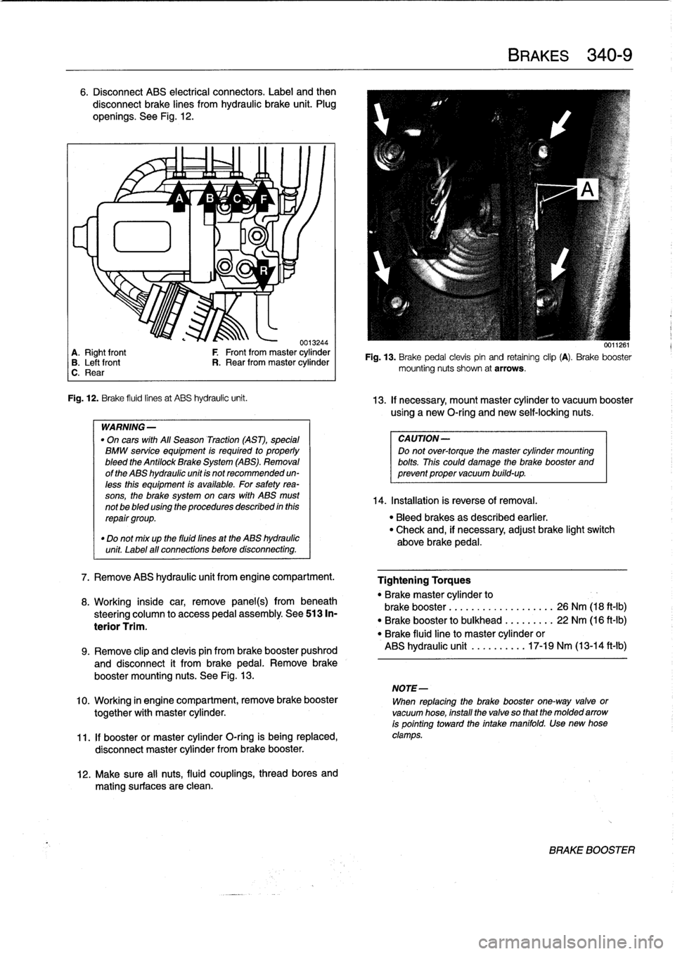
6
.
Disconnect
ABS
electrical
connectors
.
Label
and
then
disconnect
brake
lines
from
hydraulic
brake
unit
.
Plug
openíngs
.
See
Fig
.
12
.
~
~
A
1/
B
'1v
C
~
F
lu
11
-ri
J
.
0013244
A
.
Right
front
F
Front
from
master
cylinder
B
.
Leftfront
R
.
Rear
from
master
cylinder
C
.
Rear
Fig
.
12
.
Brake
fluid
linesat
ABS
hydraulic
unit
.
WARNING
-
"
On
cars
with
All
Season
Traction
(AST),
special
BMW
service
equipment
is
required
to
properly
bleed
the
Antilock
Brake
System
(ABS)
.
Removal
of
the
ABS
hydraulic
unit
is
not
recommended
un-
less
this
equipment
is
available
.
For
safetyrea-
sons,
the
brake
system
on
cars
with
ABS
must
not
be
bled
using
the
procedures
described
inthis
repair
group
.
"
Do
not
mix
up
the
fluid
fines
at
the
ABS
hydraulic
unit
Label
all
connections
before
disconnecting
.
7
.
Remove
ABS
hydraulic
unit
from
engine
compartment
.
8
.
Working
inside
car,
remove
panel(s)
frombeneath
steering
column
to
access
pedal
assembly
.
See513
In-
terior
Trim
.
12
.
Make
sure
al¡
nuts,
fluid
couplings,
thread
bores
and
mating
surfaces
are
clean
.
BRAKES
340-
9
0011261
Fig
.
13
.
Brake
pedal
clevispin
and
retaining
clip
(A)
.
Brake
booster
mounting
nuts
shown
at
arrows
.
13
.
If
necessary,
mount
master
cylinder
to
vacuum
booster
using
a
new
O-ríng
and
newself-locking
nuts
.
CAUTION-
Do
not
over-torque
the
master
cylinder
mounting
bolts
.
This
could
damage
the
brake
booster
and
prevent
proper
vacuum
build-up
.
14
.
Installation
is
reverse
of
Rmoval
.
"
Bleed
brakes
as
described
earlier
.
"
Check
and,
if
necessary,
adjust
brake
light
switch
above
brake
pedal
.
Tightening
Torques
"
Brakemaster
cylinder
to
brake
booster
...........
.
..
..
...
26
Nm
(18
ft-Ib)
"
Brake
booster
to
bulkhead
.
.
..
..
...
22
Nm
(16
ft-Ib)
"
Brake
fluidline
to
master
cylinder
or
ABS
hydraulic
unit
.......
.
..
17-19
Nm
(13-14
ft-lb)
9
.
Remove
clip
and
clevis
pin
from
brake
booster
pushrod
and
disconnect
it
from
brakepedal
.
Remove
brake
booster
mounting
nuts
.
See
Fig
.
13
.
NOTE-
10
.
Working
in
engine
compartment,
remove
brake
booster
When
replacing
the
brake
booster
one-way
valve
or
together
with
master
cylinder
.
vacuum
hose,
install
the
valve
so
that
the
molded
arrow
is
pointing
toward
the
intake
manifold
.
Use
new
hose
11
.
If
booster
or
master
cylinder
O-ring
is
being
replaced,
clamps
.
disconnect
master
cylinder
from
brake
booster
.
BRAKE
BOOSTER
Page 336 of 759
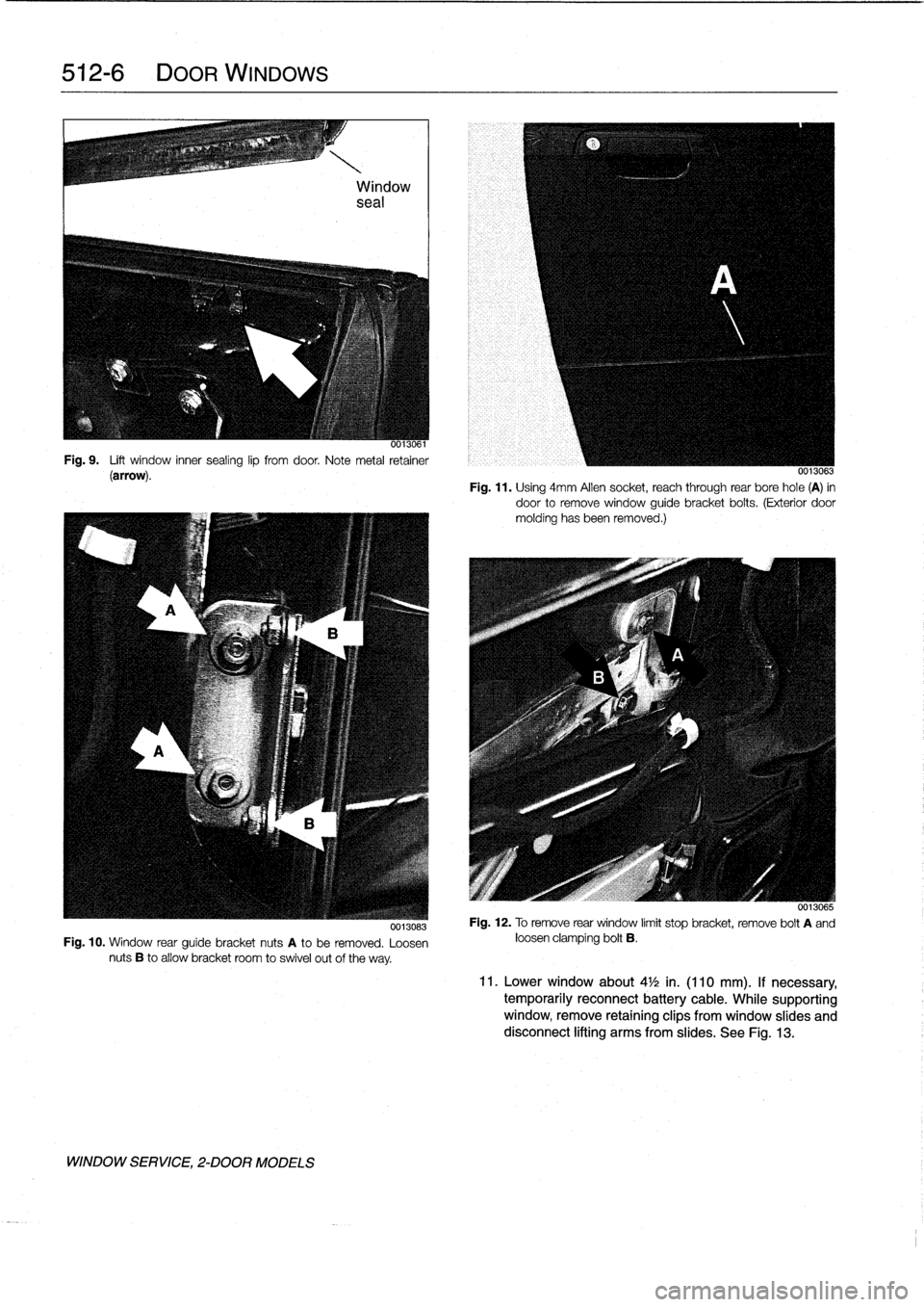
512-
6
DOORWINDOWS
0013061
Fig
.
9
.
Lift
window
inner
sealing
lip
fromdoor
.
Note
metal
retainer
(arrow)
.
0013083
Fig
.
10
.
Window
rear
guíde
bracket
nuts
A
to
be
removed
.
Loosen
nuts
B
to
allow
bracket
room
to
swivel
out
of
the
way
.
WINDOW
SERVICE,
2-DOOR
MODELS
0013063
Fig
.
11
.
Using
4mm
Allen
socket,
reach
through
rear
bore
hole
(A)
in
door
to
remove
window
guide
bracket
boits
.
(Exterior
door
molding
hasbeen
removed
.)
0013065
Fig
.
12
.
Toremove
rear
window
limit
stop
bracket,
remove
bolt
A
and
loosen
clamping
bolt
B
.
11
.
Lower
window
about
4
1
/2
in
.
(110
mm)
.
If
necessary,
temporarily
reconnect
battery
cable
.
While
supporting
window,
remove
retaining
clips
from
window
slides
and
disconnect
lifting
arms
from
slides
.
See
Fig
.
13
.
Page 438 of 759
620-2
INSTRUMENTS
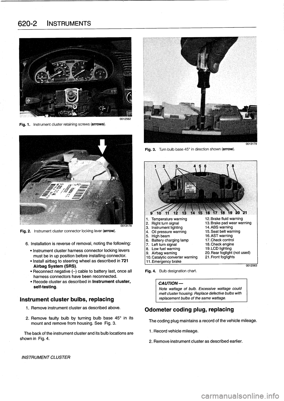
Fig
.1.
Instrument
cluster
retaining
screws
(arrows)
.
INSTRUMENT
CLUSTER
0012562
Fig
.
3
.
Turnbulb
base
45°
in
direction
shown
(arrow)
.
l
v
w
r
v
9
10
11
12
13
14
15
16
)7
18
19
20
y
21
1
.
Temperature
warning
12
.
Brake
fluid
warning
oo13n6
2
.
Right
turn
signal
13
.
Brake
pad
wear
warning
3
.
Instrument
lighting
14
.ABS
warning
Fig
.
2
.
Instrument
cluster
connector
locking
lever
(arrow)
.
4
.
Oil
pressure
warning
15
.
Seat
belt
warning5
.
Highbeam
16
.ASTwarning
6
.
Battery
charging
lamp
17
.Check
control
6
.
Installation
is
reverse
of
removal,
noting
the
following
:
7
.
Left
turn
signal
18
.Check
engine
"
Instrument
cluster
harness
connector
locking
levers
8
.
Low
fuel
warning
19
.
LCD
lighting
must
be
in
up
position
before
installing
connector
.
9
.
Airbag
warning
20
.
Rear
foglight
(not
used)
10
.
Catalytic
converter
warning
21
.
Front
foglights
"
Install
airbag
to
steering
wheel
as
described
in
721
11
.
Emergency
brake
Airbag
System
(SRS)
.
0012563
"
Reconnect
negative
(-)
cable
to
battery
last,
once
al¡
Fig
.
4
.
Bulb
designation
chart
.
harness
connectors
have
been
reconnected
.
"
Recode
cluster
as
described
in
Instrument
cluster,
CAUTION-
seif-testing
.
Note
wattage
of
bulb
.
Excessive
wattage
could
melt
cluster
housing
.
Replace
defective
bulbs
with
Instrument
cluster
bulbs,
replacing
reptacementbulbs
of
the
same
wattage
.
1
.
Remove
instrument
cluster
as
described
above
.
Odometer
coding
plug,
replacing
2
.
Remove
faulty
bulb
by
turning
bulb
base
45°
inits
mount
and
remove
from
housing
.
See
Fig
.
3
.
The
coding
plug
maintains
a
record
of
thevehicle
mileage
.
The
back
of
the
instrument
cluster
and
its
bulb
locations
are
1
.
Record
vehicle
mileage
.
shown
in
Fig
.
4
.
2
.
Remove
instrument
cluster
as
described
earlier
.