ecm relay BMW 323i 1998 E36 Workshop Manual
[x] Cancel search | Manufacturer: BMW, Model Year: 1998, Model line: 323i, Model: BMW 323i 1998 E36Pages: 759
Page 46 of 759
100-4
ENGINE-GENERAL
'
TEMP
PRECAT
POST
CAT
OXYGENSENSOR
HEATING
#
.
THROTTLE
POSITION
FUEL
INJECTOR
CONTROL
(SEQUENTIAL)
OPERATING
POWER
00
CAMSHAFT
POSITION
SENSOR
ECM
I
MAIN
GROUND
RELAY
J_
-
AC
COMPRESSOR
RELAY
CONTROL
TERMINAL
15
MEMORY
POWER
FUEL
PUMP
RELAY
CONTROL
AUX
GROUND
P
CRANKSHAFT
POSITION
dESENSOR
INTAKE
AIR
ENGINE
COOLANT
TEMP
FUEL
TANK
PRESSURE
SENSOR
S-EML
S-MSR
ASC
S-ASC
VEHICLE
SPEED
LOW
FUEL
LEVEL
A/C
SWITCH
ON
(AC)
E36
IHKA
COMPRESSOR"ON"
SIGNAL
(KO)
INDIVIDUAL
SERIAL
NUMBER
MS41
.1
SECONDARY
AIR
1NJECTION
AIR
PUMP®
RELAY
CONTROL
IDLE
CONTROL
VALVE
'M
FUEL
INJECTION
(TI)
ENGINE
SPEED
(TD)
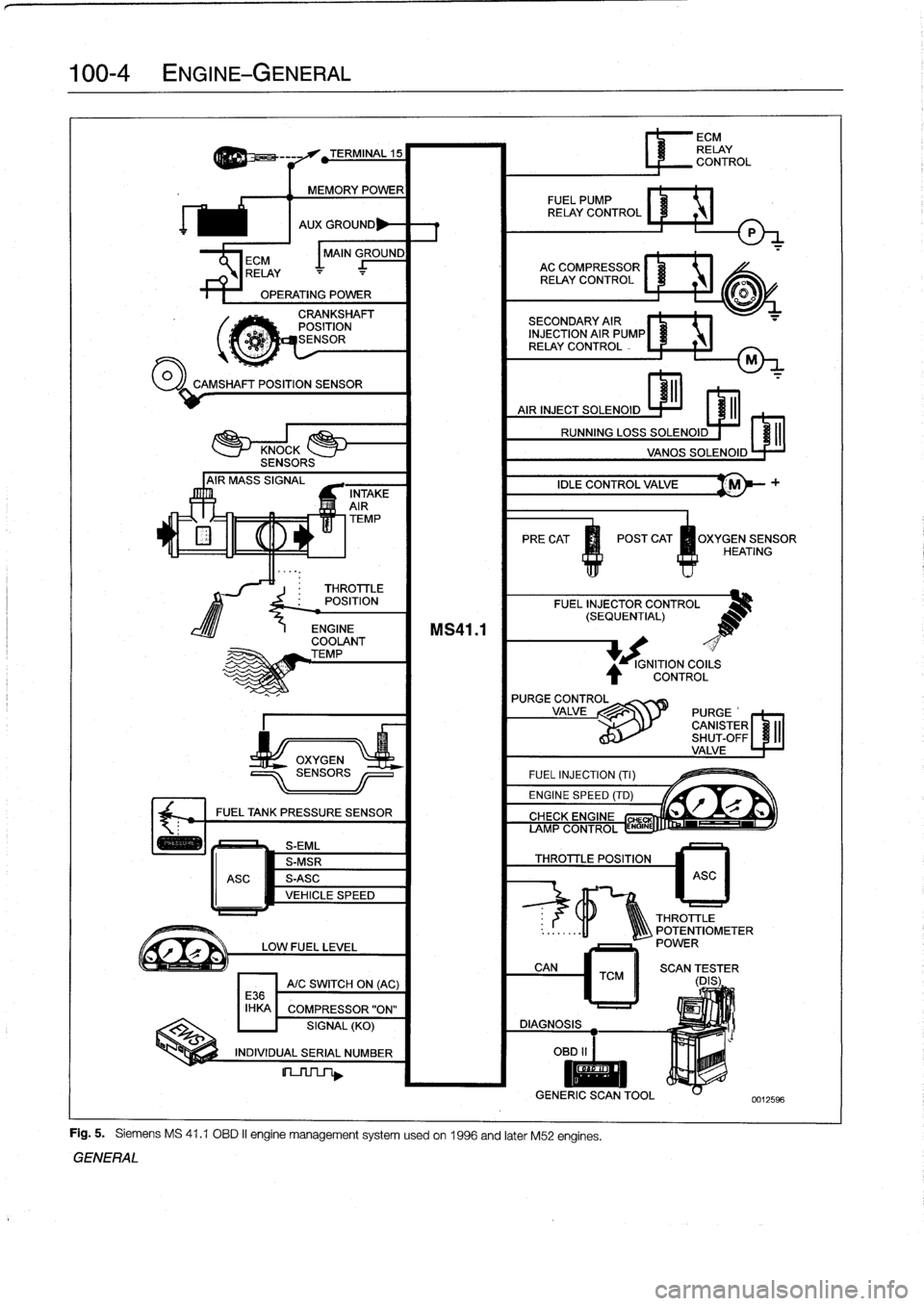
Fig
.
5
.
Siemens
MS
41
.1
OBD
II
engine
management
systemusedon
1996
and
later
M52
engines
.
GENERAL
IGNITION
COILS
CONTROL
L
r"Q
if~
CIYVFIYC
CHE
AMP
CONTROL
ENGINE
THROTTLE
POSITION
6
ECM
RELAY
CONTROL
ASC
THROTTLE
..
:
.
.
..
-11
1Q\\\
POTENTIOMETER
POWER
CAN
TCM
II
SCAN
(DES
;
ER
DIAGNOSIS
OBD
II
I
II
GENERIC
SCANTOOL
0012596
Page 48 of 759

100-6
ENGINE-GENERAL
Cylinder
compression,
checking
A
compression
tester
is
needed
to
make
a
compression
test
.
To
obtain
accurate
test
results,
the
battery
and
starter
must
be
capable
of
cranking
the
engine
at
250-300
rpm,
and
theen-
gine
should
be
at
normal
operating
temperature
.
Use
com-
pressed
air
to
clean
aroundthe
spark
plugs
before
removal
.
1
.
Disable
the
ignítion
system
by
removing
the
engine
management
system
main
relay
and
the
fuel
pump
re-
¡ay
.
See
Fig
.
6
.
WARNING
-
The
ignítion
system
produces
high
voltages
that
canbe
fatal
.
Avoid
contact
with
exposed
termínals
and
useextreme
caution
when
working
on
acar
wíth
the
ignítion
switched
on
or
the
engine
running
.
Fuel
DM
E
pump
main
re
ay
rel
ay
o
oa
ooa
.,
o00
oao
Fig
.
6
.
Engine
management
relays
in
power
distribution
box
inleft
rear
of
engine
compartment
.
CAUTION-
"
On
OBD
11
cars,
making
a
compression
test
may
causea
faultto
set
in
the
ECM
and
may
also
il-
luminate
the
Check
Engine
light
.
The
light
can
only
be
tumed
out
using
special
scan
tool
equip-
ment,using
eíther
the
BMW
specialservíce
tool
or
using
a
"generic"
OBD
11
scan
tool
.
Discon-
necting
the
battery
will
not
erase
the
fault
mem-
orynor
turn
outthe
light
.
0013034,
0012630
Fig
.
7
.
Remove
spark
plug
wires
from
spark
plugs
on
4-cylinder
en-
gine
using
special
tool
.
Tool
is
stored
under
cover
at
rear
of
cylinder
head
(arrow)
.
Fig
.
8
.
Remove
engine
cover
on
6-cylinder
engine
byprying
off
nut
covers
and
removing
nuts
(A)
.
Be
careful
not
to
let
rubber
in-
sulators
fall
off
as
cover
is
removed
(arrows)
.
4
.
On
6-cylinder
engines,
disconnect
the
harness
connec-
tors
from
the
ignítion
coils
by
lifting
the
retaining
clip
.
Remove
the
coil
mounting
nuts
andremove
the
six
coils
.
See
Fig
.
9
.
Remove
the
sparkplugs
.
"
Failure
to
remove
the
main
relay
or
attempting
to
disable
the
ignítion
system
by
other
methods
may
resultin
damage
to
the
engine
control
module
.
NOTE-
Used
sparkplugs
should
be
reinstalled
in
the
same
cyl-
2
.
On
4-cylinder
engine
:
Remove
plastic
engine
cover
from
inder
fromwhich
they
were
removed
.
top
of
cylinder
head
.
Disconnect
spark
plug
wires
and
re-
move
spark
plugs
.
See
Fig
.
7
.
5
.
Insta¡¡
the
compression
gauge
in
the
first
cylinder's
3
.
On
6-cylinder
engine
:
Remove
top
engine
coverby
pry-
spark
plug
hole,
tight
enough
to
form
a
good
seal
.
ing
off
nut
covers
and
removing
mounting
nuts
.
See
Fig
.
8
.
MECHANICAL
TROUBLESHOOTING
Page 57 of 759
al
Icld
Table
e
.
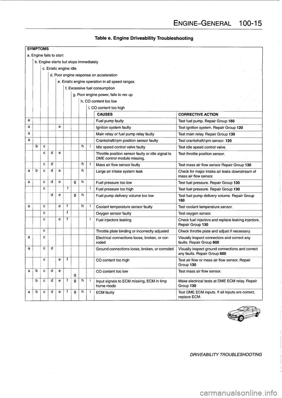
Engine
Driveability
Troubleshooting
c
l
1
I
f
I
I
Oxygen
sensor
faulty
Test
oxygen
sensor
.
ENGINE-GENERAL
100-
1
5
SYMPTOMS
a
.
Engine
fafs
tostart
b
.
Engine
startsbut
stops
immediately
c
.
Erratic
engine
idle
d
.
Poor
engine
responseon
acceleration
e
.
Erratic
engine
operation
in
al¡
speed
ranges
f
.
Excessive
fuel
consumption
g
.
Poor
enginepower,
fails
to
rev
up
h
.
CO
content
toolow
i.
CO
content
too
high
CAUSES
CORRECTIVE
ACTION
a
Fuel
pump
faulty
Test
fuel
pump
.
Repair
Group
160
a
e
Ignition
system
faulty
Test
ignition
system
.
Repair
Group
120
a
Main
relay
or
fuel
pump
relay
faulty
Test
main
relay
.
Repair
Group
130
a
Crankshaft/rpm
position
sensor
faulty
Test
crankshaft/rpm
sensor
.
120
b
c
h
i
ldle
speed
control
valve
faulty
Test
idle
speed
control
valve
.
c
d
e
Throttle
position
sensor
faulty
or
idle
signal
to
Test
throttle
position
sensor
.
DME
control
module
missing
.
c
d
h
i
Mass
air
flow
sensor
faulty
Test
mass
air
flow
sensor
Repair
Group
130
a
b
c
d
e
h
Large
air
intake
system
leak
Check
for
major
intake
air
leaks
downstream
of
mass
air
flow
sensor
.
a
c
d
e
g
h
Fuel
pressure
too
low
Test
fuel
pressure
.
Repair
Group
130
?
I
F
ue
l
pr
essu
r
e
t
oo
high
T
est
f
u
el
pressure
.
Repair
Group
130
d
e
g
h
Fuel
pump
delivery
volume
too
low
Test
fuel
pump
delivery
volume
.
Repair
Group
160
a
c
e
f
h
q
C
oo
l
a
nt
t
e
mp
e
r
a
t
u
r
e
se
n
so
r
f
au
lty
--]
T
est
coo
l
a
n
t
temp
erature
sensor
.
c
e
~
f
i
~
Fuel
injectors
leaking
Check
fuel
injectors
and
replace
leaking
injectors
.
~
Repair
Group
130
Throttle
plate
binding
or
incorrectly
adjusted
Check
throttle
plate
and
adjust
if
necessary
.
a
c
Electrical
connections
loose,
broken,
or
cor-
Visually
inspect
connectors
and
correct
any
roded
faults
.
Repair
Group
600
Ground
connections
loose,
broken,
or
corroded
Visually
inspect
ground
connections
and
correct
any
faults
.
Repair
Group
600
c
e
~
f
CO
content
too
high
Test
air
flowor
mass
air
flow
sensor
.
Repair
~
Group
130
a
b
c
d
e
CO
content
too
low
Test
mass
air
flow
sensor
.
gb
c
d
e
f
g
h
i
Inputsignals
to
ECM
missing,
ECM
in
limp
Make
electrical
tests
at
DMEECM
relay
.
Repair
home
mode
Group
130
a
~
b
~
c
~
d
e]
f
g
h
i
ECM
faulty
Test
DMEECM
inputs
.
If
all
inputs
are
correct,
replace
ECM
.
DRIVEABILITY
TROUBLESHOOTING
Page 147 of 759
GENERAL
.
.
.
.
.
.
.
.
.
...
.
.
.
.
.
.
.
.........
130-2
Intake
air
temperature
(IAT)
sensor,
Principles
of
Operatinn
.
.
.
.
.
.
.
.
.
.........
130-2
testing
and
replacing
...
.
...
.
.
.
.......
.
130-19
Basic
Engine
Settings
.
.
.
.
.
.
.
.
.
.
.
.
.
.
...
:
.
130-3
Throttle
position
sensor
(TPS),
DISA
(Dual
Resonance
Intake
System)
.
.
.
.
.
130-3
testing
and
replacing
...
.
...
.
.
.
.
.
...
.
.
.130-19
On-Board
Diagnostics
(OBD)
Idle
speed
control
valve,
testing
.
.
.
.
.
.
.
.
.
.
130-20
and
Fault
Diagnosis
.
.
....
.
......
.
.
.
...
130-4
Idle
speed
control
valve,
replacing
.
.
.
.
.
.
..
130-21
SecondaryAir
Injection
.
.
.....
.
.........
.
130-5
BOSCH
DME
M5
.2
COMPONENT
Warnings
and
Cautions
.
.
...
.
.
.
.........
.
130-6
REPLACEMENT
.....
.
......
.
....
.
.
.
..
130-21
ELECTRICAL
CHECKSAND
Mass
air
flow
sensor,
replacing
.
.
....
.
....
130-22
COMPONENT
TESTING
.
.
.
.
.
.
.
.
...
.
.
.
.
.
130-7
Engine
coolant
temperature
(ECT)
Main
sensor,
replacing
..
.
.
.
.
.
.
.
.
.
.
.
.
.
.
.
.
.
.
130-22
rela
y
testing
130
-7
,...
.
.
.
.
.
.
.
.
.
...
.
.
.
.
.
.
.
Intake
air
temperature
(IAT)
sensor,
Fuel
pump
relay,
testing
.
.
.
.
.
.
.
...
.
.
.
.
.
.
.
130-7
rep
lacin
.
.
.
.
.
.
.
.
.
.
.g
.
.
.
.
.
.
.
...
.
.
.
..
.130-22
Oxygen
sensor,
testing
(Boschsystems
only)
130-8
Throttle
poson
sensor
(TPS)
replacing
13022
,
..
.-
FUEL
DELIVERY
TESTS
...
.
....
.
.
.
...
.
130-9
Idle
speed
control
valve,
replacing
...
.
....
.130-23
Operating
fuel
pump
for
tests
.
.
.......
.
...
130-9
SIEMENS
MS
41
.1
COMPONENT
Relieving
fuel
pressure
and
REPLACEMENT
.
...
.
.
.
.
.
.......
.
....
.130-23
connecting
fuel
pressure
gauge
......
.
..
130-10
Residual
fuel
pressure,
testing
.
.....
.
.
.
.
.
130-10
Mass
air
flow
sensor,
replacing
.
.......
.
.
.130-25
Fuel
pressure
regulator
response
Engine
coolant
temperature
(ECT)
to
engine
load,
testing
.
.
.
.
.
.
.
.
.
.
.
.
.
.
.
.
130-11
sensor,
replacing
.....
.
.
.
.
.
.........
.130-25
Fuel
rail
and
injectors,
checking
...
.
.
.
.
.
.
.
130-11
Intake
air
temperature
(IAT)
sensor,
replacing
.
.
.
.
.
.....
.
.
.
.
.
.
.
.......
.
.
.130-25
Fuel
rail
and
injectors,
replacing
..
.
.
.
.
.
.
.
130-12
Throttleposition
sensor
(TPS),
replacing
.
.
.
130-26
Fuel
PressureRegulator
.........
.
.
.
.
.
.
.
130-13
Idle
s
eed
control
valve,
re
lacin
130-26
Fuel
pressure
regulatorreplacing
p
p
g
.'''...
.
'
,
(fuel
rail
mount)
...
.
.
.
.
.
.............
130-13
ECM
PIN
ASSIGNMENTS
.............
.
.
130-26
Fuel
pressure
regulator,
replacing
Engine
control
module
(ECM),
accessing
...
130-26
(undercar
mount)
.
.
.
.
.
.
.
.
.........
.
.
130-14
BOSCH
DME
M1
.7
COMPONENT
TESTS
AND
REPAIRS
.
.
.
.
.
...
.
.
.
.
.
.
.
.
130-14
Air
flow
sensor,
testing
and
replacing
.
.
.
.
.
.
130-14
Engine
coolant
temperature
(ECT)
sensor,
testing
and
replacing
...
.
.
.
.
.
.
.
.
130-15
Throttle
position
sensor
(TPS),
testing
and
replacing
.
..........
.
.....
130-16
Idle
speed
control
valve,
testing
and
replacing
.
.
.
.
.
............
130-16
BOSCH
DME
M3
.1
AND
M33
.1
COMPONENT
TESTS
AND
REPAIRS
.
.
.
130-17
Mass
Air
Flow
Sensor
.
.
.
.
.
.
.
.
.....
.
.
.
.
.130-17
Mass
air
flow
sensor
(hotwire),testing
and
replacing
.
.
.
.
.
.....
.
.
.
.
.
.
.
130-17
Mass
air
flow
sensor
(hot
film),
testíng
and
replacing
.
.
.
.....
.
.
.
.
.
.
.
.
.
130-18
Engine
coolant
temperature
(ECT)
sensor,
testing
and
replacing
..
.
.
.
.
.
...
.
130-18
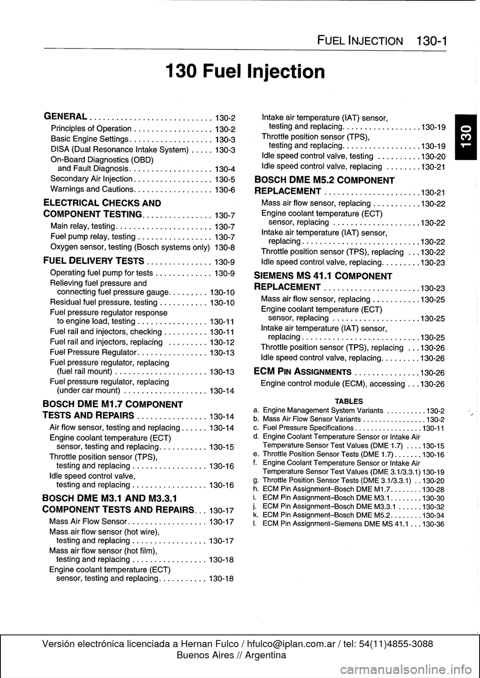
130
Fuel
i
n
jection
FUEL
INJECTION
130-1
TABLES
a
.
Engine
Management
System
Variants
.........
.130-2
b
.
Mass
Air
Flow
Sensor
Variants
..
.
..
..........
.130-2
c
.
Fuel
Pressure
Specifications
..
.
.
...
..........
130-11
d
.
Engine
Coolant
Temperature
Sensor
or
Intake
Air
Temperature
Sensor
Test
Values
(DME
1
.7)
...
.
130-15
e
.
ThrottlePosition
Sensor
Tests
(DME
1
.7)
......
.130-16
f
.
Engine
Coolant
Temperature
Sensor
or
Intake
Air
Temperature
Sensor
Test
Values
(DME
3
.1/3
.3
.1)130-19
g
.
Throttle
Position
Sensor
Tests
(DME
3
.1/3.3
.1)
.
.130-20
h
.
ECM
Pin
Assignment-Bosch
DME
M1
.7
....
.
..
.130-28
i.
ECM
Pin
Assignment-Bosch
DME
M3
.1
.......
.130-30
j
.
ECM
Pin
Assignment-Bosch
DME
M3
.3
.1
.....
.130-32
k
.
ECM
Pin
Assignment-Bosch
DME
M5
.2
.......
.
130-34
I.
ECM
Pin
Assignment-Siemens
DME
MS
41
.1
..
.
130-36
Page 150 of 759
130-
4
FUEL
INJECTION
Main
Relay
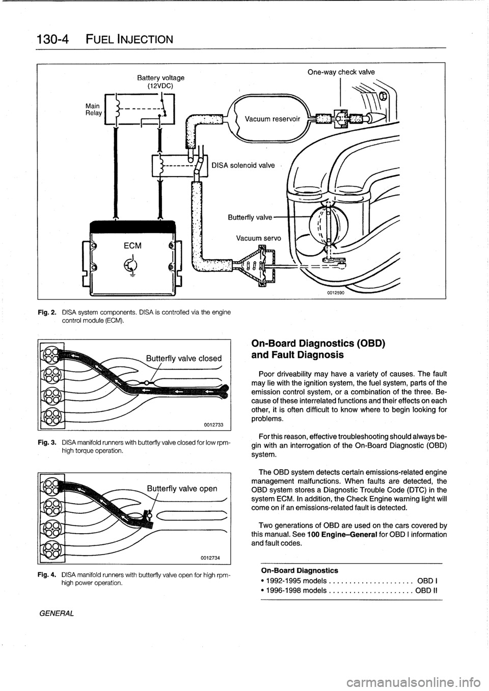
Fig
.
2
.
DISA
system
components
.
DISA
is
controlled
via
theengine
control
module
(ECM)
.
Fig
.
3
.
DISA
manifold
runners
with
butterfly
valve
closed
for
lowrpm-
high
torque
operation
.
yje
q
GENERAL
high
power
operation
.
0012734
Fig
.
4
.
DISA
manifold
runners
with
butterfly
valve
open
for
high
rpm-
On-Board
Diagnostics
(OBD)
and
Fault
Diagnosis
Poor
driveability
may
have
a
variety
of
causes
.
The
fault
may
He
withthe
ignition
system,
the
fuel
system,
parts
ofthe
emission
control
system,
ora
combination
of
thethree
.
Be-
cause
of
these
interrelated
functions
and
their
effects
on
each
other,
it
is
often
difficult
to
know
where
to
begin
looking
for
problems
.
For
this
reason,
effective
troubleshooting
should
always
be-
gin
with
an
interrogation
of
the
On-Board
Diagnostic
(01313)
system
.
The
OBD
system
detects
certain
emissions-related
engine
management
malfunctions
.
When
faults
are
detected,the
OBD
system
storesa
Diagnostic
Trouble
Code
(DTC)
in
the
system
ECM
.
In
addition,
the
Check
Engine
warning
light
will
come
on
if
an
emissions-related
fault
is
detected
.
Two
generations
of
OBD
are
used
on
thecars
covered
by
this
manual
.
See
100
Engine-General
for
OBD
I
information
and
fault
codes
.
On-Board
Diagnostics
"
1992-1995models
....
.
...
...
.
...
......
OBD
I
"
1996-1998models
....
.
..
.
.
.
..
...
......
OBD
II
Page 152 of 759
130-
6
FUEL
INJECTION
Warnings
and
Cautions
For
personal
safety,
as
well
as
the
protection
of
sensitive
electronic
components,
the
following
warnings
and
cautions
should
be
adhered
to
when
working
on
the
engine
manage-
ment
system
.
GENERAL
WARNING
-
"
The
ignition
system
produces
high
voltages
that
can
be
fatal
.
Avoid
contact
with
exposed
termi-
nals
.
Use
extreme
caution
when
working
onacar
with
the
ignition
switched
on
or
the
engine
run-
ning
.
"
Do
not
touch
or
disconnect
any
high
voltage
ca-
bles
from
the
coils
or
spark
plugs
while
the
engine
is
running
or
beingcranked
by
the
starter
.
"
Connect
and
disconnect
the
DME
system
wiring
and
test
equipment
leads
only
when
the
ignition
is
switched
off
.
"
Gasoline
is
highly
flammable
and
fts
vaporsare
explosive
.
Do
not
smoke
or
work
on
a
car
near
heaters
or
other
fire
hazards
when
diagnosing
and
repalring
fuel
system
problems
.
Have
a
tire
extinguisher
avaílable
in
case
of
an
emergency
.
"
When
working
onan
open
fuel
system,
wear
suit-
able
hand
protection,
asprolonged
contact
wfth
fuel
can
cause
illnesses
and
skin
disorders
.
"
Renew
fuel
system
hoses,
clamps
and
O-rings
any
timethey
are
removed
.
"
Before
makingany
electrical
tests
that
require
the
engine
to
be
cranked
using
the
starter,
disable
the
ignition
system
as
described
in
120
Ignition
System
.
CAUTION-
"
Prior
to
disconnecting
the
battery,
read
the
bat-
tery
disconnectinn
cautions
given
at
the
front
of
this
manual
onpage
vifi
.
"
Do
not
connect
any
test
equipment
that
delivers
a
12-volt
power
supply
to
terminal
15
(+)
of
the
ig-
nitioncoil
.
The
current
flow
may
damage
the
ECM
.
In
general,
connect
test
equipment
only
as
speclfied
by
BMW,
this
manual,
or
the
equipment
maker
.
"
Only
use
a
digital
multlmeter
for
electrical
test
.
"
Only
use
an
LED
test
light
for
quick
tests
.
"
Disconnecting
the
battery
may
erase
fault
code(s)
stored
in
memory
.
Check
for
fault
codes
prior
to
disconnecting
the
battery
cables
.
ff
the
Check
Engine
light
ís
illuminated,
see100En-
gine-General
for
DME
fault
code
information
.
ff
any
other
system
faults
have
been
detected
(indi-
catedbyan
illuminated
warning
light),
see
an
au-
thorized
BMW
dealer
.
Additional
systems
with
self-diagnostic
capabilities
include,
ABS
(Anti-
lock
brakes),
SRS
(Airbags),
EML
and
ASC+T
and
AST
(Traction
Control)
.
"
Do
not
run
the
engine
wfth
any
of
the
spark
plug
wires
dlsconnected
.
Catalytic
converter
damage
may
result
.
"
Always
waitat
least
40
seconds
afterturning
off
the
ignition
before
removing
the
engine
control
module
(ECM)
connector
.
ff
the
connector
isre-
moved
before
this
time,
residual
power
in
the
sys-
tem
relay
may
damage
the
control
module
.
"
Cleanliness
is
essential
when
working
onan
open
fuel
system
.
Thoroughly
clean
fuel
line
con-
nections
and
surroundlng
areas
before
loosen-
ing
.
Avoid
moving
the
car
.
Only
fnstall
cleanparts
.
"
Fuel
system
cleaners
and
other
chemical
addi-
tives
other
than
those
specifically
recommended
by
BMW
may
damage
the
catalytic
converter,
the
oxygensensor
or
other
fuel
supply
components
.
Page 153 of 759
ELECTRICAL
CHECKS
AND
COMPONENT
TESTING
Main
relay,
testing
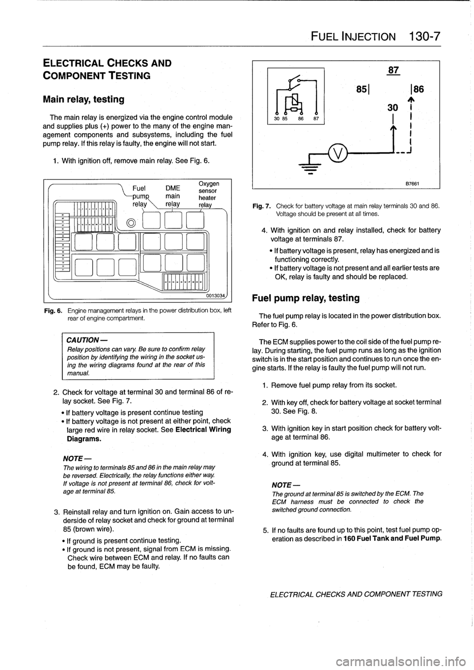
The
main
relay
is
energized
via
the
engine
control
module
and
supplies
plus
(+)
power
to
the
many
of
the
engine
man-
agement
components
and
subsystems,
including
the
fuel
pump
relay
.
If
this
relay
is
faulty,
the
engine
will
not
start
.
1
.
With
ignition
off,
remove
main
relay
.
See
Fig
.
6
.
.
iommooommmoi
~
"""
Fuel
DME
sensor
CA
UTION-
Relay
positions
can
vary
.
Be
sure
to
confirm
relay
position
by
identífyíng
the
wiring
in
the
socket
us-
ingthe
wiring
diagramsfound
at
the
rearof
this
manual
.
0013034)
Fuel
pump
relay,
testing
FUEL
INJECTION
130-
7
87
851186
30
~j
1
.
Remove
fuel
pump
relay
from
its
socket
.
87661
Fig
.
7
.
Check
for
battery
voltage
at
main
relay
terminals
30
and
86
.
Voltage
should
be
present
at
all
times
.
4
.
With
ignition
on
and
relay
installed,
check
for
battery
voltage
at
terminals
87
.
"
If
battery
voltage
is
present,relay
has
energized
and
is
functioningcorrectly
.
"
lf
battery
voltage
is
not
present
and
al¡
earlier
tests
are
OK,
relay
is
faulty
and
should
be
replaced
.
Fig
.
6
.
Engine
management
relays
in
the
power
distribution
box,
left
rear
of
engine
compartment
.
The
fuel
pump
relay
is
located
in
the
power
distribution
box
.
Refer
to
Fig
.
6
.
The
ECM
supplies
power
to
the
coil
side
of
the
fuel
pump
re-
lay
.
During
starting,
the
fuel
pump
runs
as
long
as
the
ignition
switch
isin
the
start
position
and
continues
to
run
once
theen-
gine
starts
.
If
the
relay
ís
faulty
the
fuel
pump
will
notrun
.
2
.
Check
for
voltage
at
terminal
30
and
terminal
86
of
re-
¡ay
socket
.
See
Fig
.
7
.
2
.
With
key
off,
check
for
batteryvoltage
at
socket
terminal
"
If
battery
voltage
is
present
continue
testing
30
.
See
Fig
.
8
.
"
lf
battery
voltage
is
not
present
at
either
point,
check
large
red
wire
in
relay
socket
.
See
Electrical
Wiring
3
.
With
ignition
key
in
start
position
check
for
battery
volt-
Diagrams
.
age
at
terminal
86
.
NOTE-
4
.
With
ignition
key,
use
digital
multimeter
to
check
for
The
wiring
to
terminals
85
and
86
in
the
main
relay
may
ground
at
terminal
85
.
be
reversed
.
Electrically,
the
relay
functions
either
way
.
lf
voltage
ís
not
present
at
terminal
86,
check
for
volt-
NOTE-
age
at
terminal
85
.
The
ground
atterminal
85
is
switched
by
the
ECM
.
The
ECM
hamess
must
be
connected
to
check
the
3
.
Reinstall
relay
and
turn
ignition
on
.
Gainaccess
to
un-
switched
ground
connection
.
derside
of
relay
socket
and
check
for
ground
at
terminal
85
(brown
wire)
.
5
.
If
no
faults
are
found
up
tothis
point,
testfuel
pump
op-
"
lf
ground
is
present
continue
testing
.
eration
as
described
in
160
Fuel
Tank
and
Fuel
Pump
.
"
If
ground
is
not
present,
signal
from
ECM
is
missing
.
Check
wire
between
ECM
and
relay
.
If
no
faults
can
be
found,
ECM
may
be
faulty
.
ELECTRICAL
CHECKS
AND
COMPONENT
TESTING
Page 154 of 759
130-
8
FUEL
INJECTION
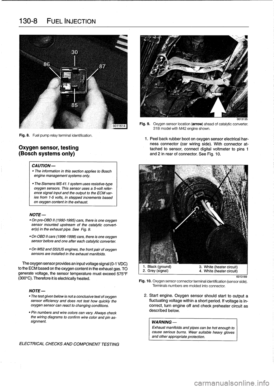
Fig
.
8
.
Fuel
pump
relayterminal
identification
.
1.
Peel
back
rubber
boot
on
oxygen
sensor
electrical
har-
ness
connector
(car
wiring
side)
.
With
connector
at-
Oxygen
sensor,
testing
tached
to
sensor,
connect
digital
voltmeter
to
pins
1
(BOSch
systems
only)
and
2
in
rear
of
connector
.
See
Fig
.
10
.
CAUTION-
"
The
information
inthis
sectionapplies
to
Bosch
engine
management
systems
only
.
"
The
Siemens
MS
41
.1
system
uses
resistive-type
oxygen
sensors
.
This
sensor
uses
a
5-volt
refer-
ence
signal
input
and
the
output
to
the
ECM
var-
ees
from
1-5
volts,
in
stepped
increments
based
on
oxygen
content
in
the
exhaust
.
NOTE-
"
On
pre-08D
11(1992-1995)
cars,
there
is
one
oxygen
sensor
mounted
upstream
of
the
catalytic
convert-
er(s)
in
the
exhaust
pipe
.
See
Fig
.
9
.
"
On
OBD
11
cars
(1996-1998)
cars,
there
is
one
oxygen
sensor
before
andone
after
each
catalytic
converter
.
"
OnM52
and
S52US
engines,
the
front
pairof
oxygen
sensors
are
installed
in
the
exhaust
manifolds
.
The
oxygen
sensor
providesan
input
voltage
signal
(0-1
VDC)
to
the
ECM
based
on
the
oxygen
content
in
the
exhaust
gas
.
TO
generate
voltage,
the
sensor
temperature
must
exceed
575°F
(300°C)
.
Therefore
it
ís
electrically
heated
.
NOTE-
"
The
test
given
below
is
not
a
conclusive
test
of
oxygen
sensor
efficiency
and
does
not
test
how
quickly
the
oxygensensor
can
react
to
changing
conditions
.
"
Pin
numbers
and
wirecolors
can
vary
.
Always
check
the
wiring
diagrams
to
conflrm
wire
color
and
pinas-
signment
.
ELECTRICAL
CHECKS
AND
COMPONENT
TESTING
0013135
Fig
.
9
.
Oxygen
sensor
location
(arrow)
ahead
of
catalytic
converter
.
3181
model
with
M42
engine
shown
.
1
.
Black
(ground)
2
.
Grey
(signal)
4
.
White
(heater
circuit)
3
.
White
(heater
circuit)
0013189
Fig
.
10
.
Oxygen
sensor
connector
terminal
identification
(sensor
sede)
.
Terminals
numbers
are
molded
into
connector
.
2
.
Start
engine
.
Oxygen
sensorshould
start
to
output
a
fluctuating
voltage
within
a
short
period
.
If
voltage
is
in-
correct,
turn
engine
off
and
check
preheater
circuit
as
described
below
.
WARNING
-
Exhaust
manifolds
and
pipes
can
be
hot
enough
to
cause
serious
burns
.
Wear
suitable
heavy
gloves
and
other
appropriate
protection
.
Page 155 of 759
Oxygen
Sensor
FUEL
DELIVERY
TESTS
FUEL
INJECTION
130-
9
"
Voltage
at
¡dle
..
.
..
..
....
0
.2
to
0
.8
VDC,
fluctuating
Checking
fuel
delivery
is
afundamental
part
of
trouble-
shooting
and
diagnosing
the
engine
management
system
.
Fuel
pressure
directly
influences
fuel
delivery
.
An
accurate
NOTE-
fuel
pressure
gauge
will
be
needed
to
make
the
tests
.
To
check
sensorresponse
to
lean
and
rich
mixtures,
createenairleak,
orpull
vacuumhoseofffue¡
pressure
There
are
three
significant
fuel
delivery
values
to
be
mea-
regulator
to
increase
fuel
pressure
.
sured
:
3
.
Separate
sensorharness
connector
from
sensor
.
Check
for
battery
voltage
between
terminals
3
and
4
(green
wire
and
brown
wire)
in
main
wiring
harness
side
of
con-
nector
with
engine
running
.
If
voltage
is
not
present,
check
oxygen
sensor
heater
relay
.
See610
Electrical
Component
Locations
.
4
.
Check
heater
element
resistance
between
terminals
3
and
4
in
sensor
side
of
connector
.
If
element
is
electri-
cally
open
(no
continuity),
replace
sensor
.
NOTE-
The
oxygen
sensor
heater
relay
is
mounted
in
the
main
power
distributfon
box
in
the
left
rear
of
the
engine
com-
partment
.
Refer
to
Fig
.
6
.
The
heater
relay
is
energized
wíth
positive
(+)
battery
voltage
from
the
main
relayanda
switched
ground
from
the
ECM
.
See
Electrical
Wir-
ing
Diagrams
.
"
Oxygen
sensor
to
exhaust
pipe
...
..
55
Nm
(41
ft-Ib)
"
System
pressure-created
by
the
fuel
pump
and
main-
tained
by
the
pressure
regulator
.
"
Fuel
delivery
volume-created
by
the
fuel
pump
and
af-
fected
by
restrictions,
suchasclogged
fuel
filter
.
"
Residual
pressure-the
pressure
maintained
in
the
closed
system
after
the
engine
and
fuel
pump
are
shut
off
.
Procedures
for
measuring
the
first
two
quantities
arede-
scribed
in
160
Fuel
Tank
and
Fuel
Pump
.
Residual
fuel
pres-
sure
is
checked
using
the
procedure
detailed
later
in
this
group
.
Operating
fuel
pump
fortests
To
operate
the
fuel
pump
for
testing
purposes
without
hav-
íng
to
runthe
engine,
the
fuel
pump
relay
can
be
bypassed
to
power
the
pump
directly
.
Fuel
pump
relay
location
is
shown
in
Fig
.
6
.
5
.
¡f
oxygen
sensor
doesn't
produce
a
fluctuating
voltage
To
runthe
fuel
pump,
remove
the
fuel
pump
relay
and
con-
and
preheater
circuit
is
OK,
replace
sensor
.
nect
the
socket
for
relayterminal
30
to
the
socket
for
relay
ter-
mina¡
87
with
a
fused
jumper
wire
.
After
completing
the
tests,
NOTE-
remove
the
jumper
wire
.
If
not
already
applied,
coat
the
oxygen
sensor
threads
with
an
anti-seize
compound
before
installation
.
Do
not
CAUTION-
getthe
compound
on
the
sensor
tip
.
"
Relay
locations
may
vary
.
Use
care
when
identi-
fying
relays
and
making
electrical
checks
at
the
fuselrelay
panel
.
See
610
Electrical
Compo
Tightening
Torque
nent
Locations
for
additional
relay
information
.
"
The
fuel
pump
relay
has
a
1
.5
mm2
red
wire
at
ter-
minal
30
in
the
relay
socket
.
Terminal
87
has
a
1
.5
mm
2
greenlviolet
wire
.
See
Electrical
Wiring
Di-
agrams
for
additional
wiring
information
.
NOTE-
Thejumper
wire
should
be
1.5
mm2
(14
ga
.)
and
in-
clude
an
in-line
tuse
holder
with
a15
amp
tuse
.
To
avoid
fuselrelay
panel
damage
from
repeated
connect-
ing
and
disconnecting,
also
include
a
toggle
switch
.
A
heavy-duty
jumper,
BMW
tool
no
.
61
3
050,
is
also
available
from
an
authorized
BMW
dealer
.
FUEL
DELIVERYTESTS
Page 157 of 759
3
.
Observe
fuel
pressure
gauge
after
20
minutes
.
The
pressure
shouldnot
drop
off
more
than
0
.5
bar
from
system
pressure
listed
in
Tablec
.
4
.
When
finished
testing,
disconnect
pressure
gauge
and
reconnect
fuel
line
.
If
the
fuel
system
does
not
maintain
pressure,
check
visual-
¡y
for
leaks
in
fuel
lines
orat
unions
.
Leaks
can
also
be
due
to
a
leaking
injector
or
a
faulty
fuel
pump
check
valve
.
Check
the
pump
check
valve
by
repeating
the
test,
butbefore
turning
the
fuel
pump
off,
pinch
off
theretum
line
at
the
fuel
rail
.
If
the
pressure
is
now
maintained,
the
fault
is
most
likely
the
fuel
pump
check
valva
.
Tabla
c
.
Fuel
Pressure
Specifications
Engine
1
Fuel
pressure
4-cytinder
1
3
.0
t
0
.2
bar
(43
.5
t
2
.9psi)
6-cytinder
M50/S50US
engine
3
.0
t
0
.2
bar
(43
.5
±2
.9psi)
M52/S52US
engine
3
.5
f
0
.2
bar
(51
t
2.9psi)
Fuel
pressure
regulator
response
to
engine
load,
testing
1
.
With
fuel
pressure
gauge
connected,
reinstallfuel
pump
relay
.
Start
engine
and
allow
it
to
idle
.
NOTE-
The
fuel
pressure
should
be
lower
by0
.4-0.7
bar
from
the
specifications
listed
in
Table
c
.
Engine
vacuum
act-
ing
on
the
fuel
pressure
regulator
diaphragm
reduces
the
fuel
pressure
.
2
.
With
engine
idling,
remove
vacuum
hose
from
regula-
tor
.
Pressure
should
increase
.
3
.
Reconnecthose
and
check
that
pressure
decreases
.
4
.
When
finished
testing,
disconnect
pressure
gauge
and
reconnect
fuelline
.
Tighten
hose
clamp
.
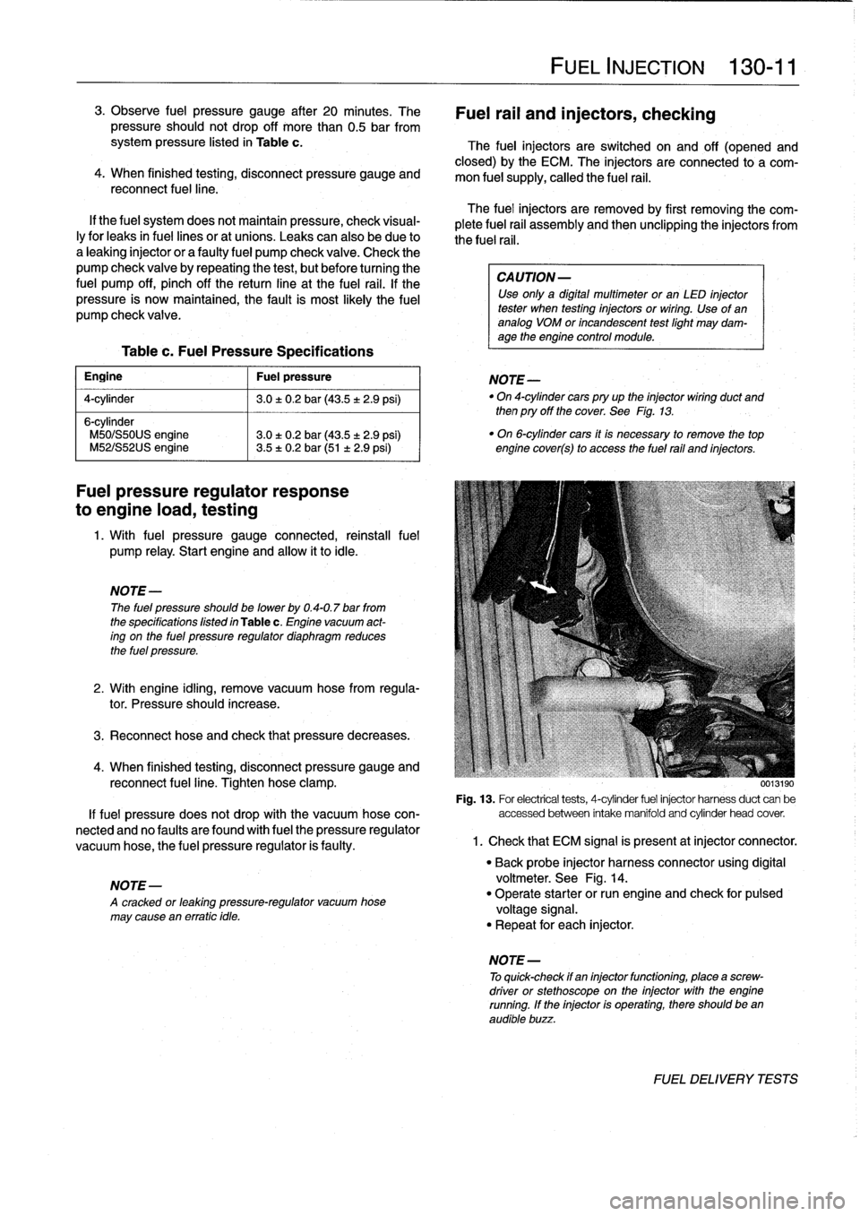
0013190
Fig
.
13
.
For
electrical
tests,
4-cytinder
fuel
injector
harnessduct
can
be
If
fuel
pressure
does
not
drop
with
the
vacuum
hose
con-
accessed
between
intake
manifold
and
cytinder
head
cover
.
nected
and
no
faulty
are
found
with
fuel
the
pressure
regulator
vacuum
hose,
the
fuel
pressure
regulator
is
faulty
.
1
.
Check
that
ECM
signal
is
present
atinjector
connector
.
NOTE-
A
cracked
or
leaktng
pressure-regulator
vacuum
hose
may
cause
en
erratic
tdle
.
FUEL
INJECTION
130-
11
Fuel
rail
and
injectors,
checking
The
fuel
injectors
are
switched
on
and
off
(opened
and
closed)
by
the
ECM
.
The
injectors
are
connected
to
a
com-
mon
fuel
supply,
callad
the
fuel
rail
.
The
fuel
injectors
are
removed
by
first
removing
the
com-
plete
fuel
rail
assembly
and
then
unclipping
the
injectors
from
the
fuel
rail
.
CA
UTION-
Use
only
a
digital
multimeter
or
an
LED
injector
tester
when
testing
injectors
or
wiring
.
Use
of
ananalog
VOM
or
incandescent
testlight
may
dam-
age
the
engine
control
module
.
NOTE-
"
On
4-cytindercars
pry
up
the
injector
wiring
duct
and
then
pry
off
the
cover
.
See
Fig
.
13
.
"
On
6-cytinder
cars
it
is
necessary
to
remove
the
top
engine
cover(s)
to
access
the
fuel
rail
and
injectors
.
"
Back
probe
injector
harness
connector
using
digital
voltmeter
.
See
Fig
.
14
.
"
Operate
starter
or
run
engine
and
check
for
pulsad
voltage
signal
.
"
Repeat
for
each
injector
.
NOTE
-
To
quick-check
if
en
injectorfunctioning,
place
a
screw-
driver
or
stethoscope
on
the
injector
with
the
engine
running
.
If
the
injector
is
operating,there
should
been
audible
buzz
.
FUEL
DELIVERYTESTS