hot wire BMW 325i 1992 E36 User Guide
[x] Cancel search | Manufacturer: BMW, Model Year: 1992, Model line: 325i, Model: BMW 325i 1992 E36Pages: 759
Page 185 of 759
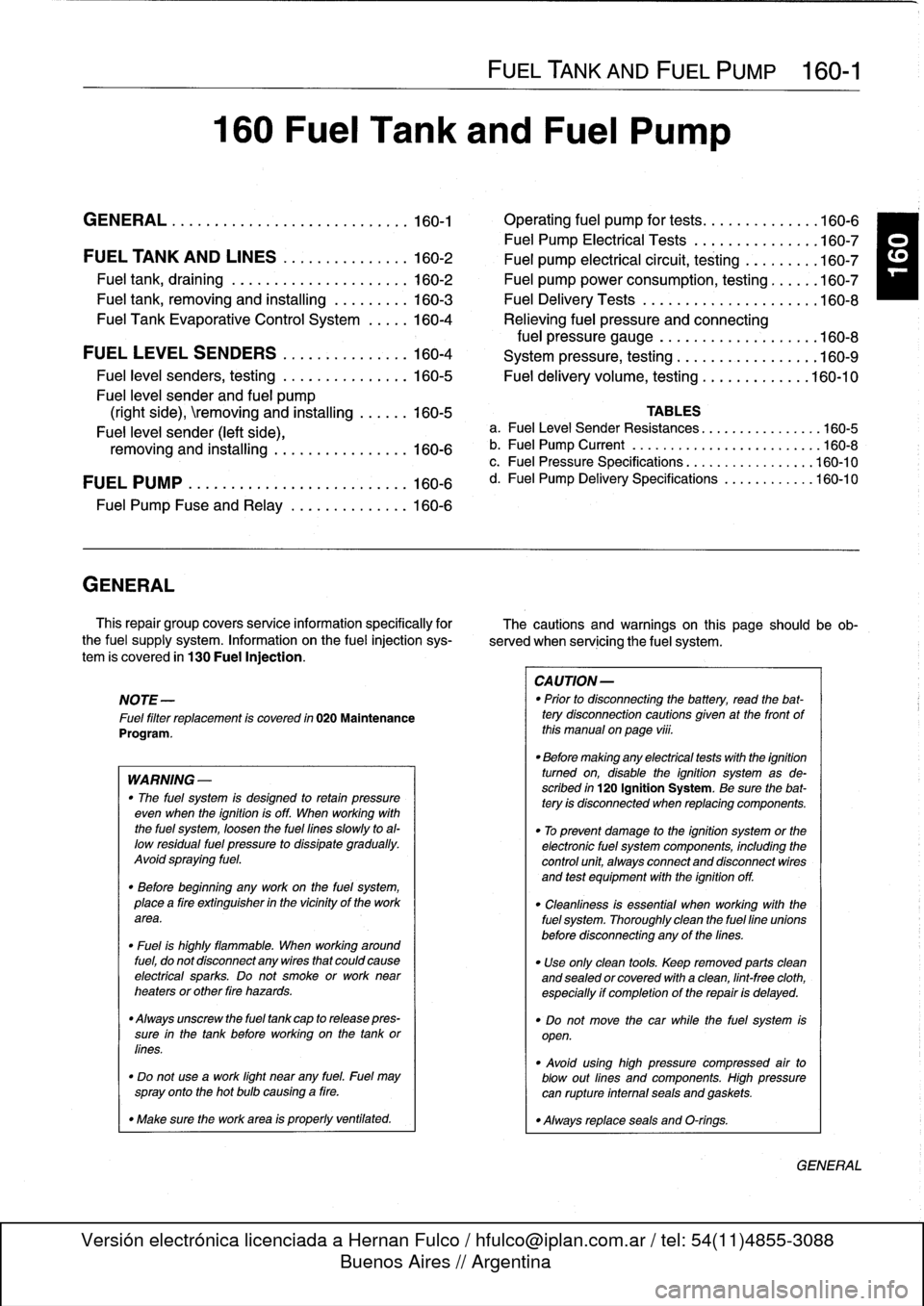
160
Fuel
Tank
and
Fuel
Pump
GENERAL
.
.
.
.
.
.
...........
.
....
.
.
.
.
.
.
160-1
Operating
fuel
pump
for
tests
.
.
.
.
.
.
.......
.160-6
Fuel
Pump
Electrical
Tests
.
.
.
.
.
.
.
...
.
.
.
.
.
160-7
FUEL
TANK
AND
LINES
..
.
.
.
..........
160-2
Fuel
pump
electrical
circuit,
testing.
...
.
.
.
.
.
160-7
Fuel
tank,
draining
..
.
.
.
.
.
.
.
.
.
..........
160-2
Fuel
pump
power
consumption,
testing
.
.
.
.
.
.
160-7
Fuel
tank,
removing
and
installing
.........
160-3
Fuel
Delivery
Tests
....
.
.
.
...
.
.....
.
.
.
..
160-8
Fuel
Tank
Evaporative
Control
System
.....
160-4
Relieving
fuel
pressure
and
connecting
fuel
pressure
gauge
..
.
...........
.
.
.
..
160-8
FUEL
LEVEL
SENDERS
.
.
.
.
.
.......
.
.
.
160-4
System
pressure,
testing
.................
160-9
Fuel
level
senders,
testing
.
.
.
.
.
.......
.
.
.
160-5
Fuel
delivery
volume,
testing
.............
160-10
Fuel
leve¡
sender
and
fuel
pump
(right
side),
emoving
and
installing
.
.
.
.
.
.
160-5
TABLES
Fuel
leve¡
sender
(left
side),
a
.
FuelLeve¡
Sender
Resistances
...........
.
.
..
.160-5
removing
and
installing
.........
.
.
.
.
.
.
.
160-6
b
.
Fuel
Pump
Current
...
.................
..
...
160-8
c
.
Fuel
Pressure
Specifications
..............
.
..
160-10
FUEL
PUMP
.
.
.
................
.
.
.
.
.
.
.
160-6
d
.
Fuel
Pump
Delivery
Specifications
.........
.
..
160-10
Fuel
Pump
Fuse
and
Relay
.
.
.
....
.
.
.
.
.
.
.
160-6
GENERAL
This
repair
group
covers
service
information
specifically
for
The
cautions
and
warnings
on
this
page
should
beob
the
fuel
supply
system
.
Information
on
the
fue¡
injection
sys-
served
when
servicing
the
fuel
system
.
tem
is
covered
in
130
Fuel
Injection
.
NOTE-
Fue¡
filter
replacement
is
covered
in
020
Maintenance
Program
.
WARNING
-
"
The
fuel
system
is
designed
to
retain
pressure
even
when
the
ignition
isoff
.
When
working
with
the
fuel
system,
loosen
the
fuel
lines
slowly
toal-
low
residual
fuel
pressure
to
dissipate
gradually
.
Avoid
spraying
fuel
.
"
Before
beginning
any
work
on
the
fuel
system,
place
a
tire
extinguisher
in
the
vicinity
of
the
work
area
.
"
Fuel
is
highly
flammable
.
When
working
around
fuel,
do
not
disconnect
any
wires
that
could
cause
electrical
sparks
.
Do
not
smoke
or
work
near
heaters
or
other
tire
hazards
.
"
Always
unscrew
the
fuel
tank
cap
to
release
pres-
sure
in
the
tank
before
working
on
the
tank
or
fines
.
"
Do
not
use
a
work
light
near
any
fuel
.
Fuel
may
spray
onto
the
hot
bulb
causing
a
tire
.
"
Make
sure
the
work
area
is
properly
ventifated
.
FUEL
TANK
AND
FUEL
PUMP
160-1
CAUTION-
"
Prior
to
disconnecting
the
battery,
read
the
bat-tery
disconnection
cautions
given
at
the
front
of
this
manual
onpage
viü
.
"
Before
making
any
electrical
tests
with
the
ignition
tumed
on,
disable
the
ignition
system
as
de-
scribed
in
120
Ignition
System
.
Be
sure
the
bat-tery
is
disconnected
when
replacing
components
.
"
To
prevent
damage
to
the
ignition
system
or
the
electronic
fuel
system
components,
including
the
control
unit,
aiways
connect
and
disconnect
wires
and
test
equipment
with
the
ignition
off
.
"
Cleanliness
is
essential
when
working
with
the
fuel
system
.
Thoroughly
clean
the
fuel
fine
unionsbefore
disconnecting
any
of
the
fines
.
"
Use
only
clean
tools
.
Keep
removed
parts
clean
and
sealed
or
covered
with
a
clean,
lint-free
cloth,
especially
if
completion
of
the
repair
is
delayed
.
"
Do
not
move
the
car
while
the
fuel
system
is
open
.
"
Avoid
using
high
pressure
compressed
air
to
blow
out
fines
and
componente
.
High
pressure
can
rupture
infernal
seals
and
gaskets
.
"
Always
replace
seals
and
O-rings
.
GENERAL
Page 192 of 759
160-
8
FUEL
TANK
AND
FUEL
PUMP
UU131
tst5
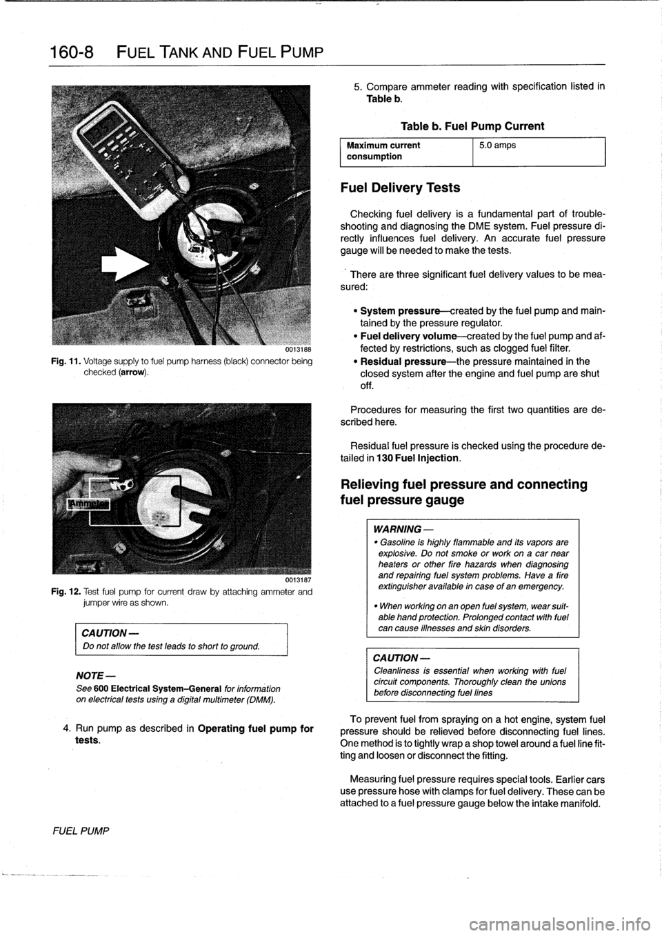
Fig
.
11
.
Voltage
supply
to
fuel
pump
harness
(black)
connector
being
checked
(arrow)
.
00131ts7
Fig
.
12
.
Test
fuel
pump
for
current
draw
by
attadhing
ammeter
andjumper
wire
as
shown
.
CAUTION-
Do
not
allow
the
test
leads
to
short
to
ground
.
NOTE-
See
600
Electrical
System-General
for
information
on
electricaltests
using
a
digital
multimeter
(DMM)
.
4
.
Run
pump
as
described
in
Operating
fuel
pump
for
tests
.
FUEL
PUMP
5
.
Compare
ammeter
reading
with
specification
listed
in
Table
b
.
Maximum
current
5
.0
amps
consumption
FuelDelivery
Tests
Table
b
.
Fuel
Pump
Current
Checking
fuel
delivery
is
a
fundamental
part
of
trouble-
shooting
and
diagnosing
the
DME
system
.
Fuelpressure
di-
rectly
influences
fuel
delivery
.
An
accurate
fuel
pressure
gauge
will
be
needed
to
make
the
tests
.
There
arethree
significant
fuel
delivery
values
to
bemea-
sured
:
"
System
pressure-created
by
the
fuel
pump
and
main-
tained
by
the
pressure
regulator
.
"
Fuel
delivery
volume-created
by
the
fuel
pump
and
af-
fected
by
restrictions,
suchas
clogged
fuel
filter
.
"
Residual
pressure-the
pressure
maintained
in
the
closed
system
after
the
engine
and
fuel
pump
areshut
off
.
Procedures
for
measuring
the
first
two
quantities
arede-
scribed
here
.
Residual
fuel
pressure
is
checked
using
the
procedurede-
tailed
in
130
Fuel
Injection
.
Relieving
fuel
pressure
and
connecting
fuel
pressure
gauge
WARNING
-
"
Gasoline
is
highly
flammable
and
its
vaporsare
explosive
.
Do
not
smoke
or
work
ona
car
near
heaters
or
other
fire
hazards
when
diagnosing
and
repairing
fuel
system
problems
.
Have
a
fire
extinguisher
available
in
case
of
an
emergency
.
"
When
working
onan
open
fuel
system,
wear
suit-
able
hand
protection
.
Prolonged
contact
with
fuel
can
cause
iflnesses
and
skin
disorders
.
CA
UTION-
Cleanliness
is
essential
when
working
withfuel
circuit
components
.
Thoroughly
clean
the
unionsbefore
disconnecting
fuel
fines
To
prevent
fuel
from
spraying
on
a
hotengine,
system
fuel
pressure
should
be
relieved
before
disconnecting
fuel
lines
.
One
method
is
to
tightly
wrap
a
shop
towel
around
a
fuel
line
fit-
ting
and
loosen
or
disconnect
the
fitting
.
Measuring
fuel
pressure
requires
special
tools
.
Earlier
cars
use
pressure
hose
with
clamps
for
fuel
delivery
.
These
can
be
attached
to
a
fuel
pressure
gauge
below
the
intake
manifold
.
Page 197 of 759
Cooling
System
Pressure
Test
If
the
engine
overheats
and
no
other
cooling
system
testsindicate
trouble,
the
radiator
may
have
some
pluggedpassag-
A
cooling
system
pressure
test
is
used
to
check
for
internal
es
that
are
restricting
coolant
flow
.
leaks
.
Some
of
the
common
sources
ofinternal
leaks
are
a
faulty
cylinder
head
gasket,
a
cracked
cylinder
head,
or
a
Temperature
Gauge
Quick
Check
cracked
cylinder
block
.
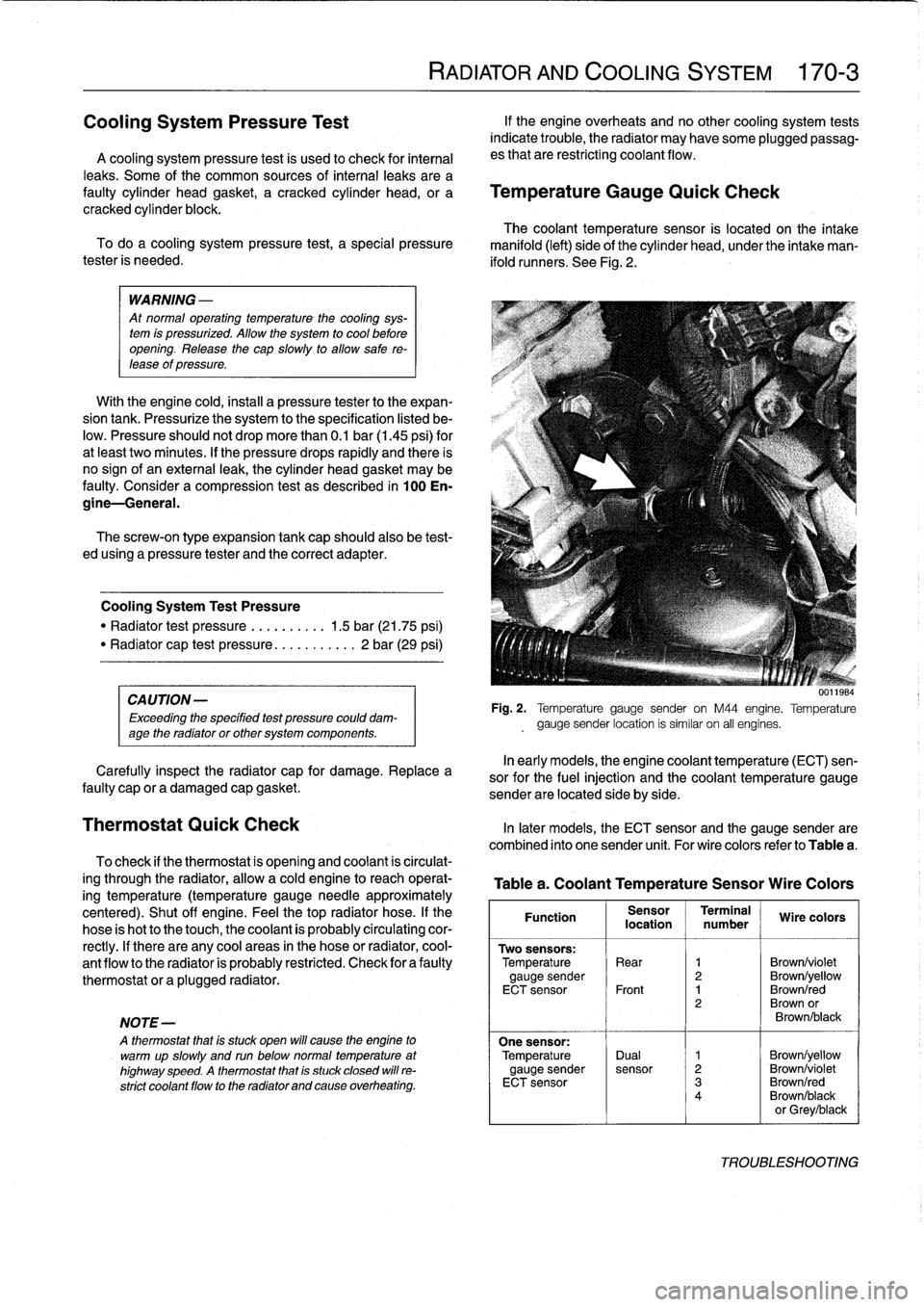
The
coolant
temperature
sensor
is
located
on
the
intake
To
doa
cooling
system
pressure
test,
a
special
pressure
manifold
(left)
side
of
the
cylinder
head,
under
the
intake
man-
tester
is
needed
.
ifold
runners
.
See
Fig
.
2
.
WARNING
-
At
normal
operating
temperature
-
the
cooling
sys-
tem
is
pressurized
.
Allow
the
system
to
cool
before
opening
.
Release
the
cap
slowly
to
allow
sale
re-
tease
of
pressure
.
With
the
engine
cold,instan
a
pressure
tester
to
the
expan-
sion
tank
.
Pressurize
thesystem
to
the
specification
listed
be-
low
.
Pressure
should
not
drop
more
than
0
.1
bar
(1
.45
psi)
for
at
leakt
two
minutes
.
If
the
pressure
drops
rapidly
and
there
is
no
sign
of
an
externa¡
leak,
the
cylinder
head
gasket
may
be
faulty
.
Considera
compression
test
as
described
in
100
En-
gine-General
.
The
screw-on
type
expansion
tank
cap
should
also
be
test-
ed
using
a
pressure
tester
and
the
correct
adapter
.
Cooling
System
Test
Pressure
"
Radiator
test
pressure
.........
.
1
.5
bar
(21
.75
psi)
"
Radiator
cap
test
pressure
..
.
........
2
bar
(29
psi)
CA
UTION-
Exceeding
the
speclfied
test
pressure
could
dam-
age
the
radiatoror
other
system
components
.
Carefully
inspect
the
radiator
cap
for
damage
.
Replace
a
faulty
cap
or
a
damaged
cap
gasket
.
Thermostat
Quick
Check
In
later
models,
the
ECT
sensor
and
the
gauge
sender
are
combined
into
one
sender
unit
.
For
wire
colors
refer
to
Table
a
.
To
check
if
the
thermostat
is
opening
and
coolant
is
circulat-
ing
through
the
radiator,
allow
a
cold
engine
to
reach
operat-
ing
temperature
(temperature
gauge
needieapproximately
centered)
.
Shut
off
engine
.
Feel
the
top
radiator
hose
.
If
the
hose
is
hot
to
the
touch,
the
coolant
is
probably
circulating
cor-
rectly
.
If
there
are
any
cool
areas
in
the
hose
or
radiator,
cool-
ant
flow
to
the
radiator
is
probably
restricted
.
Check
for
a
faulty
thermostat
or
aplugged
radiator
.
NOTE-
A
thermostat
that
is
stuck
open
will
cause
the
engine
to
warmup
slowly
and
run
belownormal
temperature
at
highway
speed
.
A
thermostat
that
is
stuck
closed
will
re-
strict
coolant
flow
to
the
radiator
and
cause
overheating
.
RADIATOR
AND
COOLING
SYSTEM
170-
3
U
.¡ig
.v
Fig
.
2
.
Temperature
gauge
sender
on
M44
engine
.
Temperature
gauge
sender
location
is
similar
on
al]
engines
.
In
early
models,
the
engine
coolant
temperature
(ECT)
sen-
sor
for
the
fuel
injection
and
the
coolant
temperature
gauge
sender
are
located
side
by
side
.
Table
a
.
Coolant
Temperature
Sensor
Wire
Colors
Function
Sensor
Terminal
Wire
colors
location
number
Two
sensors
:
Temperature
Rear
1
Brown/violet
gauge
sender
2
Brown/yellow
ECT
sensor
Front
1
Brown/red
2
Brown
or
Brown/black
One
sensor
:
Temperature
Dual
1
Brown/yellow
gauge
sender
sensor
2
Brown/violet
ECT
sensor
3
Brown/red
4
Brown/black
or
Grey/black
TROUBLESHOOTING
Page 199 of 759
NOTE-
Some
cars
covered
by
this
manual
may
have
an
alter-
nate
cooling
fan
switchwith
switching
temperatures
of
176%190W
(80%88°C)
.
When
replacing
the
switch
check
theswitching
specifications,
whichshouldbe
stamped
on
the
switch
body
.
1
.
If
coolant
is
circulating
at
normal
operating
tempera-
ture,
but
auxiliary
cooling
fan
does
not
run,
disconnect
connector
from
radiator
temperature
switch
and
make
tests
listed
in
Table
c
.
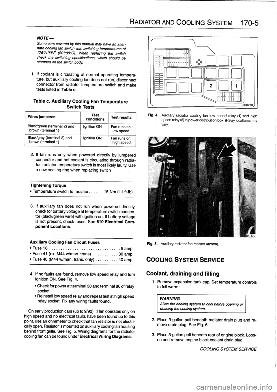
Table
c
.
Auxiliary
Cooling
Fan
Temperature
Switch
Tests
Wires
jumpered
Test
Test
resuits
conditions
Black/green
(terminal2)
and
Ignition
ON
Fan
runs
on
brown
(terminal
1)
low
speed
Black/gray
(terminal
3)
and
Ignition
ON
Fan
runson
brown
(terminal
I
1)
high
speed
2
.
If
fan
runs
only
when
powered
directly
by
jumpered
connector
and
hot
coolant
is
circulating
through
radia-
tor,
radiator
temperature
switch
is
most
likelyfaulty
.
Use
a
new
sealing
ring
when
replacing
switch
Tightening
Torque
"
Temperature
switch
to
radiator
......
15
Nm
(11
ft-Ib)
3
.
If
auxiliary
fan
does
notrun
when
powered
directly,
check
for
battery
voltage
at
temperature
switch
connec-
tor
(black/green
wire)
with
ignition
on
.
If
battery
voltage
is
not
present,
check
fuses
.
See
610
Electrical
Com-
ponent
Locations
.
RADIATOR
AND
COOLING
SYSTEM
170-
5
~r~nmm
a
00
0
Fig
.
4
.
Auxiliary
radiator
cooling
fan
low
speed
relay
(1)
and
high
speed
relay
(2)
in
power
distribution
box
.
(Relay
locations
may
vary
.)
Auxiliary
Cooling
Fan
Circuit
Fuses
Fig
.
5
.
Auxiliary
radiator
fan
resistor
(arrow)
.
"
Fuse16
.
...................
..
..
...
...
.5
amp
"
Fuse
41
(ex
.
M44
w/man
.
trans)
.
..
.
..
.....
30
amp
"
Fuse
48
(M44
w/man
.
trans
.
only)
..
.
..
.....
40
amp
COOLING
SYSTEM
SERVICE
0013034
4
.
If
no
faults
are
found,
remove
low
speed
relay
and
turn
Coolant,draining
and
filling
ignition
ON
.
See
Fig
.
4
.
1
.
Remove
expansion
tank
cap
.
Set
temperature
controls
"
Check
for
power
at
terminal
30
and
terminal
86
of
relay
to
full
warm
.
socket
.
"
Reinstall
low
speed
relay
and
repeat
testat
high
speed
WARNING
-
relay
socket
.
Fix
any
wiring
faults
found
.
Allow
the
cooling
system
to
cool
before
openlng
or
On
early
productioncars
(up
to
9/92)
:
If
fan
operates
only
on
draining
the
cooling
system
.
high
speed
and
no
electrical
faults
have
been
foundup
to
this
point,
usean
ohmmeter
to
check
that
fan
resistor
is
not
electri-
2
.
Place
3
ra
allo
ug
.
beneath
radiator
drain
plug
and
re-
cally
open
.
Resistor
is
mounted
on
auxiliary
cooling
fan
housing
move
drain
plg
.
See
Fig
.
6
.
behind
front
grille
.
See
Fig
.
5
.
Wiring
diagrams
for
the
radiator
cooling
fan
canbefoundunder
Electrical
Wiring
Diagrams
.
3
.
Place
3-g
pail
beneath
rear
of
engine
blo
.
Loos-
en
and
re
mlon
ove
engine
blockcoolant
drain
plug
k
.
COOLING
SYSTEM
SERVICE
Page 386 of 759
00-
6
ELECTRICAL
SYSTEM-GENERAL
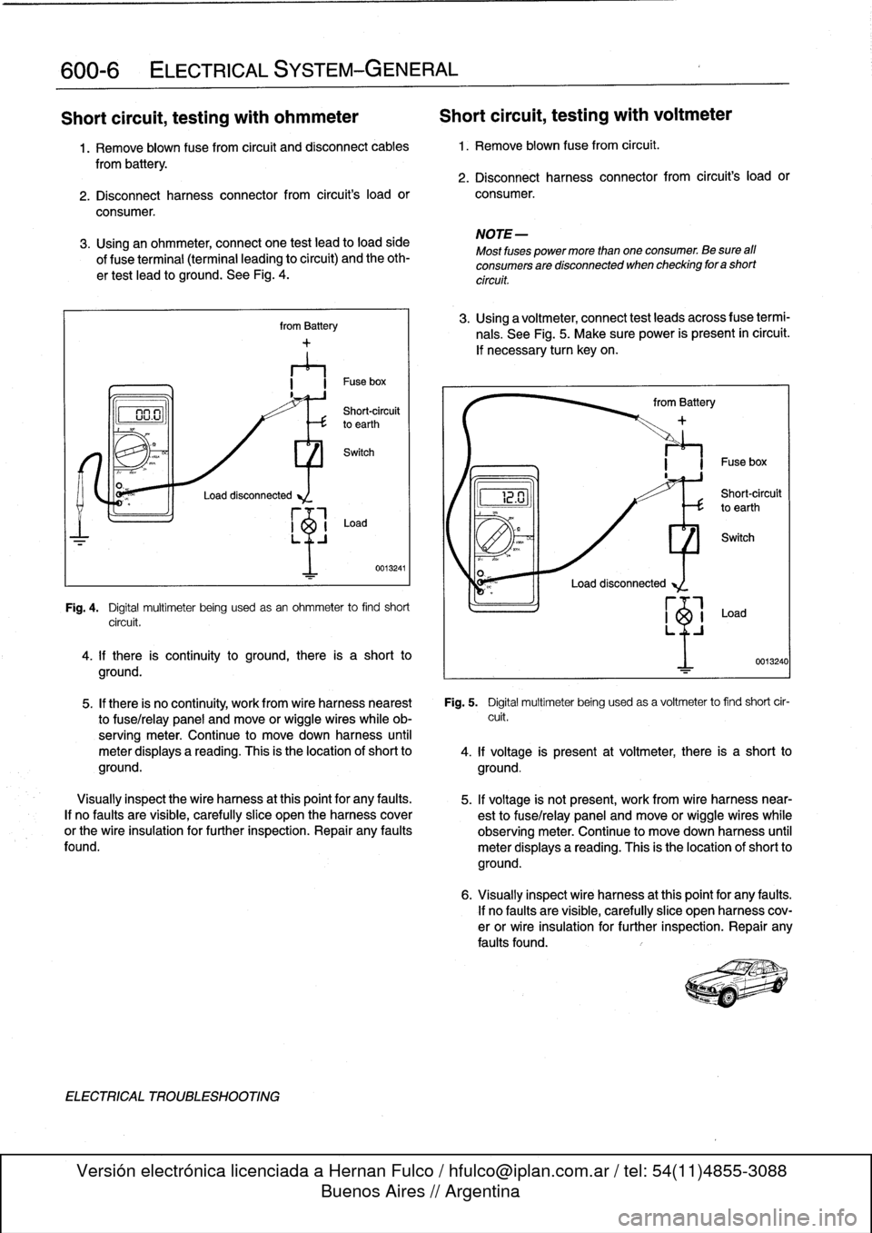
Short
circuit,
testing
with
ohmmeter
Short
circuit,
testing
with
voltmeter
1
.
Remove
blown
fuse
from
circuit
and
disconnect
cables
1
.
Remove
blown
fusefrom
circuit
.
from
battery
.
2
.
Disconnect
harness
connector
from
circuifs
loador
2
.
Disconnect
harness
connector
from
circuit's
loador
consumer
.
consumer
.
3
.
Using
an
ohmmeter,
connect
one
test
lead
to
loadside
of
f
use
terminal
(terminal
leading
to
circuit)
and
the
oth-
ertest
lead
to
ground
.
See
Fig
.
4
.
Load
disconnected
from
Battery
LO
n
I
~
Shotrouit
vu
.uto
earthth
Switch
Load
0013241
Fig
.
4
.
Digital
multimeter
being
usedasan
ohmmeter
to
find
short
circuit
.
4
.
lf
there
is
continuity
to
ground,
there
is
a
short
to
ground
.
ELECTRICAL
TROUBLESHOOTING
NOTE-
Most
fuses
power
more
than
one
consumer
.
Be
sure
aff
consumers
are
disconnected
when
checking
for
a
short
circuit
.
3
.
Using
a
voltmeter,
connect
test
leads
across
f
use
termi-
nals
.
See
Fig
.
5
.
Make
sure
power
is
present
ín
circuit
.
lf
necessary
turn
keyon
.
~2
.U
from
Battery
Load
disconnected
Short-circuit
to
earth
I
Fuse
box
0013240
5
.
If
there
is
no
continuity,
work
from
wire
harness
hearest
Fig
.
5
.
Digital
multimeter
being
usedas
a
voltmeter
to
find
short
cir
to
fuse/relay
panel
and
move
or
wiggle
wireswhile
ob-
cuit
.
serving
meter
.
Continue
to
movedown
harness
until
meter
displays
a
reading
.
This
is
the
location
of
short
to
4
.
lf
voltage
is
present
at
voltmeter,
there
is
a
short
to
ground
.
ground
.
Visually
inspect
the
wire
harness
at
this
point
for
any
faults
.
5
.
lf
voltage
is
not
present,
work
from
wire
harness
near-
If
no
faults
are
visible,
carefully
slice
open
the
harnesscover
est
to
fuse/relay
panel
and
move
orwiggle
wireswhile
or
the
wire
insulation
for
further
inspection
.
Repair
any
faults
observing
meter
.
Continue
to
move
down
harness
until
found
.
meter
displays
a
reading
.
This
is
the
location
of
short
to
ground
.
6
.
Visually
inspect
wire
harness
atthis
point
for
any
faults
.
lf
no
faults
are
visible,
carefully
slice
open
harness
cov-
erorwire
insulation
for
further
inspection
.
Repair
any
faults
found
.
Page 701 of 759

ELE-218
ELECTRICAL
WIRING
DIAGRAMS
ANTI-THEFT
CONTROL
MODULE
104823
NOT
AT
HOT
IN
RUN,
NOT
IN
RUN
.
ALLTIMES
__
_
FUSE
ACCVANDSTART
ACCYANDSTART
I
-__---________________________-_________--
FUSE
FUSE
(
FRONTER
I
F33
F43
F41
(DISTRIBUTION
I
t0A
5A
15A
SOX
X10019
2F
x3Do1B
zS
Xloo1
.e
RED/
'ol
Viol
WHT
WHT
BLK
Interior
Lights/Illumination
1998Except
318ti
&
Convertible
V
I01
WHT
READING
LIGHTS
WHT
I
R
BLK
(
RED
I
BRN
OFF
viol
WHTFRONTDOME
LIGHT/
MAP
READING
ASSEMBLY
WIREAR
y
READING
LIGHTS
RED/
REII
WHT
I
WHT
I
R
BLK
I
RBLK
_~
R
BLK
I
RED
I
WHT
I
BEN4
I
WH0FL
1
F
WI
READ
NGMP
BRN/
WHT
TRUNK
COMPARTMENT
LIGHT
LEFT
RIGHT
LEFT
FRONT
FRONT
REAR
ROOTWELL
FOOTWELL
INTERIOR
LIGHT
LIGHT
LIGHT
BRNI
BRN
BRN
BRN
BR
N1
BRN
F-W/READNIGLMPP
BFN
I
BRN
I
SRN
I
t11
G203
G312
G310
BRN/WHT
"
w
RIGHT
REAR
INTERIOR
LIGHT
viol
V10/
WHT
I
WNT
DRIVER'S
~`
PASSENGER'S
MAKEUP
/~
MAKEUP
VIO/
MIRROR
/\
~(~~/~MIRROR
BILK
LIGHT
I
~/
LIGHT
I
I
I~~
'
~
J,
.~~
GLOVE
BRN'
BRN,
I
~t
(BOX
.
./LLl'~l/~C~'/\I~
LIGHT
SWITCH
DRIVER'S
PASSENGER'S
MAKEUP
MAKEUP
MIRRORMIRROR
[
't
]
SWITCH
SWITCH
BRN
I
BFN
REO/
ED/
WHTK
12t
:
-=
tx13252
.
BODY
ELECTRONICS
I
I
CONTROL
I
_I
MODULE
__
------__--=c--___-GCCCC-__--ccc-__
_
_-------__--
(ZKEIV)
16
2
3
1
SI
q
BRN/I
BRN/I
BRN/
WHT
GRV/VELBLU/VEL
_
_
BRN/WHT
:
I
I
/ANTI-
I
W/OANTI-
T(-
I
W/ANTI-
1
111
BRN/WHT
/
THEFT
THEFT
THEFT
^
THEFT
I
INSTRUMENT
I
I
~4
BRN/GRV/VEL
I
"
BRN/GRVIVEL
CLUSTER
BRN/
I
BRN/
I`
BRN/
I
GRN/
I`
I
I
15
BRN/BLU/VEL
I
SYSTEM
WHT
WHT
BLK
WHT/VEL
I
I
ISB
WHT
1
=
L-
J
BFNI
WHT
I
GRVS/VEL
BNf
I
BLU/VEZ
I
WHZ
l
WH2
I
WNT
I
S
BLK
//
~
WNT/VEZ
I
WHT
VE9
lll
111/
~~~
Jll
/'
...
TRUNK
DRIVER'S
PASSENGER'S
LEFT
RIGHTRIGHT
LEFT
CONVERTIBLETRUNK
LIGHT
DOOR
DOOR
REAR
REAR
REAR
REAR
TOP
II
LIO
[~A
SWITCH
SWITCHSWITCH
CONTACTCONTACT
S4V
MO
TCH
SWITCHSW
MICRO
ITCHSLID
I
-I
RELAY
tY
1Y
,Y
-
--
1Y
0RN'
BR"'
IRI
ISBN
SPIN
I
.FN
I
-FN
I
BFN
I
BRN
G3121
(2pOOR)
G2031G310
(4000R)
1
Z
Page 753 of 759
4
INDEX
Evaporator
See
Air
conditioning
EWS
(Electronic
immobilization
system)
515-8
Exhaust
system
See
also
Maintenance
program
general
information
180-1
exhaust
manifolds,
removingAnstalling
180-5
exhaustsystem,
removing/installing
180-3
Expansion
valve
See
Air
conditioning
Exterior
lighting
general
information
630-1
center
brake
light
housing,
replacing
(4-door
and
coupe
models)
630-5
foglight
assembly,
removing/installing
630-3
front
turn
signal
assembly,
removing/
installing
630-4
headlight
assembly,removing/
installing
630-2
headlight
bulb,
replacing
630-1
license
plate
light,
removing/installing
630-6
side
marker
lights
630-4
taillight
assembly,
removing/installing
630-5
taillight
bulbs,
replacing
630-4
Exterior
trim,
bumpers
general
information
510-1
BMW
embiem,
removing/installing
510-7
body
side
molding,
replacing
-7
bumper
height,
adjusting
510-6
front
bumper,
removing/installing
510-3
front
bumper
impact
absorber,
replacing
510-4
front
panel,
removing/installing
510-7
outside
rear
view
mirrors
510-1
mirror
housing,
removing/installing
510-1
mírror,
removing/installing
510-2
mirror
glass,
replacing
510-1
radiator
grille,
removing/installing
510-7
rear
bumper,
removingfinstalling
510-
4
rear
bumper
impact
absorber,
replacing
510-4
F
Fenders,
engine
hood
general
information
410-1
front
fenders
410-1
front
fender,
removing/installing
410-1
hood
aligning
410-4
hood,
raising
to
service
position
410-2
hood
release
cable
and
latches,
adjusting
410-4
hood,
removing/installing
410-3
Finaldrive
general
information
331-1
final
drive
se
rvice
331-1
flange
oil
sea¡,
replacing
331-2
inputshaft
oil
sea¡,
replacing
331-3
oil,
draining/filling
331-1
oil
seals331-1
removing/installing
331-3
Final
drive
carrier
See
Rear
suspension
Firing
order
See
Ignition
system
Flexdisc
See
DriveshaftFluids
and
lubricants
See
Maintenance
program
Foglight
See
Exterior
lighting
Front
suspension
general
information
310-1
ball
joint
See
outer
control
arm
ball
joint
control
arm,
removing/installing
310-5
control
arm
bushing,
replacing
310-7
control
arms
310-5
front
wheel
bearing,
replacing
310-8
front
wheel
bearings
310-8
outer
control
arm
ball
joint,
replacing
(except
M3)310-6
ride
height
310-4shock
absorbers
and
springs
310-2
stabilizer
bar
310-9
stabilizer
bar,
removing/installing
310-9
strut
assembly,disassembling/
assembling310-4
strut
assembly,
removing/installing
310-2subframe
crossmember
310-9subframe
crossmember,
removing/
installing
310-9
Fuel
injection
general
information
130-2
basic
engine
settings
130-2
principies
of
operatínn
130-2
Bosch
DME
Ml
.7
component
tests
and
repairs
130-14
air
floiv
sensor,testing/replacing
130-14
engine
coolant
temperature
(ECT)
sensor,
testing/replacing
130-15
¡dle
speed
control
valve,
testing/
replacing
130-16
throttle
position
sensor
(TPS),
testing/replacing
130-16
Bosch
DME
M3
.1
and
M3
.3
.1
component
tests
and
repairs
130-17
engine
coolant
temperature
(ECT)
sensor,
testing/replacing
130-18
¡dle
speed
control
valve,
replacing
130-21
¡dle
speed
control
valve,
testing
130-
20
intake
air
temperature
(IAT)
sensor,
testing/replacing
130-19
mass
air
flow
sensor130-17
Bosch
DME
M3
.1
and
M3
.3.1
(cont)
mass
air
flow
sensor
(hot
film)
testing/replacing
130-18
mass
air
flow
sensor
(hot
wire)
testing/replacing
130-17
throttle
position
sensor
(TPS),
testing/replacing
130-19
Bosch
DME
M5
.2
component
replacement
130-21engine
coolant
temperature
(ECT)
sensor,
replacing
130-22
ldle
speed
control
valve,
replacing
130-23
intake
air
temperature
(IAT)
sensor,
replacing
130-22
mass
air
flow
sensor,
replacing
130-
22
throttle
position
sensor
(TPS),
replacing
130-22
DISA
(dual
resonance
intake
system)
130-3
ECM
pin
assignments130-26
electrical
checks
andcomponent
testing
130-7engine
control
module(ECM),
accessing
130-26
fuel
delivery
tests
130-9
fuel
pressure
regulator
response
to
engine
load,
testing
130-11
fuel
pressure
regulator
130-13
fuel
pressure
regulator,
replacing
(fuel
rail
mount)130-13
fuel
pressure
regulator,
replacing
(under
car
mount)130-14
fuel
pump
relay,
testing
130-7
fuel
rail
and
injectors,
checking
130-11
fuel
rail
and
injectors,
replacing
130-
12
fuel
delivery
tests
(cont
.)
operatíng
fuel
pump
for
tests
130-9
relieving
fuel
pressure
and
connecting
fuel
pressure
gauge
130-10
residual
fuel
pressure,
testing
130-10
main
relay,
testing
130-7on-board
diagnostics
(OBD)
and
fault
diagnosis
130-4
oxygen
sensor,
testing
(Bosch
systems
only)
130-8
secondary
air
injection
130-5
Siemens
MS
41
.1
component
replacement
130-23
engine
coolant
temperature
(ECT)
sensor,
replacing
130-25
¡dle
speed
control
valve,
replacing
130-26
lntake
air
temperature
(IAT)
sensor,
replacing
130-25
mass
air
flow
sensor,
replacing
130-
25
throttle
position
sensor
(TPS),
replacing
130-26warnings
and
cautions
130-6
Fuel
filter
See
Maintenance
program