hot wire BMW 325i 1992 E36 Workshop Manual
[x] Cancel search | Manufacturer: BMW, Model Year: 1992, Model line: 325i, Model: BMW 325i 1992 E36Pages: 759
Page 7 of 759
Please
read
these
warnings
and
cautions
before
proceeding
with
maintenance
and
repair
work
.
WARNING-
"
Friction
materials
(such
as
brake
pads
or
shorts
or
clutchdiscs)
contain
asbestos
fibers
or
other
friction
materials
.
Do
notcreate
"
See
also
Cautionson
page
viü
dustby
grinding,
sanding,
orby
cleaning
with
compressed
air
.
"
Some
repairs
may
be
beyond
your
capability
.
If
you
lack
the
Avoid
breathing
dust
.
Breathing
any
friction
material
dust
can
lead
skills,
tools
and
equipment,
or
a
suitable
workplace
for
any
proce-
to
serious
diseases
and
may
result
in
death
.
duredescribed
in
this
manual,
we
suggestyou
leave
such
repairs
"
Batteries
give
off
explosive
hydrogen
gas
during
charging
.
to
an
authorized
BMW
dealer
service
department
or
other
quali-
Keep
sparks,
lighted
matches
and
open
flame
away
from
the
top
fied
shop
.
of
the
battery
If
hydrogen
gas
escaping
from
the
cap
vents
is
"Do
not
re-use
any
fasteners
that
are
worn
or
deformed
in
normal
ignited,
it
will
ignite
gas
trapped
in
the
cells
and
cause
the
battery
use
.
Many
fasteners
are
designed
to
be
used
only
once
and
to
explode
.
become
unreliable
and
may
fail
when
used
a
second
time
.
This
"
Connect
and
disconnect
battery
cables,
jumper
cablesora
bat-
includes,
but
is
not
limited
to,
nuts,
bolts,
washers,
self-locking
nuts
or
bolts,
circlips
and
cotterpins
.
Always
replace
these
fasteners
with
new
parts
.
"Do
not
quick-charge
the
battery
(for
boost
starting)
for
longer
"
Never
work
under
a
lifted
car
unless
it
is
solidly
supportedon
than
one
minute
.
Wait
at
least
one
minute
before
boosting
the
bat-
stands
designed
for
the
purpose
.
Do
not
support
a
car
on
cinder
tery
a
second
time
.
blocks,
hollow
tiles
or
other
props
that
may
crumble
under
contin-
uous
load
.
Never
work
under
acar
that
is
supported
solely
by
a
"Do
not
allow
battery
charging
voltage
to
exceed
16
.5
volts
.
If
the
jack
.
Never
work
under
thecar
while
the
engine
is
running
.
battery
beginsproducing
gas
or
boiling
violently,
reduce
the
charg-
ing
rate
.
Boosting
a
sulfated
battery
at
a
high
charging
rate
can
"
If
you
are
going
to
work
under
acar
on
the
ground,
make
sure
cause
an
explosion
.
that
the
ground
is
level
.
Block
the
wheels
to
keep
the
carfrom
roll-
ing
.
Disconnect
the
battery
negative
(-)
terminal
(ground
strap)to
"
The
air-conditioning
system
is
filled
with
chemical
refrigerant,
prevent
others
from
starting
thecar
while
youare
under
it
.
which
is
hazardous
.
TheA/C
system
should
be
servicedonly
by
trained
technicians
using
approved
refrigerant
recovery/recycling
"
Never
run
the
engine
unless
the
work
area
is
well
ventilated
.
equipment,
trained
in
related
safetyprecautions,
and
familiar
with
Carbon
monoxide
kills
.
regulations
governing
the
discharging
and
disposal
of
automotive
"
Finger
rings,
bracelets
and
other
jewelry
shouldbe
removed
so
chemical
refrigerants
.
tery
charger
only
with
the
ignition
switched
off,
to
prevent
sparks
.
Do
not
disconnect
the
battery
while
the
engine
is
running
.
that
theycannot
cause
electrical
shorts,
get
caught
in
running
"
Do
not
expose
any
partof
the
A/Csystem
to
high
temperatures
machinery,
or
be
crushed
by
heavy
parts
.
suchas
open
flame
.
Excessiveheat
will
increase
system
pressure
"
Tie
long
hair
behind
your
head
.
Do
not
wear
a
necktie,
a
scarf,
and
may
cause
the
system
to
burst
.
loose
clothing,
or
a
necklace
when
you
work
near
machine
tools
or
"
Some
aerosol
tire
inflators
are
highly
flammable
.
Be
extremely
running
engines
.
If
your
hair,
clothing,
or
jewelry
were
to
get
caught
cautious
when
repairing
a
tire
that
may
havebeen
inflated
using
in
the
machinery,
severe
injury
could
result
.
an
aerosol
tire
inflator
.
Keep
sparks,
open
flame
or
other
sources
"
Do
not
attempt
to
work
onyourcar
if
you
do
not
feel
well
.
You
of
ignition
away
from
the
tire
repair
area
.
Inflate
and
deflate
the
tire
increase
the
danger
of
injury
toyourself
and
others
if
you
are
tired,
at
least
four
times
before
breaking
the
bead
from
therim
.
Com-
upset
or
have
takenmedication
or
any
other
substance
that
may
Pletely
remove
the
tire
from
the
rim
beforeattempting
any
repair
.
keep
you
from
being
fully
alert
.
"
Illuminate
your
work
areaadequately
but
safety
.
Use
a
portable
safety
light
for
working
inside
or
under
thecar
.
Make
surethe
bulb
is
enclosedbya
wire
cage
.
The
hot
filament
of
an
accidentally
bro-
ken
bulb
can
ignite
spilled
fuel
or
oil
.
"
Catch
draining
fuel,
oil,
orbrake
fluid
in
suitable
containers
.
Do
not
use
food
or
beverage
containers
that
mightmislead
someone
into
drínking
from
them
.
Store
flammable
fluids
away
from
fire
haz-
ards
.
Wipe
up
spills
at
once,
but
do
not
store
the
oily
rags,
which
can
ignite
and
burn
spontaneously
.
"
Always
observe
good
workshop
practices
.
Wear
goggles
when
youoperate
machine
tools
or
work
with
battery
acid
.
Gloves
or
other
protectioeclothing
should
be
worn
whenever
thejob
requires
working
with
harmful
substances
.
"
Greases,
lubricants
and
other
automotive
chemicals
contain
toxic
substances,
many
of
which
are
absorbed
directly
through
the
skin
.
Read
the
manufacturer's
instructions
and
warnings
carefully
.
Use
hand
andeye
protection
.
Avoid
direct
skin
contact
"
Cars
covered
by
this
manual
are
equipped
with
a
supplemental
restraint
system
(SRS),
that
automatically
deploys
an
airbag(s)
in
theevent
of
a
frontal
ímpact
.
The
airbag(s)
is
inflated
byan
explo-
sive
device
.
Handled
improperly
or
without
adequate
safeguards,
can
be
accidently
activated
and
cause
serious
injury
.
"
The
ignition
system
produces
high
voltages
that
can
be
fatal
.
Avoid
contact
with
exposed
terminals
and
use
extreme
care
when
working
ona
car
with
the
engine
running
or
the
ígnition
switched
on
.
"
Place
jack
stands
only
at
locations
specified
bymanufacturer
.
The
vehicle
lifting
jacksupplied
with
the
vehicle
is
intended
for
tire
changes
only
.
A
heavy
duty
floor
jack
shouldbe
used
to
lift
vehicle
before
installing
jack
stands
.
See
010
Fundamentals
for
theDo-
.
it-Yourself
Owner
.
"
Battery
acid
(electrolyte)
can
cause
severeburns
.
Flush
contact
area
with
water,
seek
medical
attention
.
"
Aerosolcleaners
and
solvents
may
contain
hazardous
ordeadly
vapors
and
are
highly
flammable
.
Use
only
in
a
wellventilated
area
.
Do
not
use
on
hot
surfaces
(engines,
brakes,
etc
.)
.
"
Disconnect
the
battery
negative
(-)
terminal
(Ground
strap)
"
Do
not
remove
coolant
reservoir
or
radiator
cap
with
theengine
whenever
you
work
on
the
fuel
system
orthe
electrical
system
.
Do
hot
.
Danger
of
bums
and
engine
damage
.
not
smoke
or
work
near
heaters
or
other
fire
hazards
.
Keep
an
approved
fire
extinguisher
handy
.
continued
on
next
page
vii
Page 116 of 759
119-2
LUBRICATION
SYSTEM
NOTE-
Component
Location
If
the
light
does
not
go
out,
thewiring
to
theswitch
is"
Oil
pressure
switch
most
likely
grounded
somewhere
between
the
switch
all
engines
.......
...
.
..
......
ora
oil
filter
housing
terminal
and
the
warning
light
.
Sea
Electrical
Wiring
Diagrams
atrearof
manual
for
electrical
schematics
.
CAUTION-
Some
oil
may
drain
out
as
the
oil
pressure
switch
is
removed
.
Use
a
rag
to
soak
up
any
spills
.
2
.
Install
pressure
gauge
in
place
of
switch
.
3
.
With
gauge
instalied,
start
engine
and
allow
to
reach
operating
temperature
.
Check
oil
pressureboth
cold
and
hot
.
NOTE-
For
the
most
accurate
test
results,
the
engine
oil
(and
filter)
shouldbe
newand
of
the
correct
grade
.
Oil
Pressure
"
¡dle
(mínimum)
..
.
.
..............
.
.
0
.5
bar
(7psi)
"
Regulated
pressure
(elevated
engine
speed)
4-cylinder
engines
..
......
4
.3
±
0
.2
bar
(63
t3
psi)
6-cylinder
engines
.
.
.............
.
4
.0
bar
(59
psi)
4
.
Remove
pressure
gauge
and
reinstall
pressure
switch
.
If
testing
shows
low
oil
pressure,
one
or
more
of
the
follow-
ing
conditions
may
be
indicated
:
OIL
PAN
"
Worn
or
faulty
oii
pump
.
"
Worn
or
faulty
engine
bearings
The
oil
pancan
be
removed
with
the
engine
instalied,
al-
Severe
engine
wear
.
though
specíal
enginesupport
equipment
will
be
needed
.
Al¡
of
these
conditionsindicate
the
need
for
major
repairs
.
Oil
pressure
warning
system,
testing
When
the
ignition
is
tumed
ora,
the
oil
pressure
warning
light
comes
ora
.
When
the
engine
ís
started
and
the
oil
pressure
ris-
es
slightly,
the
oil
pressure
switch
opens
and
thewarning
light
goes
out
.
Make
sure
the
oil
leve¡
is
correct
before
making
tests
.
1
.
Turra
ignition
switch
ora
.
"
Warning
light
ora
instrument
panel
must
light
up
.
2
.
Remove
connector
from
oil
pressure
switch
.
"
Warning
light
ora
instrument
panel
must
go
out
.
OIL
PAN
3
.
If
warning
light
does
not
light
when
ignition
is
ora,
re-
move
connector
from
oil
pressure
switch
anduse
a
jumper
wire
to
ground
connector
terminal
to
a
clean
metal
surface
.
NOTE
-
If
the
warning
light
comes
ora,
check
the
switch
as
de-
scríbed
in
the
nextstep
.
If
the
warning
light
does
not
come
ora,
thewiring
to
the
instrument
cluster
or
to
the
light
itself
isfaulty
.
4
.
To
test
switch,
connect
ara
ohmmeter
between
terminal
in
switch
body
and
ground
.
With
engine
off,
these
should
be
continuity
.
With
engine
running,
oil
pressure
should
opera
switch
and
there
should
beno
continuity
Replace
a
faulty
switch
.
WARNING
-
Keep
in
mind
that
low
oil
pressure
may
be
prevent-
ing
the
switch
from
tuming
the
light
out
.
If
the
light
remains
ora
while
the
engine
is
running,
check
the
oil
pressure
asdescribed
earlier
.
Do
not
drive
the
car
until
the
problem
is
corrected
.
Theengine
may
be
severely
damaged
.
Oil
pan,
removing
and
installing
(4-cylinder
engines)
1
.
Raise
car
arad
place
securely
ora
jackstands
.
2
.
Remove
splash
shíeld(s)
from
under
engine,
where
ap-
plicable
.
3
.
Drain
engine
oil
as
described
in
020
Maintenance
Pro-
gram
.
4
.
Disconnect
vacuum
hose
adapter
from
vacuum
brake
booster
at
rear
of
engine
compartment
.
5
.
Remove
oil
dipstick
guide
tube
mounting
nut
and
pull
guide
tube
from
oil
pan
.
See
Fig
.
2
.
Page 147 of 759
GENERAL
.
.
.
.
.
.
.
.
.
...
.
.
.
.
.
.
.
.........
130-2
Intake
air
temperature
(IAT)
sensor,
Principles
of
Operatinn
.
.
.
.
.
.
.
.
.
.........
130-2
testing
and
replacing
...
.
...
.
.
.
.......
.
130-19
Basic
Engine
Settings
.
.
.
.
.
.
.
.
.
.
.
.
.
.
...
:
.
130-3
Throttle
position
sensor
(TPS),
DISA
(Dual
Resonance
Intake
System)
.
.
.
.
.
130-3
testing
and
replacing
...
.
...
.
.
.
.
.
...
.
.
.130-19
On-Board
Diagnostics
(OBD)
Idle
speed
control
valve,
testing
.
.
.
.
.
.
.
.
.
.
130-20
and
Fault
Diagnosis
.
.
....
.
......
.
.
.
...
130-4
Idle
speed
control
valve,
replacing
.
.
.
.
.
.
..
130-21
SecondaryAir
Injection
.
.
.....
.
.........
.
130-5
BOSCH
DME
M5
.2
COMPONENT
Warnings
and
Cautions
.
.
...
.
.
.
.........
.
130-6
REPLACEMENT
.....
.
......
.
....
.
.
.
..
130-21
ELECTRICAL
CHECKSAND
Mass
air
flow
sensor,
replacing
.
.
....
.
....
130-22
COMPONENT
TESTING
.
.
.
.
.
.
.
.
...
.
.
.
.
.
130-7
Engine
coolant
temperature
(ECT)
Main
sensor,
replacing
..
.
.
.
.
.
.
.
.
.
.
.
.
.
.
.
.
.
.
130-22
rela
y
testing
130
-7
,...
.
.
.
.
.
.
.
.
.
...
.
.
.
.
.
.
.
Intake
air
temperature
(IAT)
sensor,
Fuel
pump
relay,
testing
.
.
.
.
.
.
.
...
.
.
.
.
.
.
.
130-7
rep
lacin
.
.
.
.
.
.
.
.
.
.
.g
.
.
.
.
.
.
.
...
.
.
.
..
.130-22
Oxygen
sensor,
testing
(Boschsystems
only)
130-8
Throttle
poson
sensor
(TPS)
replacing
13022
,
..
.-
FUEL
DELIVERY
TESTS
...
.
....
.
.
.
...
.
130-9
Idle
speed
control
valve,
replacing
...
.
....
.130-23
Operating
fuel
pump
for
tests
.
.
.......
.
...
130-9
SIEMENS
MS
41
.1
COMPONENT
Relieving
fuel
pressure
and
REPLACEMENT
.
...
.
.
.
.
.
.......
.
....
.130-23
connecting
fuel
pressure
gauge
......
.
..
130-10
Residual
fuel
pressure,
testing
.
.....
.
.
.
.
.
130-10
Mass
air
flow
sensor,
replacing
.
.......
.
.
.130-25
Fuel
pressure
regulator
response
Engine
coolant
temperature
(ECT)
to
engine
load,
testing
.
.
.
.
.
.
.
.
.
.
.
.
.
.
.
.
130-11
sensor,
replacing
.....
.
.
.
.
.
.........
.130-25
Fuel
rail
and
injectors,
checking
...
.
.
.
.
.
.
.
130-11
Intake
air
temperature
(IAT)
sensor,
replacing
.
.
.
.
.
.....
.
.
.
.
.
.
.
.......
.
.
.130-25
Fuel
rail
and
injectors,
replacing
..
.
.
.
.
.
.
.
130-12
Throttleposition
sensor
(TPS),
replacing
.
.
.
130-26
Fuel
PressureRegulator
.........
.
.
.
.
.
.
.
130-13
Idle
s
eed
control
valve,
re
lacin
130-26
Fuel
pressure
regulatorreplacing
p
p
g
.'''...
.
'
,
(fuel
rail
mount)
...
.
.
.
.
.
.............
130-13
ECM
PIN
ASSIGNMENTS
.............
.
.
130-26
Fuel
pressure
regulator,
replacing
Engine
control
module
(ECM),
accessing
...
130-26
(undercar
mount)
.
.
.
.
.
.
.
.
.........
.
.
130-14
BOSCH
DME
M1
.7
COMPONENT
TESTS
AND
REPAIRS
.
.
.
.
.
...
.
.
.
.
.
.
.
.
130-14
Air
flow
sensor,
testing
and
replacing
.
.
.
.
.
.
130-14
Engine
coolant
temperature
(ECT)
sensor,
testing
and
replacing
...
.
.
.
.
.
.
.
.
130-15
Throttle
position
sensor
(TPS),
testing
and
replacing
.
..........
.
.....
130-16
Idle
speed
control
valve,
testing
and
replacing
.
.
.
.
.
............
130-16
BOSCH
DME
M3
.1
AND
M33
.1
COMPONENT
TESTS
AND
REPAIRS
.
.
.
130-17
Mass
Air
Flow
Sensor
.
.
.
.
.
.
.
.
.....
.
.
.
.
.130-17
Mass
air
flow
sensor
(hotwire),testing
and
replacing
.
.
.
.
.
.....
.
.
.
.
.
.
.
130-17
Mass
air
flow
sensor
(hot
film),
testíng
and
replacing
.
.
.
.....
.
.
.
.
.
.
.
.
.
130-18
Engine
coolant
temperature
(ECT)
sensor,
testing
and
replacing
..
.
.
.
.
.
...
.
130-18
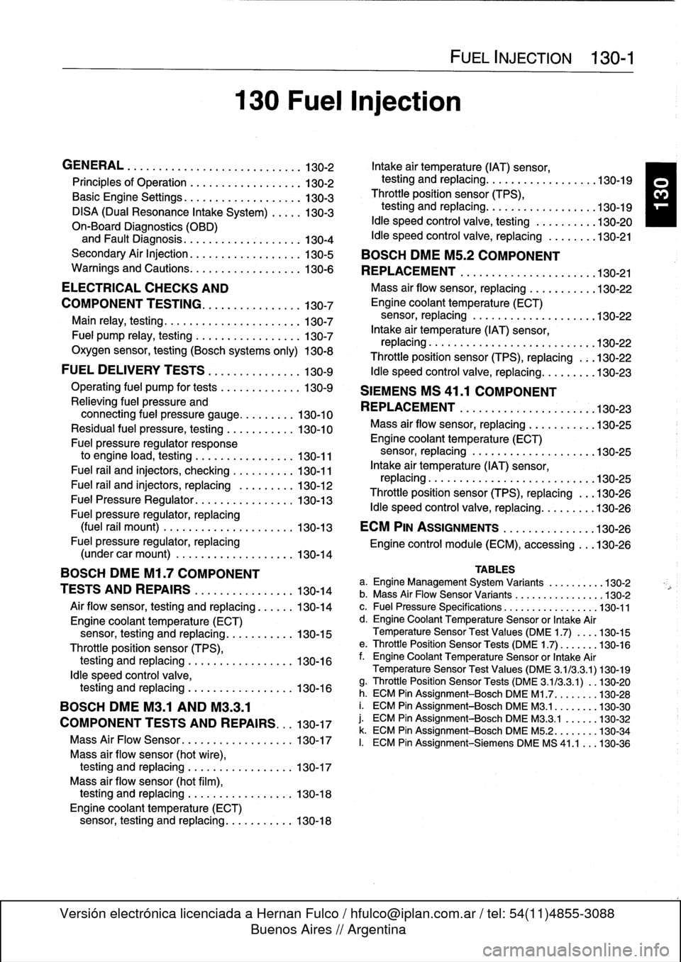
130
Fuel
i
n
jection
FUEL
INJECTION
130-1
TABLES
a
.
Engine
Management
System
Variants
.........
.130-2
b
.
Mass
Air
Flow
Sensor
Variants
..
.
..
..........
.130-2
c
.
Fuel
Pressure
Specifications
..
.
.
...
..........
130-11
d
.
Engine
Coolant
Temperature
Sensor
or
Intake
Air
Temperature
Sensor
Test
Values
(DME
1
.7)
...
.
130-15
e
.
ThrottlePosition
Sensor
Tests
(DME
1
.7)
......
.130-16
f
.
Engine
Coolant
Temperature
Sensor
or
Intake
Air
Temperature
Sensor
Test
Values
(DME
3
.1/3
.3
.1)130-19
g
.
Throttle
Position
Sensor
Tests
(DME
3
.1/3.3
.1)
.
.130-20
h
.
ECM
Pin
Assignment-Bosch
DME
M1
.7
....
.
..
.130-28
i.
ECM
Pin
Assignment-Bosch
DME
M3
.1
.......
.130-30
j
.
ECM
Pin
Assignment-Bosch
DME
M3
.3
.1
.....
.130-32
k
.
ECM
Pin
Assignment-Bosch
DME
M5
.2
.......
.
130-34
I.
ECM
Pin
Assignment-Siemens
DME
MS
41
.1
..
.
130-36
Page 148 of 759
130-2
FUEL
INJECTION
GENERAL
This
repair
group
covers
fuel
injection
system
component
testing
and
repair
.
Special
equipment
is
necessary
for
some
of
the
procedures
given
in
this
repair
group
.
If
you
do
not
have
the
equipment
required
to
do
the
job,
it
is
recommended
that
these
repairs
be
left
to
an
authorized
BMW
dealer
.
The
BMW
dealer
is
equipped
with
sophisticated
diagnostic
test
equip-
ment
that
is
capable
of
quicklypinpointing
hard-to-find
fuel
in-
jection
problems
.
NOTE-
"
Wiring
diagrams
for
the
engine
management
system,
can
be
found
at
the
rear
of
the
manual
under
Electri-
cal
Wiring
Diagrams
.
"
For
ignition
system
repairinformation,
see120
Igni-
tion
System
.
"
For
fuel
supply
system
testing
and
repair,
see160
The
engine
control
module
(ECM)
uses
electrical
signals
Fuel
Tank
and
Fuel
Pump
.
from
the
mass
air
flow
sensor,
the
air
and
coolant
temperature
sensors,
the
crankshaft
position/rpm
sensor,
the
knock
sen
Principies
Of
Operation
sors
and
the
oxygen
sensorsas
the
primary
inputs
to
electron-
ically
control
fuel
delivery
and
ignition
timing
.
There
are
five
versions
of
engine
management
systems
usedon
the
E36
cars
.
Each
has
the
same
basic
components
and
operating
principles
.
The
most
notable
difference
is
that
1996
and
later
cars
use
a
sophisticated
OBD
II-compliant
sys-
tem
.
See
Table
a
.
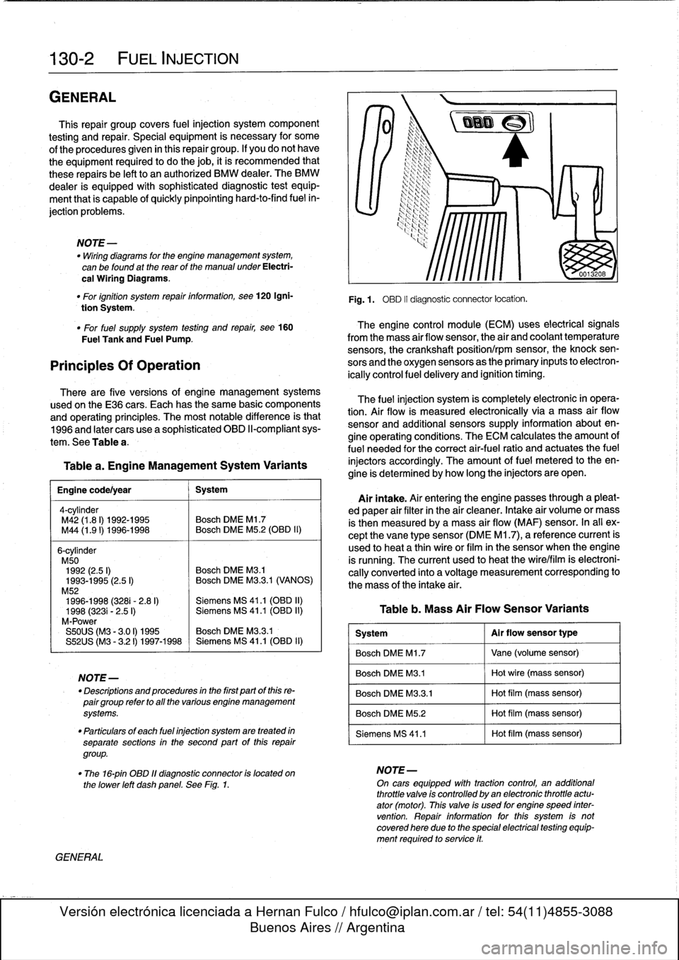
Table
a
.
Engine
Management
System
Variants
Engine
code/year
1
System
4-cy1inder
M42
(1
.8
I)
1992-1995
Bosch
DME
Ml
.7
M44
(1
.91)
1996-1998
~
Bosch
DME
M5
.2
(OBD
II)
6-cylinder
M50
1992
(2.5
I)
Bosch
DME
M3
.1
1993-1995
(2.5
I)
Bosch
DME
M3
.3.1
(VANOS)
M52
1996-1998
(3281-
2
.8
I)
Siemens
MS
41
.1
(OBD
II)
1998
(3231
-
2
.5
I)
Siemens
MS
41
.1
(OBD
II)
M-Power
S50US
(M3
-
3
.01)
1995
Bosch
DME
M3
.3
.1
S52US
(M3
-
3
.21)
1997-1998
Siemens
MS
41
.1
(0131)
11)
NOTE-
-
Descriptions
and
procedures
in
the
first
partof
this
re-
pairgroup
refer
to
all
the
various
engine
management
systems
.
"
Particulars
of
each
fuel
injection
system
are
treated
in
separate
sections
in
the
second
part
of
this
repair
group
.
GENERAL
Fig
.1
.
OBD
II
diagnostic
connector
locatíon
.
The
fuel
injection
system
is
completely
electronic
in
opera-
tion
.
Air
flow
is
measured
electronically
via
a
mass
air
flow
sensor
and
additional
sensors
supply
information
about
en-
gine
operating
conditions
.
The
ECM
calculates
the
amount
of
fuel
needed
for
the
correct
air-fuel
ratio
and
actuates
the
fuel
injectors
accordingly
.
The
amount
offuel
metered
to
theen-
gine
is
determined
by
how
long
the
injectors
are
open
.
Airintake
.
Air
entering
the
engine
passes
through
a
pleat-
ed
paper
air
filter
in
the
air
cleaner
.
Intake
air
volume
or
mass
is
then
measured
bya
mass
air
flow
(MAF)
sensor
.
In
al¡
ex-
cept
the
vane
type
sensor
(DME
M1
.7),
a
reference
current
is
used
to
heat
a
thin
wireor
film
in
the
sensor
when
the
engine
is
running
.
The
current
used
to
heat
the
wire/film
is
electroni-
cally
converted
into
a
voltage
measurement
corresponding
to
the
mass
of
the
intake
air
.
Table
b
.
Mass
Air
Flow
Sensor
Variants
System
Al
r
flow
sensor
type
Bosch
DME
M1
.7
Vane
(volume
sensor)
Bosch
DME
M3
.1
Hot
wire
(mass
sensor)
Bosch
DME
M3
.3
.1
Hot
film
(mass
sensor)
Bosch
DME
M5
.2
Hot
film
(mass
sensor)
Siemens
MS
41
.1
Hot
film
(mass
sensor)
"
The
16-pin
OBD
11
diagnostic
connector
is
located
on
NOTE-
the
lower
left
dashpanel
.
See
Fig
.
1
.
On
cars
equipped
wíth
tractioncontrol,
an
additional
throttle
valve
is
controlled
by
an
electronic
throttle
actu-
ator
(motor)
.
This
valve
is
used
for
engine
speed
inter
vention
.
Repair
information
forthis
system
is
notcovered
here
due
to
the
special
electrical
testing
equip-
ment
required
to
service
it
.
Page 154 of 759
130-
8
FUEL
INJECTION
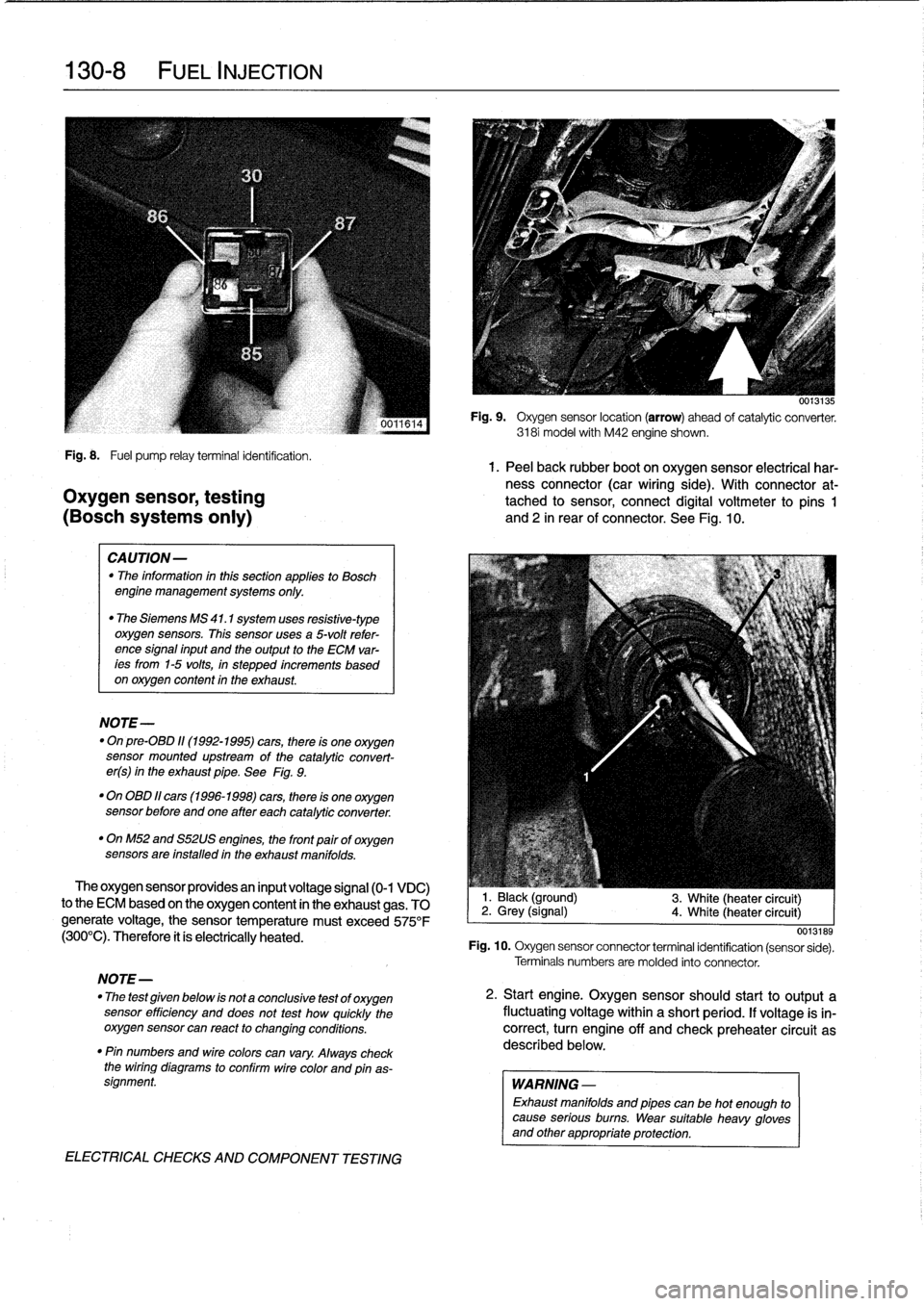
Fig
.
8
.
Fuel
pump
relayterminal
identification
.
1.
Peel
back
rubber
boot
on
oxygen
sensor
electrical
har-
ness
connector
(car
wiring
side)
.
With
connector
at-
Oxygen
sensor,
testing
tached
to
sensor,
connect
digital
voltmeter
to
pins
1
(BOSch
systems
only)
and
2
in
rear
of
connector
.
See
Fig
.
10
.
CAUTION-
"
The
information
inthis
sectionapplies
to
Bosch
engine
management
systems
only
.
"
The
Siemens
MS
41
.1
system
uses
resistive-type
oxygen
sensors
.
This
sensor
uses
a
5-volt
refer-
ence
signal
input
and
the
output
to
the
ECM
var-
ees
from
1-5
volts,
in
stepped
increments
based
on
oxygen
content
in
the
exhaust
.
NOTE-
"
On
pre-08D
11(1992-1995)
cars,
there
is
one
oxygen
sensor
mounted
upstream
of
the
catalytic
convert-
er(s)
in
the
exhaust
pipe
.
See
Fig
.
9
.
"
On
OBD
11
cars
(1996-1998)
cars,
there
is
one
oxygen
sensor
before
andone
after
each
catalytic
converter
.
"
OnM52
and
S52US
engines,
the
front
pairof
oxygen
sensors
are
installed
in
the
exhaust
manifolds
.
The
oxygen
sensor
providesan
input
voltage
signal
(0-1
VDC)
to
the
ECM
based
on
the
oxygen
content
in
the
exhaust
gas
.
TO
generate
voltage,
the
sensor
temperature
must
exceed
575°F
(300°C)
.
Therefore
it
ís
electrically
heated
.
NOTE-
"
The
test
given
below
is
not
a
conclusive
test
of
oxygen
sensor
efficiency
and
does
not
test
how
quickly
the
oxygensensor
can
react
to
changing
conditions
.
"
Pin
numbers
and
wirecolors
can
vary
.
Always
check
the
wiring
diagrams
to
conflrm
wire
color
and
pinas-
signment
.
ELECTRICAL
CHECKS
AND
COMPONENT
TESTING
0013135
Fig
.
9
.
Oxygen
sensor
location
(arrow)
ahead
of
catalytic
converter
.
3181
model
with
M42
engine
shown
.
1
.
Black
(ground)
2
.
Grey
(signal)
4
.
White
(heater
circuit)
3
.
White
(heater
circuit)
0013189
Fig
.
10
.
Oxygen
sensor
connector
terminal
identification
(sensor
sede)
.
Terminals
numbers
are
molded
into
connector
.
2
.
Start
engine
.
Oxygen
sensorshould
start
to
output
a
fluctuating
voltage
within
a
short
period
.
If
voltage
is
in-
correct,
turn
engine
off
and
check
preheater
circuit
as
described
below
.
WARNING
-
Exhaust
manifolds
and
pipes
can
be
hot
enough
to
cause
serious
burns
.
Wear
suitable
heavy
gloves
and
other
appropriate
protection
.
Page 161 of 759
u0
I
.[
Ia
Fig
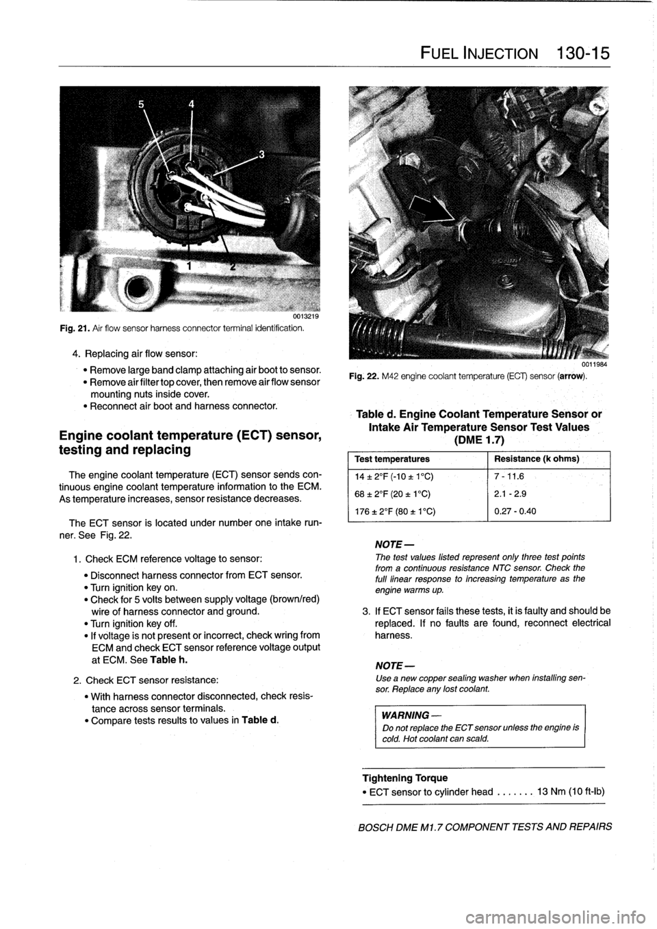
.
21
.
Air
flow
sensor
harness
connector
terminal
identification
.
4
.
Replacing
air
flow
sensor
:
"
Remove
large
band
clamp
attaching
air
boot
to
sensor
.
"
Remove
airfiltertop
cover,
then
remove
airflow
sensor
mounting
nuts
inside
cover
.
"
Reconnect
air
boot
and
harness
connector
.
Engine
coolant
temperature
(ECT)
sensor,
testing
and
replacing
The
engine
coolant
temperature
(ECT)
sensor
sends
con-
tinuous
engine
coolant
temperature
information
to
the
ECM
.
As
temperature
increases,
sensor
resistance
decreases
.
"
With
harness
connector
disconnected,
check
resis-
tance
across
sensor
terminals
.
"
Compare
tests
results
to
values
in
Table
d
.
FUEL
INJECTION
130-
1
5
0011984
Fig
.
22
.
M42
engine
coolant
temperature
(ECG
sensor
(arrow)
.
Table
d
.
Engine
Coolant
Temperature
Sensoror
Intake
Air
TemperatureSensor
Test
Values
(DME
1
.7)
Test
temperatures
Resistance
(k
ohms)
',
14±2°F(-10t1°C)
7-11
.6
68±2°F
(20
t
1
°C)
2
.1
-2
.9
176
±
2°F
(80
t
V
C)
0
.27-0
.40
The
ECT
sensor
is
located
under
number
one
intake
run-
'
ner
.
See
Fig
.
22
.
NOTE-
1
.
Check
ECM
referente
voltage
to
sensor
:
The
test
values
listed
represent
only
three
test
points
from
a
continuous
resistance
NTC
sensor
.
Check
the
"
Disconnect
harness
connectorfrom
ECT
sensor
.
full
linear
response
to
increasing
temperature
as
the
"
Turn
ignition
key
on
.
engine
warms
up
.
"
Check
for
5
volts
between
supply
voltage
(brown/red)
wire
of
harness
connector
and
ground
.
3
.
If
ECT
sensor
fails
these
tests,
it
is
faulty
and
should
be
"
Turn
ignition
key
off
.
replaced
.
If
no
faults
are
found,
reconnect
electrical
"
If
voltage
is
not
present
or
incorrect,
check
wring
from
harness
.
ECM
and
check
ECT
sensor
reference
voltage
output
at
ECM
.
See
Table
h
.
NOTE-
2
.
Check
ECT
sensor
resistance
:
Use
a
new
copper
sealing
washer
when
installing
sen-
sor
.
Reptace
any
lost
coolant
.
WARNING
-
Do
not
replace
the
ECT
sensor
unlessthe
engine
is
cold
.
Hot
coolant
can
scald
.
Tightening
Torque
"
ECT
sensor
to
cylinder
head
.....
..
13
Nm
(10
ft-Ib)
BOSCH
DME
M1
.7
COMPONENT
TESTS
AND
REPAIRS
Page 163 of 759
BOSCH
DME
MM
AND
M33
.1
COMPONENT
TESTS
AND
REPAIRS
Consult
Table
a
for
engine
application
information
for
the
Bosch
DME
3
.1
and
3
.3.1
systems
.
The
DME
3
.1
and
DME
3
.3
.1
systems
are
similar
in
opera-
tion,
with
knock
control
and
VANOS
operation
being
the
key
differences
.
DME
3
.1
engines
arenot
equipped
with
VANOS
or
knock
detectors,
while
the
DM
E3
.3
.1
system
is
.
CA
UTION-
Use
onty
a
digital
multimeter
when
testing
wiring
.
Use
of
an
analog
VOM
may
damage
the
engine
control
module
.
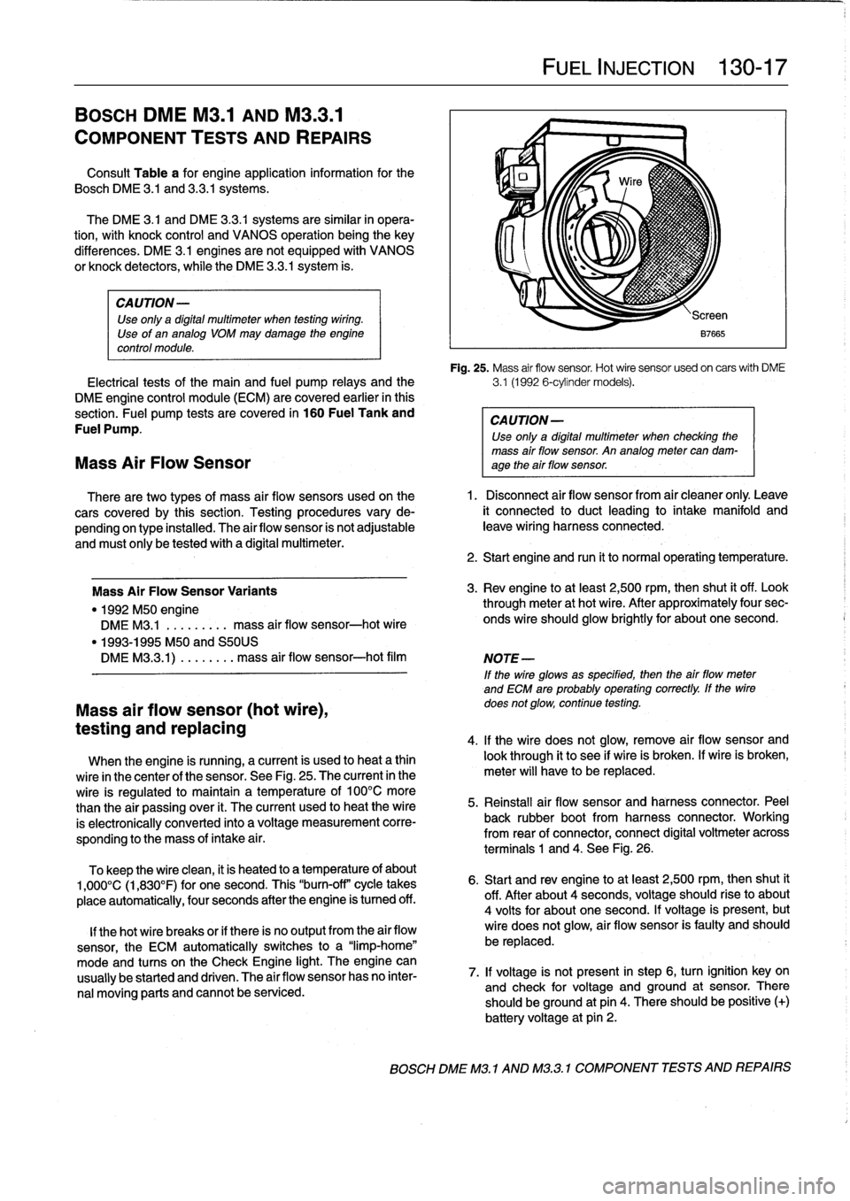
Fig
.
25
.
Mass
air
flow
sensor
.
Hot
wire
sensor
usedon
carswith
DME
Electrical
tests
of
the
main
and
fuel
pump
relays
and
the
3
.1
(1992
6-cylinder
models)
.
DME
engine
control
module
(ECM)
are
covered
earlier
in
this
section
.
Fuel
pump
tests
are
covered
in
160
Fuel
Tank
and
CAUTION-
Fuel
Pump
.
Use
only
a
digital
multimeter
when
checking
the
mass
air
flow
sensor
.
An
analog
meter
can
dam-
Mass
Air
Flow
Sensor
age
theair
flow
sensor
.
There
are
two
types
of
mass
air
flow
sensors
used
onthe
1
.
Disconnect
air
flow
sensor
from
air
cleaner
only
.
Leave
cars
covered
by
this
section
.
Testing
procedures
vary
de-
it
connected
to
duct
leading
to
intake
manifold
and
pending
on
type
installed
.
The
airflow
sensor
is
not
adjustable
leave
wiring
harness
connected
.
and
must
only
be
tested
with
a
digital
multimeter
.
Mass
Air
FlowSensor
Variants
"
1992
M50
engine
DME
M3
.1
.
.
.
.
...
..
mass
air
flow
sensor-hot
wire
"
1993-1995
M50
and
S50US
DMEM33
.1)
.
...
...
.
mass
air
flow
sensor-hot
film
Mass
air
flow
sensor
(hot
wire),
testing
and
replacing
When
the
engine
is
running,
a
current
is
used
to
heat
a
thin
wire
in
the
center
of
the
sensor
.
See
Fig
.
25
.
The
current
in
the
wire
is
regulated
to
maintain
a
temperature
of
100°C
more
than
the
air
passing
over
it
.
The
current
used
to
heat
the
wire
is
electronically
conneced
into
a
voltage
measurement
corre-
sponding
to
the
mass
of
intake
a¡
r
.
To
keep
the
wire
clean,
it
is
heated
to
a
temperature
of
about
1,000°C
(1,830°F)
for
one
second
.
This
"burn-off"
cycle
takes
place
automatically,
four
seconds
after
the
engine
is
tumed
off
.
lf
thehot
wire
breaks
or
if
there
is
no
output
from
the
air
flow
sensor,
the
ECM
automatically
switches
to
a
"limp-home"
mode
and
tucos
on
the
Check
Engine
light
.
The
engine
can
usually
be
started
and
driven
.
The
air
flow
sensor
has
no
inter-
nal
moving
parts
and
cannot
be
serviced
.
FUEL
INJECTION
130-
1
7
2
.
Start
engine
and
run
it
to
normal
operating
temperature
.
3
.
Rev
engine
toat
least
2,500
rpm,then
shut
it
off
.
Look
through
meter
at
hot
wire
.
After
approximately
four
sec-
onds
wire
should
glow
brightly
for
about
one
second
.
NOTE
-
If
the
wire
glowsas
specified,
then
the
airflow
meter
and
ECM
are
probably
operating
correctly
.
lf
the
wire
does
not
glow,
continue
testing
.
4
.
lf
the
wire
does
not
glow,
remove
air
flow
sensor
and
look
through
it
to
see
if
wire
is
broken
.
lf
wire
is
broken,
meter
will
have
to
be
replaced
.
5
.
Reinstall
air
flow
sensor
and
harness
connector
.
Peel
back
rubber
bootfrom
harness
connector
.
Working
from
rear
of
connector,
connect
digital
voltmeter
across
terminals
1
and
4
.
See
Fig
.
26
.
6
.
Start
and
rev
engine
toat
least
2,500
rpm,thenshut
it
off
.
After
about
4
seconds,
voltage
should
riseto
about
4
volts
for
about
one
second
.
lf
voltage
is
present,
but
wire
does
not
glow,
air
flow
sensor
is
faulty
and
should
be
replaced
.
7
.
lf
voltage
is
not
present
in
step
6,
turn
ignition
key
on
and
check
for
voltage
and
ground
at
sensor
.
There
should
beground
at
pin
4
.
There
should
be
positive
(+)
battery
voltage
at
pin
2
.
BOSCH
DME
M3
.1
AND
M32
.1
COMPONENT
TESTS
AND
REPAIRS
Page 164 of 759
130-18
FUEL
INJECTION
The
engine
coolant
temperature
(ECT)
sensor
sends
con-
tinuous
engine
coolant
temperature
information
to
the
ECM
.
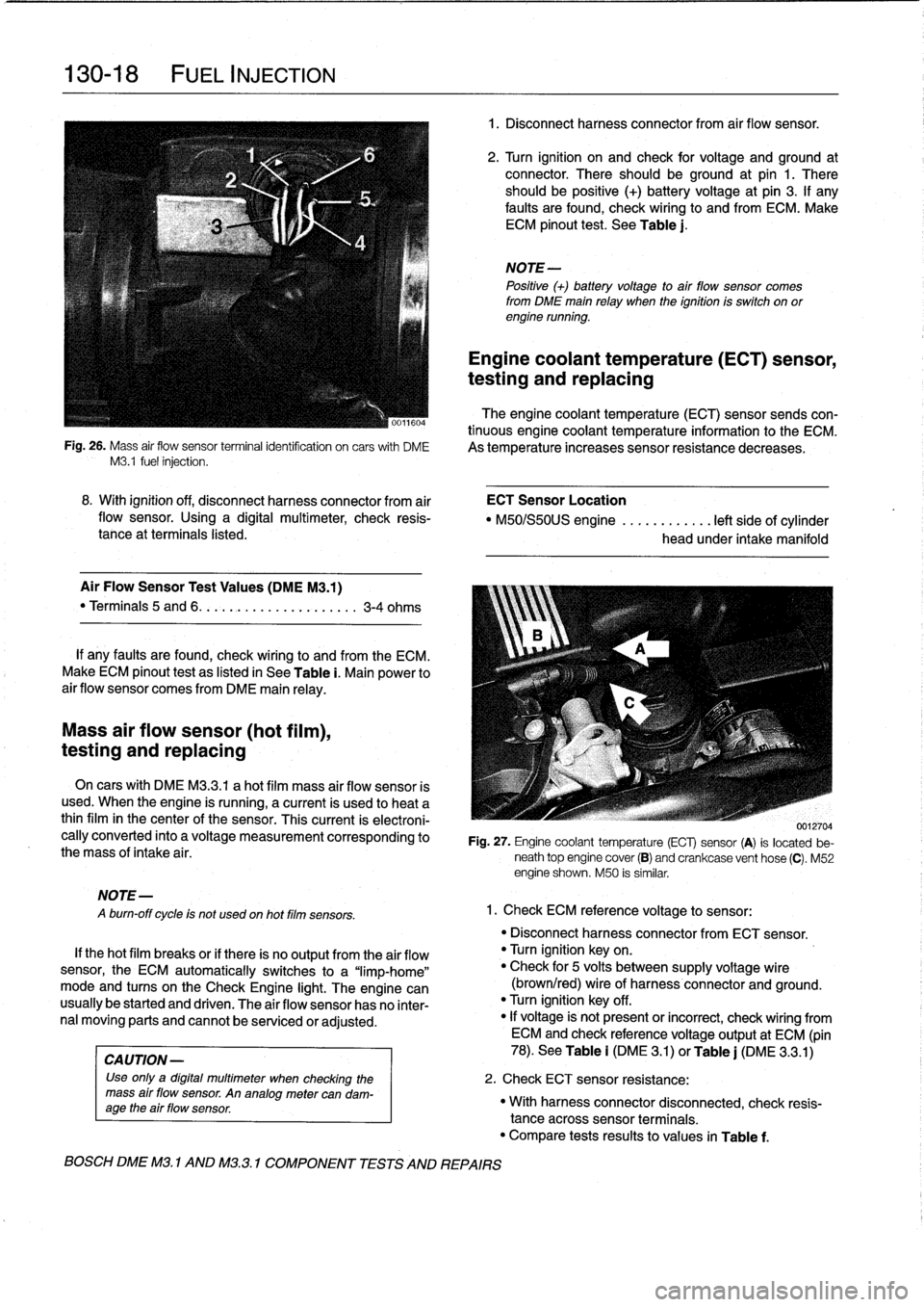
Fig
.
26
.
Mass
air
flow
sensor
terminalidentifcation
on
carswith
DME
As
temperature
increases
sensor
resistance
decreases
.
M3
.1
fuel
injection
.
Mass
air
flow
sensor
(hot
film),
testing
and
replacing
MOTE-
A
burn-off
cycle
is
not
used
on
hot
film
sensors
.
8
.
With
ignition
off,
disconnect
harness
connector
from
air
ECT
Sensor
Location
flow
sensor
.
Using
a
digital
multimeter,
check
resis-
"
M50/S50US
engine
............
left
side
of
cylinder
tance
at
terminals
listed
.
head
under
intake
manifold
Air
Flow
Sensor
Test
Values
(DMEM3
.1)
"
Terminals
5
and
6
.
.
.
.........
..
.
..
....
3-4
ohms
If
any
faults
are
found,
check
wiring
lo
and
from
the
ECM
.
Make
ECM
pinout
test
as
listed
in
See
Table
i
.
Main
power
to
air
flow
sensor
comes
from
DME
main
relay
.
On
cars
with
DME
M3
.3
.1
a
hot
film
mass
air
flow
sensor
is
used
.
When
the
engine
is
running,
a
current
is
used
lo
heat
a
thinfilm
in
the
center
of
the
sensor
.
This
current
is
electroni-
cally
converted
into
a
voltage
measurement
corresponding
to
the
mass
of
intake
air
.
If
thehot
film
breaks
or
if
there
is
no
output
from
the
air
flow
sensor,
the
ECM
automatically
switches
to
a
"limp-home"
mode
and
tucos
on
the
Check
Engine
light
.
The
engine
can
usually
be
started
and
driven
.
The
air
flow
sensor
has
no
inter-
nal
moving
parts
and
cannot
be
senricedor
adjusted
.
CA
UTION-
Use
only
a
digital
multimeter
when
checking
the
mass
air
flow
sensor
.
An
analogmetercan
dam-
age
the
air
flow
sensor
.
BOSCH
DME
M3
.
1
AND
M32
.1
COMPONENT
TESTS
AND
REPAIRS
1
.
Disconnect
harnessconnector
from
air
flow
sensor
.
2
.
Turn
ignition
on
and
check
for
voltage
and
ground
at
connector
.
There
should
beground
at
pin
1
.
There
should
be
positive
(+)
battery
voltage
at
pin
3
.
If
any
faults
are
found,
check
wiring
to
and
from
ECM
.
Make
ECM
pinout
test
.
See
Table
j
.
NOTE-
Positive
(+)
battery
voltage
to
air
flow
sensor
comes
from
DME
main
relay
when
the
ignition
is
switch
on
orengine
running
.
Engine
coolant
temperature
(ECT)
sensor,
testing
and
replacing
0012704
Fig
.
27
.
Engine
coolant
temperature
(ECT)
sensor
(A)
is
located
be-
neath
top
engine
cover
(B)
and
crankcase
vent
hose
(C)
.
M52
engine
shown
.
M50
is
similar
.
1
.
Check
ECM
reference
voltage
to
sensor
:
"
Disconnect
harnessconnector
from
ECT
sensor
.
"
Turn
ignition
keyon
.
"
Check
for
5
volts
between
supply
voltage
wire
(brown/red)
wire
of
harness
connector
and
ground
.
"
Turn
ignition
key
off
.
"
If
voltage
is'
not
present
or
incorrect,
check
wiring
from
ECM
and
check
referencevoltage
output
at
ECM
(pin
78)
.
See
Table
i
(DM
E
3
.1)
or
Table
j
(DME
3
.3
.1)
2
.
Check
ECT
sensor
resistance
:
"
With
harnessconnector
disconnected,
check
resis-
tance
acrosssensor
terminals
.
"
Compare
tests
results
to
values
in
Table
f
.
Page 165 of 759
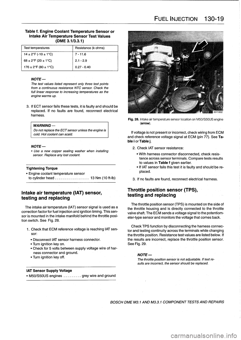
Table
f
.
Engine
Coolant
TemperatureSensor
or
Intake
Air
TemperatureSensor
Test
Values
(DME
3
.113
.3
.1)
Test
temperatures
Resistance
(k
ohms)
14±
2°F
(-10
±
1'C)
7-11
.6
68±
2°F
(20
±
1'C)
2
.1
-2
.9
17612°F
(80
t
V
C)
0
.27-0
.40
NOTE
The
test
values
listed
represent
only
three
test
points
from
a
continuous
resistance
NTC
sensor
.
Check
the
full
linear
response
to
increasing
temperatures
as
the
engine
warms
up
.
3
.
If
ECT
sensor
fails
these
tests,
it
is
faulty
and
should
be
replaced
.
If
no
faults
are
found,
reconnect
electrical
harness
.
WARNING
-
Do
not
replace
the
ECT
sensor
unless
the
engine
is
cold
.
Hot
coolant
can
scald
.
NOTE-
Use
"
a
new
copper
sealing
washer
when
installing
sensor
.
Replace
any
lost
coolant
.
Tightening
Torque
"
Engine
coolant
temperature
sensor
to
cylinder
head
.........
..
.
..
...
13
Nm
(10
ft-lb)
Intake
air
temperature
(IAT)
sensor,
testing
and
replacing
The
intake
air
temperature
(IAT)
sensor
signal
is
usedasa
correction
factor
for
fuel
injection
and
ignition
timing
.
Thissen-
sor
is
mounted
in
the
intake
manifold
behind
the
throttle
posi-
tion
switch
.
See
Fig
.
28
.
Check
TPS
function
by
disconnecting
theharnessconnec-
1
.
Check
that
ECM
reference
voltage
is
reaching
IAT
sen-
tor
and
testing
continuity
across
the
terminalswhile
changing
sor
:
the
throttle
position
.
Resistance
test
values
are
listed
below
.
If
"
Disconnect
IAT
sensor
harness
connector
.
the
resuits
are
incorrect,
replace
the
throttle
position
sensor
.
"
Turn
ignition
keyon
.
See
Fig
.
29
.
"
Check
for
5
volts
between
supply
voltage
wire
of
har-
ness
connector
and
ground
.
NOTE-
"
Turn
ignition
key
off
.
The
throttle
position
sensor
is
not
adjustable
.
If
test
re-
sults
are
incorrect,
the
sensor
should
be
replaced
.
IAT
Sensor
Supply
Voltage
"
M50/S50US
engines
.
........
grey
wire
and
ground
FUEL
INJECTION
130-19
Fig
.
28
.
Intake
air
temperature
sensor
location
on
M50/S50US
engine
(arrow)
.
If
voltage
is
not
present
or
incorrect,
check
wiring
from
ECM
and
check
reference
voltage
signal
at
ECM
(pin
77)
.
See
Ta-
ble
i
or
Table
j
.
2
.
Check
IAT
sensor
resistance
:
"
With
harness
connector
disconnected,
check
resis-
tance
acrosssensor
terminals
.
Compare
tests
resuits
to
values
in
Table
f
given
earlier
.
"
If
IAT
sensor
fafs
thistest
it
is
faulty
and
should
be
re-
placed
.
3
.
If
no
faults
are
found,
reconnect
electrical
harness
.
Throttle
position
sensor
(TPS),
testing
and
replacing
The
throttle
position
sensor
(TPS)
is
mounted
on
the
side
of
the
throttle
housing
and
is
directly
connected
to
the
throttle
valve
shaft
.
The
ECM
sends
a
voltage
signal
to
the
potentiom-
eter-type
sensor
and
monitors
the
voltage
that
comes
back
.
BOSCH
DME
M3
.
1
AND
M32
.1
COMPONENT
TESTS
AND
REPAIRS
Page 176 of 759
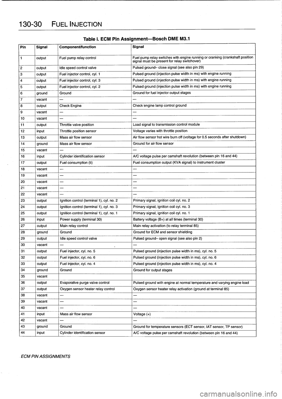
130-
3
0
FUEL
INJECTION
Pin
Signal
Component/function
Signal
ECM
PIN
ASSIGNMENTS
Table
1.
ECM
Pin
Assignment-Bosch
DME
M3
.1
1
output
Fuel
pump
relay
control
Fuel
pump
relay
switches
with
engine
runningor
cranking
(crankshaft
position
Signal
mustbe
present
for
relay
switchover)
2
1
output
1
Idle
speed
control
valve
1
Pulsad
ground-
close
signal
(seealsopin29)
3
output
Fuel
injectorcontrol,
cyl
.
1
Pulsedground
(injection
pulsewidth
in
ms)
with
engine
running
4
output
Fuel
injectorcontrol,
cyl
.
3
Pulsedground
(injection
pulsewidth
in
ms)
with
engine
running
5
output
Fuel
injector
control,
cyl
.
2
Pulsedground
(injection
pulse
width
in
ms)
with
enginerunning
6
ground
Ground
Ground
for
fuel
injector
output
stages
7
vacant
-
-
8
output
Check
Engine
Check
éngine
lamp
control
ground
9
vacant
-
-
10
vacant
-
-
11
output
Throttle
valve
position
Load
signal
to
transmission
control
module
12
input
Throttle
position
sensor
Voltage
varies
with
throttle
position
13
output
Mass
air
flow
sensor
Air
flow
sensor
hotwire
burn
off
(voltage
for
0
.5
seconds
after
shutdown)
14
ground
Mass
air
flow
sensor
Ground
for
air
flow
sensor
15
vacant
-
-
16
input
Cylinder
identification
sensor
A/C
voltage
pulse
per
camshaft
revolution
(between
pin
16
and
44)
17
output
Fuel
consumption
(ti)
Fuel
consumption
output
(KVA
Signal)
to
instrument
cluster
18
vacant
-
-
19
vacant
-
-
20
vacant
-
-
21vacant
-
-
22
vacant
-
-
23
output
Ignition
control
(terminal
1),
cyl
.
no
.
2
Primary
Signal,
ignition
coil
cyl
.
no
.
2
24
output
Ignition
control
(terminal
1),
cyl
.
n
o
.
3
Primary
signal,
ignition
coil
cyl
.
no
.
3
25
output
Ignition
control
(terminal
1),
cyl
.
n
o
.
1
Primary
signal,
ignitioh
coil
cyl
.
no
.
1
26
input
Power
supply
(terminal
30)
Battery
voltage
(B+)
at
al¡
times
(terminal
30)
27
output
Main
relay
control
Main
relay
activation
(to
relay
terminal
85)
28
ground
Ground
Ground
for
ECM
and
sensor
shielding
29
output
Idle
speed
control
valve
Pulsed
ground-
open
signal
(see
also
pin
2)
30
vacant
-
-
31
output
Fuel
injector,cyl
.
no
.
5
Pulsedground
(injection
pulsewidth
in
ms),
cyl
.
no
.
5
32
output
Fuel
injector,cyl
.
no
.
6
Pulsedground
(injection
pulse
width
in
ms),
cyl
.
no
.
6
33
output
Fuel
injector,cyl
.
no
.
4
Pulsedground
(injection
pulsewidth
in
ms),
cyl
.
no
.
4
34
ground
Ground
Ground
for
output
stages
35
vacant
36
output
Evaporative
purgevalve
control
Pulsed
ground
with
engine
at
normal
temperature
and
varying
engine
load
37
output
Oxygen
sensor
heater
relay
control
Oxygen
sensor
heater
relayactivation
(ground
at
terminal
85)
38
vacant
-
-
39
vacant
-
-
40
vacant
-
41
input
Mass
air
flow
sensor
Voltage
(+)
42
vacant
-
-
43
ground
Ground
Ground
for
temperatura
sensors
(ECT
sensor,
IAT
sensor,
TP
sensor)
44
input
Cylinder
identification
sensor
A/C
voltagepulseper
camshaft
revolution
(between
pin
16
and
44)