600 BMW 325i 1992 E36 Workshop Manual
[x] Cancel search | Manufacturer: BMW, Model Year: 1992, Model line: 325i, Model: BMW 325i 1992 E36Pages: 759
Page 3 of 759
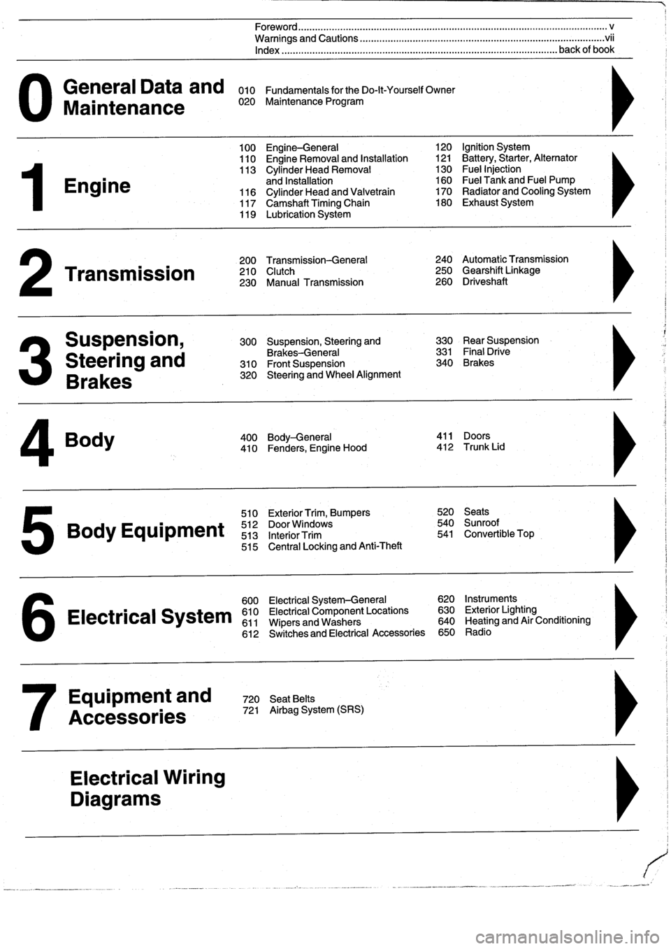
General
Data
and
010
FundamentalsfortheDo-lt-YourselfOwner
Maintenance
020
Maintenance
Program
Engine
Transmission
Suspension,
Steering
and
Brakes
4
Body
100
Engine-General
110
Engine
Removal
and
Installation
113
Cylinder
Head
Removal
and
Installation
116
Cylinder
Head
and
Valvetrain
117
Camshaft
Timing
Chain
119
Lubrication
System
200
Transmission-General
210
Clutch
230
Manual
Transmission
510
Exterior
Trim,
Bumpers
520
Seats
Bo
y
Equipment
512
DoorWTdws
540
nr
t
513
InteriorTrim
541
Convertible
Top
515
Central
Locking
and
Anti-Theft
600
Electrical
System-General
620
Instruments
Electrical
S
stem
610
Electrical
Component
Locations
630
Exterior
Lighting
611
Wipers
and
Washers
640
Heating
and
Air
Conditioning
6
612
Switches
and
Electrical
Accessories
650
Radio
Equipment
and
720
SeatBelts
Accessories
721
Airbag
System
(SRS)
Electrical
Wiring
Diagrams
Foreword
.
...
.
.
.
..................
.
.
.
.....
.
............
.
...
.
.
.
.
.
................
.
.
.
.....
.
......
.
................
.
.
.
.....
v
Warnings
and
Cautions
.....
.
...
.
.
.
.
.
..........
.
...
.
.
.
.
.
......
.
.........
.
.
.
...
.
.
.
......
.
.
.
.
.
............
.
.
.
.
.
.
.vii
Index
..............
.
.
.
.....
.
............
.
...
.
.
.
.
.
........
.
...
.
.
.
.
.
.......
.
......
.
...
.
.
.
.
.
.
.
........
.
.
.
..
back
of
book
300
Suspension,
Steering
and
330
RearSuspension
Brakes-General
331
Final
Drive
310
Front
Suspension
340
Brakes
320
Steering
and
Wheel
Alignment
400
Body-General
411
Doors
410
Fenders,
Engine
Hood
412
Trunk
Lid
120
Ignition
System
121
Battery,Starter,
Alternator
130
Fue¡
Injection
160
Fuel
Tank
and
Fuel
Pump
170
Radiator
and
Cooling
System180
Exhaust
System
240
Automatic
Transmission
250
Gearshift
Linkage
260
Driveshaft
Page 14 of 759
010-
6
FUNDAMENTALS
FOR
THE
DO-ITYOURSELF
OWNER
In
places
where
a
shaft
mustpass
through
a
housing,
flexible
lip
seals
areused
to
keep
the
lubricating
oil
or
grease
from
leak-
ingout
past
the
rotating
shaft
.
Seals
should
never
be
reused
once
they
have
been
removed
.
When
removing
a
seal,
be
care-
ful
not
lo
scratch
or
otherwise
damage
the
metal
surfaces
.
Even
minor
damage
to
sealing
surfaces
can
cause
sea¡
damage
and
leakage
.
The
key
to
sea¡
installation
is
to
get
the
sea¡
in
straight
without
damaging
¡t
.
Use
a
sea¡
driver
that
is
the
same
diameter
as
the
seal
housing
to
gently
and
evenly
insta¡I
into
place
.
If
a
proper
size
seal
driver
is
not
available,
a
socket
of
the
right
size
will
do
.
When
installing
a
seal,
¡t
a
good
idea
to
coat
the
sea¡
with
o¡I
to
aid
installation
.
Some
seals
are
directional
and
special
instal-
lation
instructions
apply
.
Make
sure
¡t
is
installed
with
the
lip
fac-
ing
the
correct
way
.
Normally
the
lip
faces
the
inside
.
Note
the
installation
direction
of
the
old
sea¡before
removing
¡t
.
Electrical
Testing
Many
electrical
problems
canbe
understood
and
solved
with
only
a
little
fundamental
knowledge
of
how
electrical
circuits
Insulate
the
finished
connection
.
Electronics
stores
can
sup-
function
.
ply
heat-shrinkable
insulating
tubing
that
can
be
placed
onto
the
wire
before
connectiog,
slid
over
the
finished
joint,
and
Electric
current
only
flows
in
a
complete
circuit
.
To
operate,
shrunk
to
a
tight
fit
with
a
heat
gun
orhair
dryer
.
The
nextbest
every
electrical
device
in
thecar
requires
a
complete
circuit
in-
alternative
is
electrical
tape
.
Make
sure
the
wire
is
clean
and
cluding
a
voltage
source
and
a
pathto
ground
.
The
positive
(+)
free
ofsolder
flux
or
other
contamination
.
Wrap
the
joint
tightly
side
of
the
battery
is
the
original
voltagesource,
and
ground
is
to
sea¡
out
moisture
.
See
600
Electrical-General
for
more
in-
any
retum
path
to
the
negative
()
-
side
ofth
e
battery°
whether
li
formation
.
through
the
wiring
harness
or
thecar
body
.
Except
for
portions
of
the
charging
system,
al¡
electrical
current
in
the
car
is
direct
current
(DC)
and
flows
from
positive
(+)
to
negative
(-)
.
BVYING
PART$
Switches
are
used
to
turn
components
on
or
off
by
complet-
ing
or
interrupting
#he
circuit
.
A
switch
is
"open"
when
the
circuit
Many
of
the
maíntenance
and
repair
tasks
in
this
manual
cal¡
is
ínterrupted,
and
"closed"
when
the
circuit
is
completed
.
Fig
.
5
for
the
installation
of
new
parte,
or
the
use
of
new
gaskets
and
shows
a
basic
circuit
schematic
.
See600
Electrical
System-
other
materials
when
reinstalling
parts
.
Most
often,
the
parts
General
for
electrical
troubleshooting
.
that
will
be
needed
should
be
on
hand
beforebeginningthe
job
.
Read
the
introductory
text
and
the
complete
procedure
to
de-
termine
which
parts
will
be
needed
.
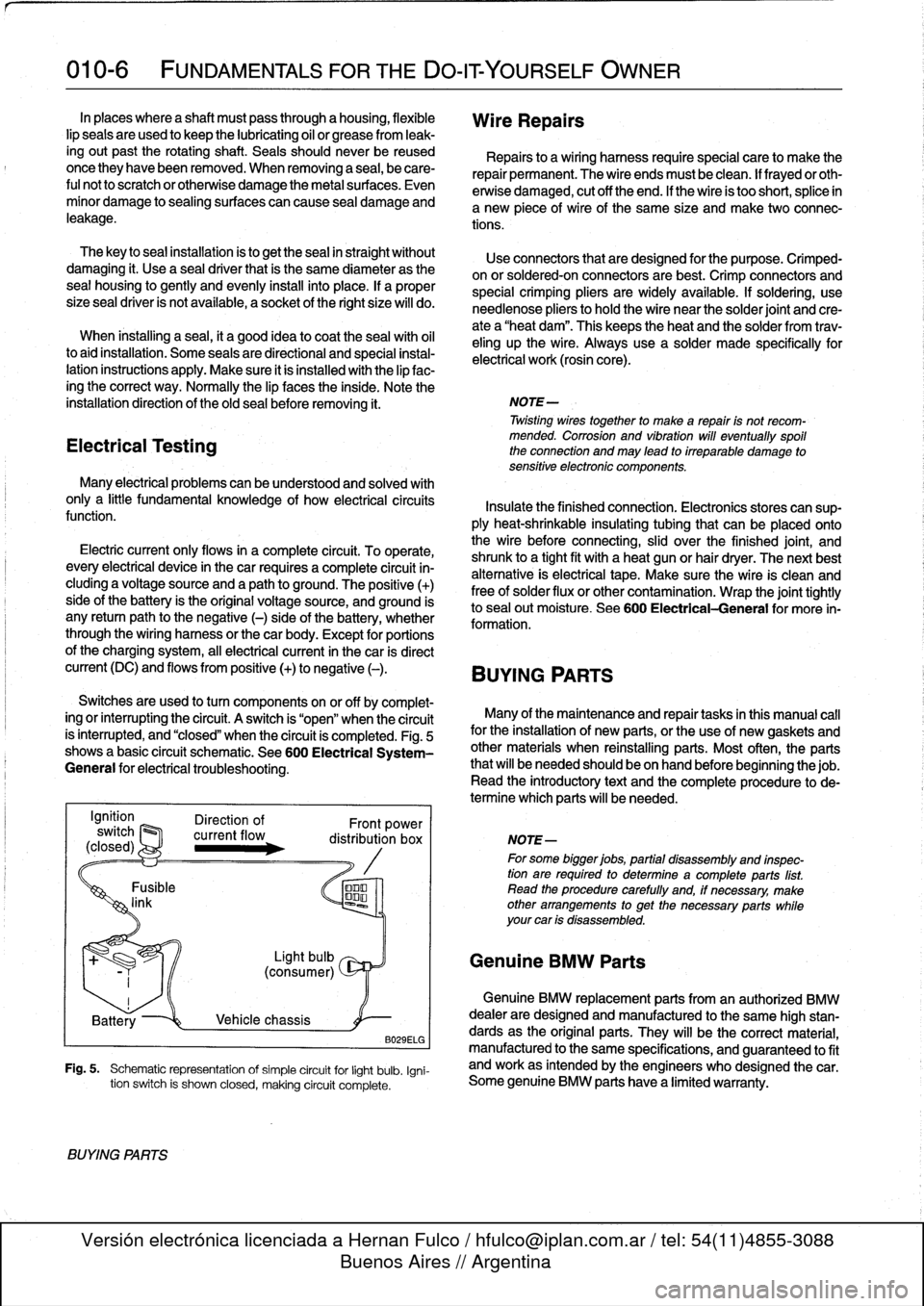
B029ELG
Fig
.
5
.
Schematic
representation
of
simple
circuit
for
light
bulb
.
Igni-
tion
switch
is
shown
closed,
making
circuit
complete
.
BVYING
PARTS
Wire
Repairs
Repairs
to
a
wiring
harness
requirespecial
care
to
make
the
repair
permanent
.
The
wire
endsmust
be
clean
.
lf
frayedor
oth-
erwise
damaged,
cut
off
the
end
.
If
the
wire
is
too
short,
splice
in
a
new
piece
of
wire
of
the
same
size
and
make
two
connec-
tions
.
Use
connectors
that
are
designed
for
the
purpose
.
Crimped-
on
or
soldered-onconnectors
are
best
.
Crimp
connectors
and
special
crimping
pliers
are
widely
available
.
If
soldering,
use
needlenose
pliers
tohold
the
wire
near
the
solder
joint
and
cre-
ate
a
"heat
dam"
.
This
keeps
the
heat
and
the
solder
from
trav-
eling
up
the
wire
.
Always
use
a
solder
made
specifically
for
electrical
work
(rosin
core)
.
NOTE-
Twisting
wirestogether
to
make
a
repair
is
not
recom-
mended
.
Corrosion
and
vibration
will
eventually
spoil
the
connection
and
may
lead
to
irreparable
damage
to
sensitive
electronic
componente
.
NOTE-
For
some
bigger
jobs,
partial
disassembly
and
inspec-
tion
are
required
to
determine
acomplete
parts
list
.
Read
the
procedure
carefully
and,
if
necessary,
make
other
arrangements
to
get
the
necessary
parts
while
your
car
is
disassembled
.
Genuine
BMW
Parts
Genuine
BMW
replacement
parts
from
an
authorized
BMW
dealer
are
designed
and
manufactured
lo
the
same
high
stan-
dards
as
the
original
parts
.
They
will
be
the
correct
material,
manufactured
to
the
same
specifications,
and
guaranteed
lo
fit
and
work
as
intended
by
the
engineers
who
designed
thecar
.
Some
genuine
BMW
parts
have
a
limited
warranty
.
Page 43 of 759
GENERAL
.
.....
.
.
.
.
.
.
.
...
.
.
.
.
.
.
.
.
.
...
100-1
Cylinder
Block
and
Crankshaft
.
.
.
.
.
.
.
.
.
...
100-1
Connecting
Rods
and
Pistons
.
.
.
.
.
.
.
.
.
.
.
.
.
100-1
Cylinder
Head
and
Valvetrain
.
.
.
.
.
.
.
.
.
.
.
.
.
100-2
VANOS
(Variable
Valve
Timing)
.
.
.
.
.
.
.
.
...
100-2
DISA
(Dual
Resonance
Intake
System)
.
.
.
.
.
100-3
Engine
Management
System
.
.
.
.
.
.
.
.
.
.
.
.
.
100-3
Ignition
......
.
.
.
.........
.
.
.
.
.
.
.
.
.
.
.
.
100-5
Fuel
Delivery
..
.
.
.
.....
.
...
.
.
.
.
.
.
.
.
.
.
.
.
100-5
Cooling
System
.
...........
.
.
.
.
.
.....
.
.
100-5
Lubrication
System
.........
.
.
.
.
.
.
.
.
.
.
.
.
100-5
MECHANICALTROUBLESHOOTING
.
.
.
.
100-5
Warnings
and
Cautions
..
.
...
.
.
.
.
.
.
.
.
.
.
.
.
100-5
Cylinder
compression,
checking
.
.
.
.
.
.
.
.
.
.
.
100-6
EngineMechanical
Troubleshooting
Table
.
.
.
100-7
DRIVEABILITY
TROUBLESHOOTING
...
100-8
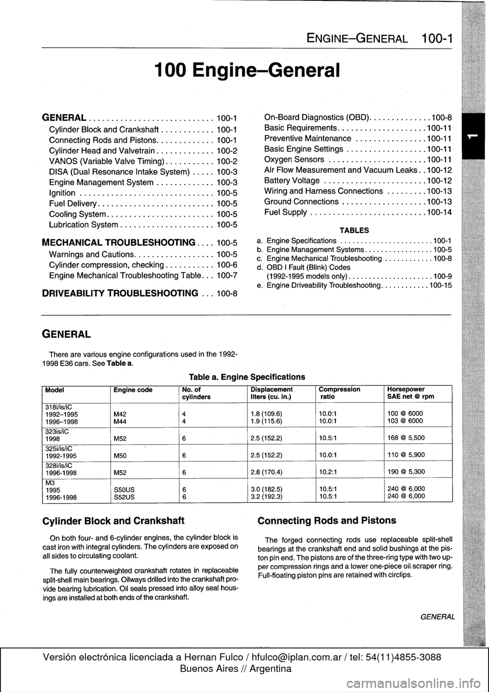
GENERAL
There
are
various
engíne
configurations
used
in
the
1992-
1998
E36
cars
.
See
Table
a
.
On
both
four-
and
6-cylinder
engines,
the
cylinder
block
is
cast
¡ron
with
integral
cyiinders
.
The
cyiinders
are
exposed
on
all
sides
to
circulating
coolant
.
The
fully
counterweighted
crankshaft
rotates
in
replaceable
split-shell
main
bearings
.
Oiiways
drilled
into
the
crankshaft
pro-
vide
bearing
lubrication
.
O¡I
seals
pressed
into
alloy
sea¡
hous-
ings
are
installedat
both
ends
of
the
crankshaft
.
100
Engine-General
Tablea
.
Engine
Specifications
ENGINE-GENERAL
100-1
On-Board
Diagnostics
(OBD)
...
.
.
.
.
.
.
.
.
.
.
.
100-8
Basic
Requirements
....
.
.
.
...
.
.
.
.
.
....
.100-11
Preventive
Maintenance
......
.
.
.
.
.
.....
100-11
Basic
Engine
Settings
..
.
.....
.
.
.
.
.
.....
100-11
Oxygen
Sensors
.
.
.
...
.
.
.
...
.
.
.
.
.
....
.100-11
Air
Flow
Measurement
and
Vacuum
Leaks
.
.100-12
Battery
Voltage
.
.
...........
.
.
.
.
.
.....
100-12
Wiring
and
Harness
Connections
.
.
.
.
.....
100-13
Ground
Connections
...
.
.....
.
.
.
.
.
.....
100-13
Fue¡
Supply
....
.
...........
.
.
..
.....
.100-14
TABLES
a
.
Engine
Specifications
...
...
...........
.
..
..
.100-1
b
.
Engine
Management
Systems
..
..
...........
..
100-5
c
.
Engine
Mechanical
Troubleshooting
..........
.
.
100-8
d
.
OBD
1
Fault
(Blink)
Codes
(1992-1995
models
only)
.
...
..
..
..........
..
.100-9
e
.
Engine
Driveability
Troubleshooting
...........
.100-15
Model
Engine
code
No
.
of
Dispiacement
Compression
Horsepower
cyiinders
liters
(cu
.
in
.)
ratio
SAE
net
@
rpm
318i/is/¡C
1992-1995
M42
4
1
.8
(109
.6)
10
.0
:1
100
@
6000
1996-1998
M44
4
1
.9
(115
.6)
~
10
.0
:1
103
@
6000
323ís/iC
1998
M52
6
2
.5
(152
.2)
10
.5
:1
168
@
5,500
325i/is/iC
1992-1995
M50
6
2
.5
(152
.2)
10
.0
:1
110
@
5,900
328i/is/iC
1996-1998
M52
6
2
.8
(170
.4)
10
.2
:1
190
@
5,300
M3
1995
S50US
6
3
.0
(182
.5)
10
.5:1
240
@
6,000
1996-1998
S52US
6
3
.2
(192
.3)
10
.5:1
240
@
6,000
Cylinder
Block
and
Crankshaft
Connecting
Rods
and
Pistons
The
forged
connecting
rods
use
replaceable
split-shell
bearings
at
the
crankshaft
endand
solid
bushings
at
the
pis-
ton
pin
end
.
The
pistonsare
of
the
three-ring
typewith
two
up-
per
compression
rings
and
a
lowerone-piece
o¡i
scraper
ring
.
Fui¡-floating
piston
pins
are
retained
with
circlips
.
GENERAL
Page 55 of 759
If
a
battery
cableconnection
hasno
visible
faults,
but
is
still
suspect,
measure
the
voltage
drop
across
the
connection
.
A
large
drop
indicates
excessive
resistance,
meaning
the
con-
nection
is
corroded,
dirty,
or
damaged
.
Clean
or
repair
the
connection
and
retest
.
NOTE-
For
instructions
on
conducting
a
voltage
drop
test,
and
other
general
electrical
troubleshooting
information,
see600
Electrical
System-General
.
Wiring
and
Harness
Connections
The
electronic
fuel
injection
and
ignition
systems
operate
at
low
voltage
and
current
values,
making
them
sensitive
to
small
increases
in
resistance
.
The
electrical
system
is
routine-
ly
subjected
to
corrosion,
vibration
and
wear,
so
faults
or
cor-
rosion
in
the
wiring
harness
and
connectors
are
common
causes
of
driveability
problems
.
Visually
inspect
all
wiring,
connectors,
switches
and
fuses
in
the
system
.
Loose
or
damaged
connectors
can
cause
inter-
mittent
problems,
especially
the
smallterminals
in
the
ECM
connectors
.
Disconnect
the
wiring
harness
connectors
to
check
for
corrosion
;
and
use
electrical
cleaning
spray
to
re-
move
contaminants
.
Often,
simply
disconnecting
and
recon-
necting
a
dirty
connector
several
times
will
clean
the
terminals
and
help
to
reestablish
good
electrical
contact
.
If
a
wiring
harnessconnectorhasno
visible
faults,
but
is
still
suspect,
measure
the
voltage
drop
across
the
connector
.
A
large
drop
indicates
excessive
resistance,
meaning
the
con-
nector
is
corroded,
dirty
or
damaged
.
Clean
or
repair
the
con-
nector
and
retest
.
Ground
Connections
For
any
electrical
circuit
to
work,
it
must
make
acomplete
path,
beginning
at
the
positive
(+)
battery
terminal
and
ending
at
the
negative
(-)
terminal
.
The
negative
(-)
battery
cable
is
attached
to
the
car's
chassis
.
Therefore,
any
wireor
metal
part
attached
to
the
chassis
provides
a
good
ground
path
back
to
the
negative
(-)
battery
terminal
.
Poorground
connections
are
amajor
source
of
driveabílity
problems
.
If
any
of
themainground
connections
for
the
igni-
tion
system
or
the
fuelinjection
system
are
faulty,
the
in-
creased
resistance
in
that
circuit
will
cause
problems
.
Visually
inspect
al¡
ground
wires
and
connections
for
breaks,
looseness
or
corrosion
.
Be
careful
because
wires
sometimes
break
internally
or
in
areas
not
easily
visible
.
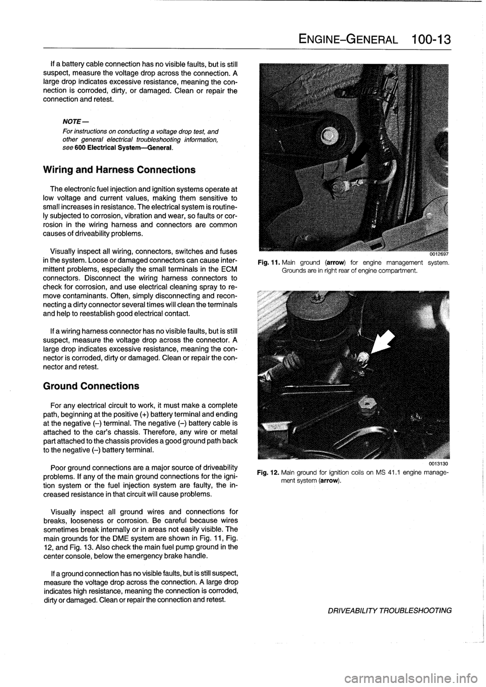
The
main
grounds
for
the
DME
system
are
shown
in
Fig
.
11,Fig
.
12,
and
Fig
.
13
.
Also
check
the
main
fuel
pump
ground
in
the
center
console,
below
the
emergency
brake
handle
.
If
a
ground
connection
has
no
visiblefaults,
but
is
still
suspect,
measure
the
voltage
drop
acrossthe
connection
.
A
large
drop
indicates
high
resistance,
meaning
the
connection
is
corroded,
dirty
or
damaged
.
Clean
or
repair
the
connection
and
retest
.
ENGINE-GENERAL
100-
1
3
UU,~uyi
Fig
.
11
.
Mainground
(arrow)
for
engine
management
system
.
Grounds
are
in
right
rear
of
engine
compartment
.
Fig
.
12
.
Mainground
for
ignition
coils
on
MS
41
.1
engine
manage-
ment
system
(arrow)
.
DRIVEABILITY
TROLIBLESHOOTING
Page 57 of 759
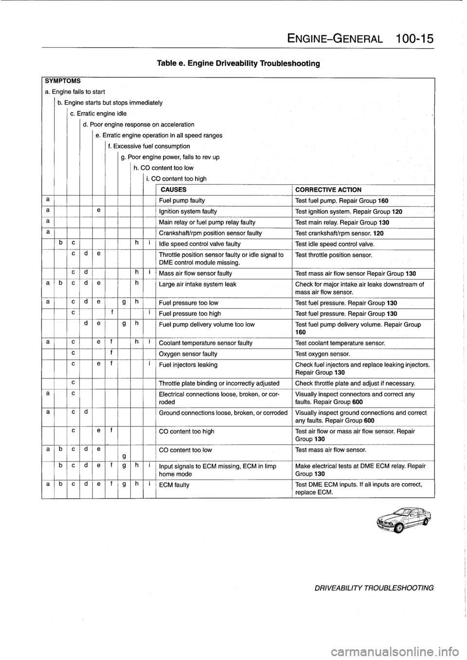
al
Icld
Table
e
.
Engine
Driveability
Troubleshooting
c
l
1
I
f
I
I
Oxygen
sensor
faulty
Test
oxygen
sensor
.
ENGINE-GENERAL
100-
1
5
SYMPTOMS
a
.
Engine
fafs
tostart
b
.
Engine
startsbut
stops
immediately
c
.
Erratic
engine
idle
d
.
Poor
engine
responseon
acceleration
e
.
Erratic
engine
operation
in
al¡
speed
ranges
f
.
Excessive
fuel
consumption
g
.
Poor
enginepower,
fails
to
rev
up
h
.
CO
content
toolow
i.
CO
content
too
high
CAUSES
CORRECTIVE
ACTION
a
Fuel
pump
faulty
Test
fuel
pump
.
Repair
Group
160
a
e
Ignition
system
faulty
Test
ignition
system
.
Repair
Group
120
a
Main
relay
or
fuel
pump
relay
faulty
Test
main
relay
.
Repair
Group
130
a
Crankshaft/rpm
position
sensor
faulty
Test
crankshaft/rpm
sensor
.
120
b
c
h
i
ldle
speed
control
valve
faulty
Test
idle
speed
control
valve
.
c
d
e
Throttle
position
sensor
faulty
or
idle
signal
to
Test
throttle
position
sensor
.
DME
control
module
missing
.
c
d
h
i
Mass
air
flow
sensor
faulty
Test
mass
air
flow
sensor
Repair
Group
130
a
b
c
d
e
h
Large
air
intake
system
leak
Check
for
major
intake
air
leaks
downstream
of
mass
air
flow
sensor
.
a
c
d
e
g
h
Fuel
pressure
too
low
Test
fuel
pressure
.
Repair
Group
130
?
I
F
ue
l
pr
essu
r
e
t
oo
high
T
est
f
u
el
pressure
.
Repair
Group
130
d
e
g
h
Fuel
pump
delivery
volume
too
low
Test
fuel
pump
delivery
volume
.
Repair
Group
160
a
c
e
f
h
q
C
oo
l
a
nt
t
e
mp
e
r
a
t
u
r
e
se
n
so
r
f
au
lty
--]
T
est
coo
l
a
n
t
temp
erature
sensor
.
c
e
~
f
i
~
Fuel
injectors
leaking
Check
fuel
injectors
and
replace
leaking
injectors
.
~
Repair
Group
130
Throttle
plate
binding
or
incorrectly
adjusted
Check
throttle
plate
and
adjust
if
necessary
.
a
c
Electrical
connections
loose,
broken,
or
cor-
Visually
inspect
connectors
and
correct
any
roded
faults
.
Repair
Group
600
Ground
connections
loose,
broken,
or
corroded
Visually
inspect
ground
connections
and
correct
any
faults
.
Repair
Group
600
c
e
~
f
CO
content
too
high
Test
air
flowor
mass
air
flow
sensor
.
Repair
~
Group
130
a
b
c
d
e
CO
content
too
low
Test
mass
air
flow
sensor
.
gb
c
d
e
f
g
h
i
Inputsignals
to
ECM
missing,
ECM
in
limp
Make
electrical
tests
at
DMEECM
relay
.
Repair
home
mode
Group
130
a
~
b
~
c
~
d
e]
f
g
h
i
ECM
faulty
Test
DMEECM
inputs
.
If
all
inputs
are
correct,
replace
ECM
.
DRIVEABILITY
TROUBLESHOOTING
Page 143 of 759
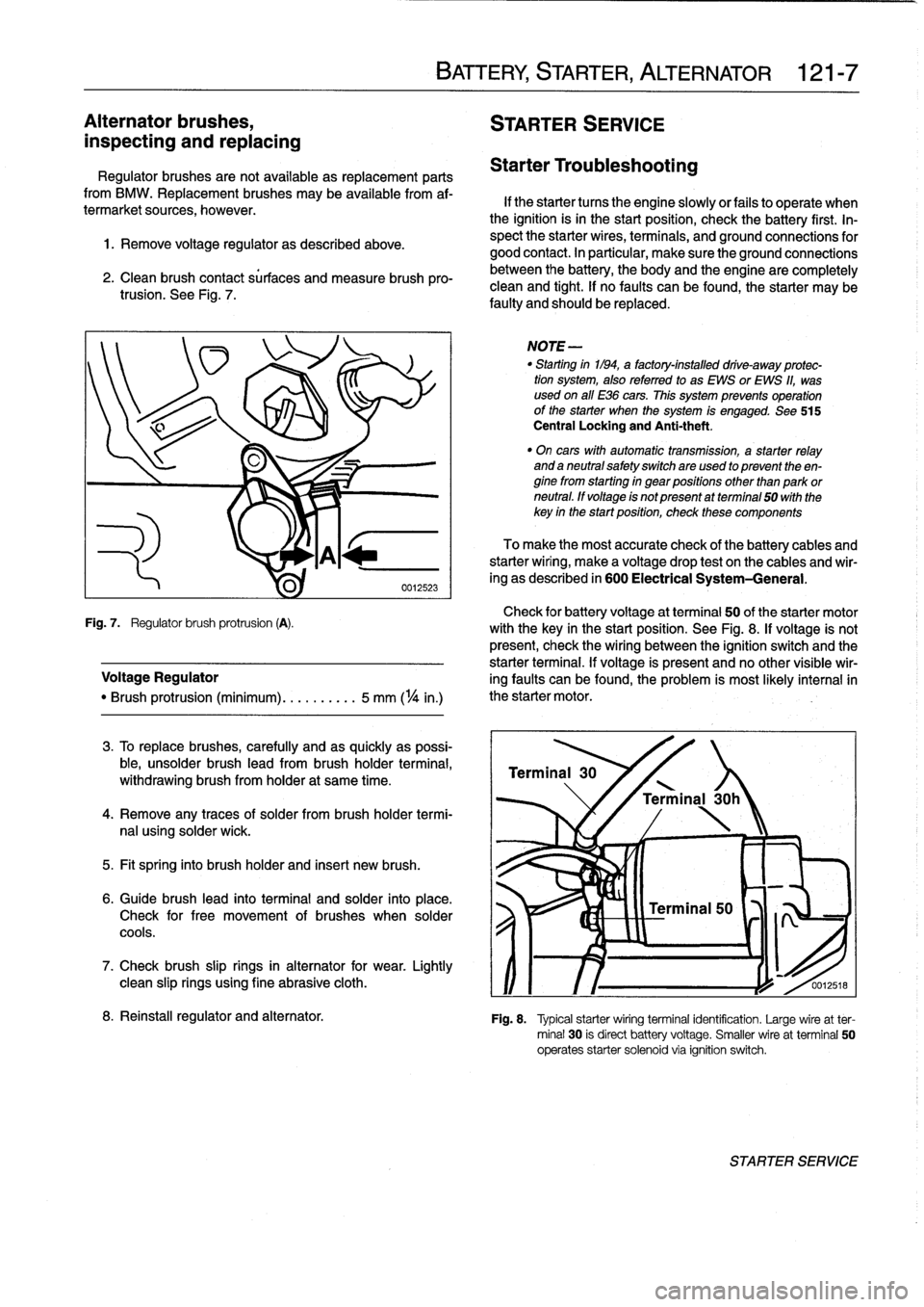
Alternator
brushes,
STARTER
SERVICE
inspecting
and
replacing
Regulator
brushesarenot
available
as
replacement
parts
from
BMW
.
Replacement
brushes
may
be
available
from
af-
termarket
sources,
however
.
1
.
Remove
voltage
regulator
as
described
above
.
2
.
Clean
brush
contact
sürfaces
and
measure
brush
pro-trusion
.
See
Fig
.
7
.
Check
for
battery
voltage
at
terminal
50
of
the
starter
motor
Fig
.
7
.
Regulator
brush
protrusion
(A)
.
with
the
key
in
the
start
position
.
See
Fig
.
8
.
If
voltage
is
not
present,
check
the
wiring
between
the
ignition
switch
and
the
starter
terminal
.
If
voltage
is
present
and
no
other
visible
wir
Voltage
Regulator
ing
faults
can
be
found,
the
problem
is
most
likely
interna¡in
"
Brush
protrusion
(minimum)
.......
.
..
5
mm
(
1
/4
in
.)
the
starter
motor
.
3
.
To
replace
brushes,
carefully
and
as
quickly
as
possi-
ble,
unsolder
brush
lead
from
brush
holder
termina¡,
withdrawing
brush
from
holder
at
same
time
.
4
.
Remove
any
traces
of
solder
frombrush
holder
termi-
nal
using
solder
wick
.
5
.
Fit
spring
into
brush
holder
and
inserí
new
brush
.
6
.
Guide
brush
lead
into
terminal
and
solder
into
place
.
Check
for
free
movement
of
brushes
when
solder
cools
.
7
.
Check
brush
slip
rings
in
alternator
for
wear
.
Lightly
clean
slip
rings
using
fine
abrasive
cloth
.
BATTERY,
STARTER,
ALTERNATOR
121-
7
Starter
Troubleshooting
If
the
starter
tucos
the
engine
slowlyor
fails
to
operate
when
the
ignition
isin
the
start
position,
check
the
battery
first
.
In-
spect
the
starter
wires,
terminals,
and
ground
connections
for
good
contact
.
In
particular,
make
sure
the
ground
connections
between
the
battery,
the
body
and
the
engine
are
completely
clean
and
tight
.
If
no
faults
can
be
found,
the
starter
may
be
faulty
and
should
be
replaced
.
NOTE
-
"
Starting
in1194,
a
factory-installed
drive-away
protec-
tion
system,
alsoreferred
to
as
EWS
or
EWS
11,
was
used
on
all
E36
cars
.
This
system
prevenís
operation
of
the
starter
when
the
system
is
engaged
.
See
515
Central
Locking
and
Anti-theft
.
"
On
cars
with
automatic
transmission,
a
starter
relay
and
a
neutral
safetyswitchare
used
to
present
theen-
ginefrom
starting
in
gear
positions
other
than
park
or
neutral
.
ff
voltage
is
not
present
atterminal
50
with
the
key
in
the
startposition,
check
these
components
To
make
the
most
accurate
check
of
the
battery
cables
and
starterwiring,
make
a
voltage
drop
test
on
the
cables
and
wir-
ing
as
described
in
600
Electrical
System-General
.
Terminal
30
'
\
/
Terminal
30h
0012518
8
.
Reinstall
regulator
and
alternator
.
Fig
.
8
.
Typical
starterwiring
terminal
identification
.
Large
wireat
ter-
minal
30
is
direct
battery
voltage
.
Smaller
wire
at
terminal
50
operates
starter
solenoid
via
ignition
switch
.
STARTER
SERVICE
Page 192 of 759
160-
8
FUEL
TANK
AND
FUEL
PUMP
UU131
tst5
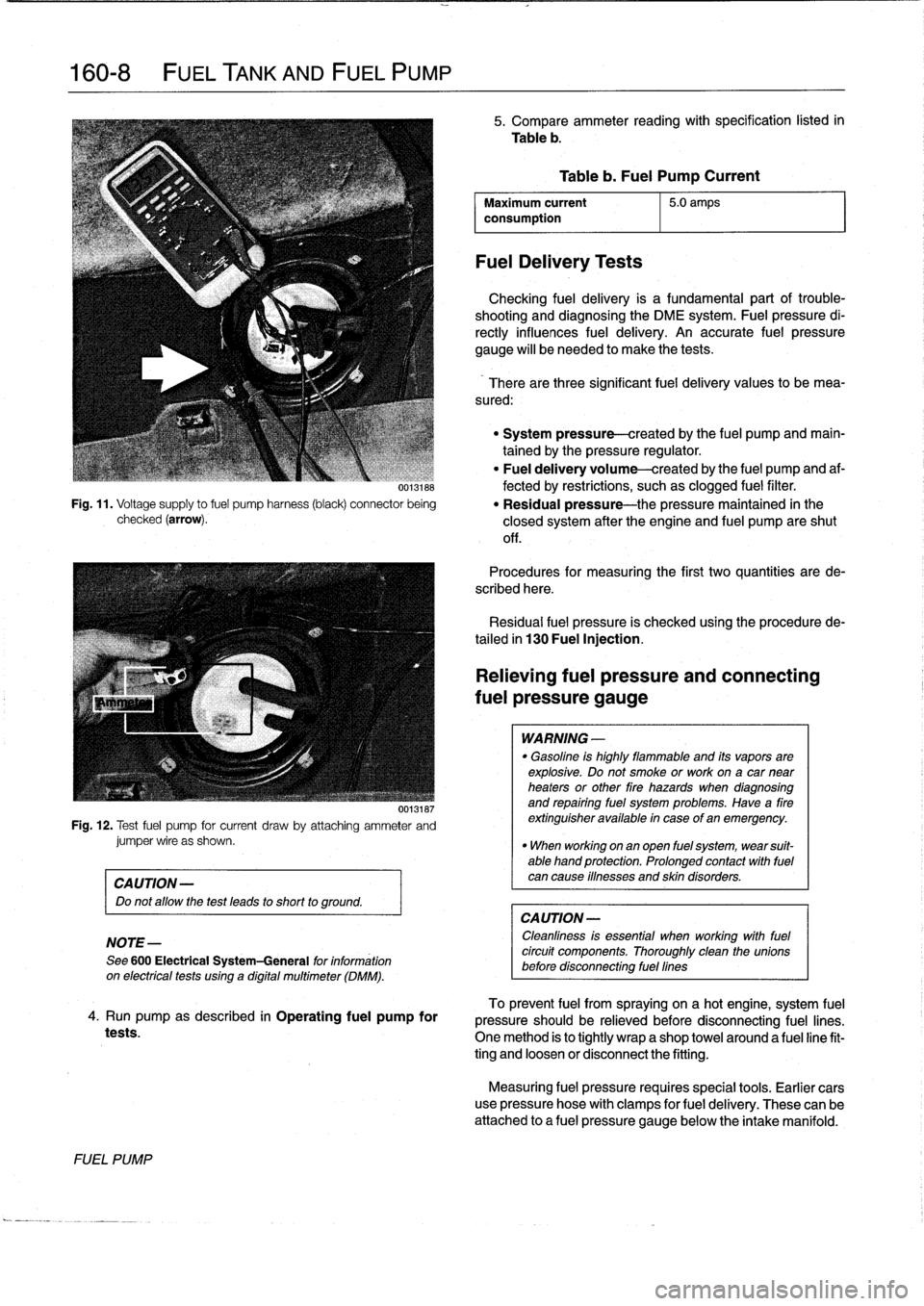
Fig
.
11
.
Voltage
supply
to
fuel
pump
harness
(black)
connector
being
checked
(arrow)
.
00131ts7
Fig
.
12
.
Test
fuel
pump
for
current
draw
by
attadhing
ammeter
andjumper
wire
as
shown
.
CAUTION-
Do
not
allow
the
test
leads
to
short
to
ground
.
NOTE-
See
600
Electrical
System-General
for
information
on
electricaltests
using
a
digital
multimeter
(DMM)
.
4
.
Run
pump
as
described
in
Operating
fuel
pump
for
tests
.
FUEL
PUMP
5
.
Compare
ammeter
reading
with
specification
listed
in
Table
b
.
Maximum
current
5
.0
amps
consumption
FuelDelivery
Tests
Table
b
.
Fuel
Pump
Current
Checking
fuel
delivery
is
a
fundamental
part
of
trouble-
shooting
and
diagnosing
the
DME
system
.
Fuelpressure
di-
rectly
influences
fuel
delivery
.
An
accurate
fuel
pressure
gauge
will
be
needed
to
make
the
tests
.
There
arethree
significant
fuel
delivery
values
to
bemea-
sured
:
"
System
pressure-created
by
the
fuel
pump
and
main-
tained
by
the
pressure
regulator
.
"
Fuel
delivery
volume-created
by
the
fuel
pump
and
af-
fected
by
restrictions,
suchas
clogged
fuel
filter
.
"
Residual
pressure-the
pressure
maintained
in
the
closed
system
after
the
engine
and
fuel
pump
areshut
off
.
Procedures
for
measuring
the
first
two
quantities
arede-
scribed
here
.
Residual
fuel
pressure
is
checked
using
the
procedurede-
tailed
in
130
Fuel
Injection
.
Relieving
fuel
pressure
and
connecting
fuel
pressure
gauge
WARNING
-
"
Gasoline
is
highly
flammable
and
its
vaporsare
explosive
.
Do
not
smoke
or
work
ona
car
near
heaters
or
other
fire
hazards
when
diagnosing
and
repairing
fuel
system
problems
.
Have
a
fire
extinguisher
available
in
case
of
an
emergency
.
"
When
working
onan
open
fuel
system,
wear
suit-
able
hand
protection
.
Prolonged
contact
with
fuel
can
cause
iflnesses
and
skin
disorders
.
CA
UTION-
Cleanliness
is
essential
when
working
withfuel
circuit
components
.
Thoroughly
clean
the
unionsbefore
disconnecting
fuel
fines
To
prevent
fuel
from
spraying
on
a
hotengine,
system
fuel
pressure
should
be
relieved
before
disconnecting
fuel
lines
.
One
method
is
to
tightly
wrap
a
shop
towel
around
a
fuel
line
fit-
ting
and
loosen
or
disconnect
the
fitting
.
Measuring
fuel
pressure
requires
special
tools
.
Earlier
cars
use
pressure
hose
with
clamps
for
fuel
delivery
.
These
can
be
attached
to
a
fuel
pressure
gauge
below
the
intake
manifold
.
Page 381 of 759
600
Electrical
System-General
GENERAL
.
...........
.
.
.
.
.
.
.
.
.
...
.
...
600-1
Voltage
and
Polarity
........
.
.
.
.
.
.
.
.....
600-1
Ming,
Fuses
and
Relays
............
.
.
.
.
600-1
Electrical
System
Safety
Precautions
...
.
.
.
.
600-1
Electrical
Test
Equipment
.....
.
.
.
....
.
.
.
.
600-2
WIRING
DIAGRAMS
..
.
.
.
.
.
.
.
.
.
........
600-2
Ming
Codes
and
Abbreviations
..
.
...
.
....
600-2
ELECTRICAL
TROUBLESHOOTING
..
.
..
600-3
Voltage
and
Voltage
Drops
..........
.
.
.
.
.
600-4
GENERAL
Electrical
System
Safety
Precautions
A
brief
description
of
the
principal
parts
of
the
electrical
sys-
tem
is
presented
here
.
Also
covered
here
are
basic
electrical
system
troubleshooting
tips
.
Voltage
and
Polarity
The
vehicle
electrical
system
is
a
12-volt
direct
current
(DC)
negative-ground
system
.
A
voltage
regulator
controls
system
voltage
at
approximately
the
12-volt
rating
of
the
battery
.
Al¡
circuits
are
grounded
by
direct
or
indirect
connection
to
the
negative
(-)
terminal
of
the
battery
.
A
number
of
ground
con-
nections
throughout
the
car
connect
the
wiring
harness
to
chassis
ground
.
These
circuits
are
completedby
the
battery
cable
or
ground
strap
between
the
body
and
the
battery
nega-
tive
(-)
terminal
.
Wiring,
Fuses
and
Relays
Nearly
all
parts
of
the
wiring
harnessconnect
to
compo-
nents
of
the
electrical
system
with
keyed,
push-on
connectors
that
lock
into
place
.
Notable
exceptions
arethe
heavy
battery
cables
and
the
starter
wiring
.
The
wiring
is
color-coded
for
cir-
cuitidentification
.
With
theexception
of
the
battery
charging
system,
most
electrical
power
is
routed
from
the
ignition
switch
or
the
bat-
tery
through
the
main
fuse/relay
panel,
located
in
¡he
left
rear
comer
of
the
engine
compartment
.
Fuses
are
color
coded
to
indicate
current
capacities
.
The
relays
and
control
units/modules
are
mounted
in
vari-
ous
places
throughout
the
vehicle
.
See610
Electrical
Com-
ponent
Locations
.
ELECTRICAL
SYSTEM-GENERAL
600-1
Voltage,
measuring
.
.
.
................
.
.
600-4
Voltage
drop,
testing
.
.
.....
.
.....
.
......
600-4
Continuity,
checking
..
.
...
.
.
.
.
.
.
.
.
.
.
.
.
.
.
.
600-5
Short
Circuits
.
.
.
.
.
.
.
.
.....
.
...
.
.
.
.
.
.
.
.
.
600-5
Short
circuit,
testing
with
ohmmete'r
.
.
.
.
.
.
.
.
.
600-6
Short
circuit,
testing
with
voitmeter
.
.
.
.
.
.
.
.
.
600-6
TABLES
a
.
Terminal
and
Circuit
Numbers
..............
..
.600-3
Please
read
the
following
warnings
and
cautions
before
do-
ing
any
work
on
your
electrical
system
.
WARNING
-
"
The
cars
covered
by
this
manual
are
equipped
with
aSupplemental
Restraint
System
(SRS)
that
automatically
deploys
one
or
more
airbags
.
Each
airbag
unit
houses
an
explosive
powerful
charge
.
Any
work
involving
the
SRS
system
should
only
be
performed
byan
authorized
BMW
dealer
.
Making
repairs
without
the
proper
knowledge
and
special
test
equipment
may
cause
serious
per-
sonal
injury
.
See
721
Airbag
System
(SRS)
.
"
The
ignition
system
of
the
car
operates
at
lethal
voltages
.
People
with
pacemakers
or
weak
hearts
should
not
expose
themselves
to
the
ignition
sys-
tem
.
Extra
caution
mustbe
taken
when
working
on
the
ignition
system
or
when
servicing
theen-
gine
while
it
is
runningor
the
key
is
on
.
See
120
Ignition
System
for
additional
ignition
system
warnings
and
cautions
.
"
Before
operating
the
starter
without
starting
the
engine
(as
when
making
a
compressfon
test),
dis-
able
the
ignition
system
as
described
in
120
Igni-
tion
System
.
"
Keep
hands,
clothing
and
other
objects
clear
of
the
electric
radiator
coollng
fan
when
working
on
a
warm
engine
.
The
fan
may
start
at
any
tíme,
even
when
the
ignition
is
switched
off
.
GENERAL
Page 382 of 759
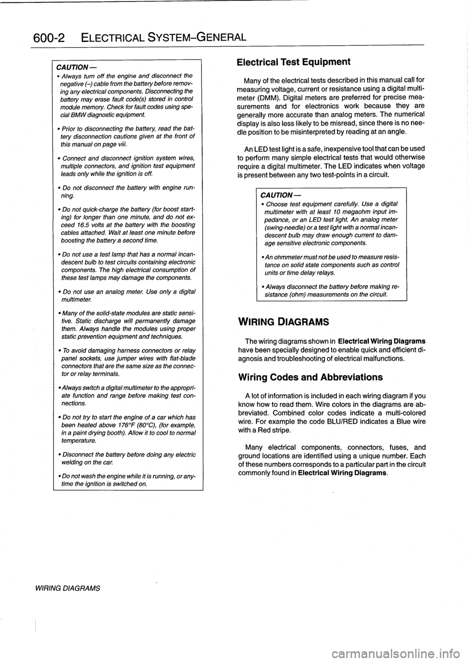
600-2
ELECTRICAL
SYSTEM-GENERAL
CAUTION
-
"
Always
turn
off
the
engine
and
disconnect
the
negative
()
cable
from
the
batterybefore
remov-
ing
any
electrical
components
.
Disconnecting
the
battery
may
erase
fault
code(s)
stored
in
control
module
memory
.
Check
for
fault
codes
using
spe-
cial
BMW
diagnostic
equipment
.
"
Prior
to
disconnecting
the
battery,
read
the
bat-
tery
disconnection
cautions
given
at
the
front
of
this
manual
onpage
viii
.
"
Connect
and
disconnect
ignition
system
wires,
multiple
connectors,
and
ignition
test
equipment
leads
only
while
the
ignition
is
off
.
"
Do
not
disconnect
the
battery
with
engine
run-
ning
.
"
Do
not
quick-charge
the
battery
(for
boost
start-
ing)
for
longer
than
one
minute,
and
do
not
ex-
ceed
16
.5
volts
at
the
battery
with
the
boosting
cables
attached
.
Wait
at
feast
one
minute
before
boosting
the
battery
a
second
time
.
"
Do
not
usea
test
famp
that
has
a
normal
incan-
descent
bulb
to
test
circuits
contafning
electronic
components
.
The
high
electrical
consumptionof
these
test
lamps
may
damage
the
components
.
"
Do
not
use
an
analog
meter
.
Use
onfy
a
digital
multimeter
.
"
Many
of
the
solid-state
modules
are
static
sensi-
tive
.
Static
discharge
will
permanently
damage
them
.
Always
handle
the
modules
using
proper
static
prevention
equipment
and
techniques
.
"
To
avoid
damaging
harness
connectors
or
relay
panel
sockets,
use
jumper
wires
with
flat-blade
connectors
that
are
the
same
size
as
the
connec-
tor
or
relay
terminals
.
"
Always
switch
a
digital
multimeter
to
the
appropri-
ate
function
and
range
before
making
test
con-
nections
.
"
Do
not
tryto
start
the
engine
of
a
carwhich
has
been
heated
above176°F
(80°C),
(for
example,
in
a
paint
dryingbooth)
.
Allow
it
to
cool
to
normal
temperature
.
"
Disconnect
the
battery
before
dolng
any
electric
welding
on
the
car
.
"
Do
not
wash
the
engine
while
it
is
runnfng,
or
any-
time
the
ignition
is
switched
on
.
WIRING
DIAGRAMS
Electrical
Test
Equipment
Many
of
the
electrical
tests
described
in
this
manual
call
for
measuring
voltage,
currentorresistanceusing
a
digital
multi-
meter
(DMM)
.
Digital
meters
are
preferred
for
precise
mea-
surements
and
for
electronics
work
because
they
are
generally
more
accuratethan
analog
meters
.
The
numerical
display
is
alsoless
likely
to
be
misread,
since
there
is
no
nee-
dle
position
to
be
misinterpreted
by
reading
at
an
angle
.
An
LED
test
light
is
a
safe,
inexpensive
tool
that
can
be
used
to
perform
many
simple
electrical
tests
that
would
otherwise
require
a
digital
multimeter
.
The
LED
indicates
when
voltage
is
present
between
anytwo
test-points
in
a
circuit
.
CA
UTION-
"
Choose
test
equipment
carefully
.
Use
a
digital
multimeter
with
at
leadt
10
megaohm
input
im-
pedance,or
an
LED
test
light
.
An
analog
meter
(swing-need1e)
ora
test
light
with
a
normal
incan-
descent
bulb
may
draw
enough
current
to
dam-
age
sensitive
electronic
components
.
"
An
ohmmeter
must
not
beused
to
measure
resis-
tance
on
solidstate
components
suchas
controlunits
or
time
delay
relays
.
"
Always
disconnect
the
battery
before
making
re-
sístance
(ohm)
measurements
on
the
circuit
.
WIRING
DIAGRAMS
The
wiring
diagrams
shown
in
Electrical
Wiring
Diagrams
have
been
specially
designed
to
enable
quick
and
efficientdi-
agnosis
and
troubleshooting
of
electrical
malfunctions
.
Wiring
Codes
and
Abbreviations
A
lot
of
information
is
included
in
each
wiring
diagram
if
you
know
how
to
read
them
.
Wire
colors
in
the
diagrams
are
ab-
breviated
.
Combined
color
codes
indicate
a
multi-colored
wire
.
For
example
the
code
BLU/RED
indicates
a
Blue
wire
with
a
Red
stripe
.
Many
electrical
components,
connectors,
fuses,
and
ground
locations
are
identified
using
a
unique
number
.
Each
of
there
numbers
corresponds
to
a
particular
part
in
the
circuit
commonly
found
in
Electrical
Wiring
Diagrams
.
Page 383 of 759
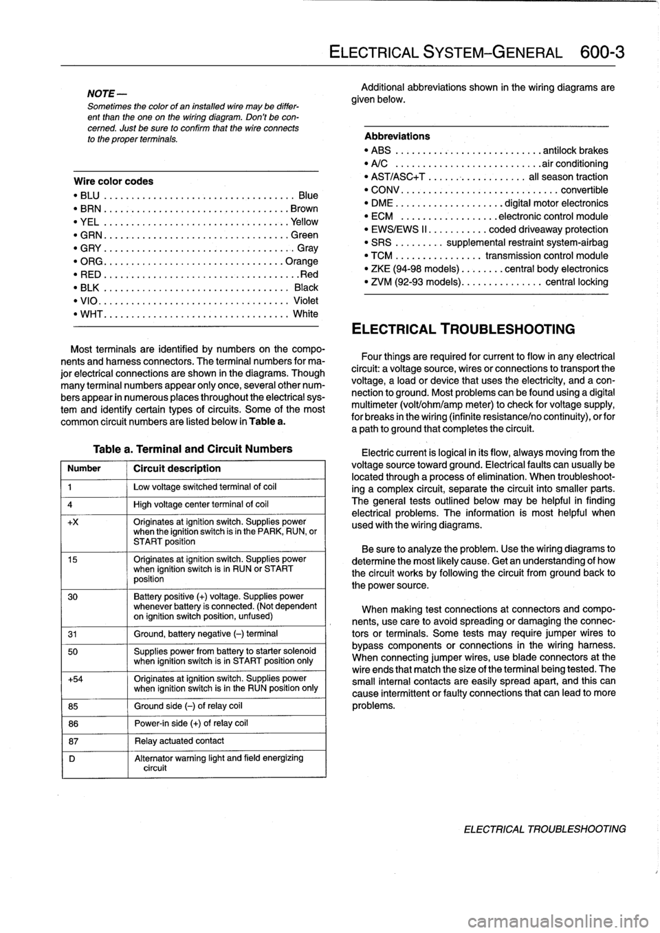
NOTE
-
Sometimes
the
color
of
en
installed
wire
may
be
differ-
ent
than
the
one
on
the
wiring
diagram
.
Don't
be
con-
cerned
.
Just
be
sure
lo
confirm
that
the
wire
connects
lo
the
proper
terminals
.
Wire
color
codes
"
BLU
.........
.
..
..
...
.
.................
Blue
"
BRN
....:....
.
..
..
...
..
...............
Brown
"
YEL
.........
.
..
..
...................
.Yellow
"
GRN
.........
.
..
..
...
.
................
creen
"
G
RY
.......
.
.
.
..
..
.....................
G
ray
"
ORG
.........
.
..
..
...
.
..............
.Orange
"
RED
......
...
.
.
..
.....................
.Red
"
BLK
.........
.
..
..
...
.
................
Black
"
VIO
..........
.
..
...
..
..
.......
.
.......
Violet
"
WHT
.........
.
.
....
.
...
:..............
White
Table
a
.
Terminal
and
Circuit
Numbers
Number
1
Circuít
description
1
j
Low
voltage
switched
terminal
of
coi¡
4
1
High
voltage
center
termina¡
of
coi¡
+x
Originates
atignition
switch
.
Supplies
powerwhen
the
ignition
switch
is
in
the
PARK,
RUN,
or
START
position
15
Originates
atignition
switch
.
Supplies
powerwhen
ignition
switch
is
in
RUN
or
START
position
30
Battery
positive
(+)
voltage
.
Supplies
power
whenever
battery
is
connected
.
(Not
dependent
on
ignition
switch
position,
unfused)
31
1
Ground,
battery
negative
(-)
terminal
50
Supplies
power
from
battery
to
starter
solenoid
when
ignition
switch
isin
START
position
only
+54
Originates
atignition
switch
.
Supplies
power
when
ignition
switch
isin
the
RUN
position
only
85
1
Ground
side
(-)
ofrelay
coil
86
1
Power-in
side
(+)
ofrelay
coil
87
1
Relay
actuatedcontact
D
Alternator
warning
light
and
field
energizing
circuit
ELECTRICAL
SYSTEM-GENERAL
600-
3
Additional
abbreviations
shown
in
the
wiring
diagrams
are
given
below
.
Abbreviations
"
ABS
........
.
...
.
...
.
..........
antilock
brakes
"
A/C
........
.
...
..
..
.
.........
.airconditioning
"
AST/ASC+T
.......
...
.
.
.......
al¡
season
traction
"
CONV
.......
.
.
...
.................
convertible
"
DME
........
.
.
...
.......
digital
motor
electronics
"
ECM
.......
.
...
..
..
.
..
electronic
control
module
"
EWS/EWS
II
......
...
.
.
coded
driveaway
protection
"
SRS
........
.
supplemental
restraint
system-airbag
"
TCM
........
.
..
....
.
transmission
control
module
"
ZKE
(94-98
models)
..
..
.
...
central
body
electronics
"
ZVM
(92-93
models)
...
.
.
..
.
.......
central
locking
ELECTRICAL
TROUBLESHOOTING
Most
terminals
are
identified
by
numbers
on
the
compo-
nents
and
harness
connectors
.
The
terminal
numbers
for
ma-
Four
things
are
required
for
current
toflow
in
any
electrical
jor
electrical
connections
are
shown
in
the
diagrams
.
Though
circuit
:
a
voltagesource,
wires
or
connections
to
transport
the
many
terminal
numbers
appear
only
once,
severa¡other
num-
voltage,
a
load
or
device
that
uses
the
electricity,
and
a
con-
bers
appear
in
numerous
places
throughout
the
electrical
sys-
nection
to
ground
.
Most
problemscanbefound
using
a
digital
tem
and
identify
certain
types
ofcircuits
.
Some
of
the
most
multimeter
(volt/ohm/amp
meter)to
check
for
voltage
supply,
common
circuit
numbers
are
listed
below
in
Table
a
.
for
breaks
in
the
wiring
(infinite
resistance/no
continuity),
orfor
a
path
to
ground
that
completesthe
circuit
.
Electric
current
is
logical
in
its
flow,
always
moving
from
the
voltage
sourcetoward
ground
.
Electricalfaults
can
usually
be
located
through
a
process
of
elimination
.
When
troubleshoot-
ing
a
complex
circuit,
separate
the
circuit
into
smaller
parts
.
The
general
testsoutlined
below
may
be
helpful
in
finding
electrical
problems
.
The
information
is
most
helpful
when
used
with
the
wiring
diagrams
.
Be
sure
to
analyze
the
problem
.
Use
the
wiring
diagrams
to
determine
the
most
likely
cause
.
Getan
understanding
of
how
the
circuit
works
by
following
the
circuit
from
groundback
to
the
power
source
.
When
making
test
connections
at
connectors
andcompo-
nents,
use
care
to
avoidspreading
or
damaging
the
connec-
tors
or
terminals
.
Some
tests
may
require
jumper
wires
to
bypass
components
or
connections
in
the
wiring
harness
.
When
connecting
jumper
wires,
use
bladeconnectors
at
the
wire
ends
that
match
the
size
of
the
terminal
being
tested
.
The
small
interna¡
contacts
are
easily
spread
apart,
and
this
can
cause
intermittent
or
faultyconnections
that
can
leadto
more
problems
.
ELECTRICAL
TROUBLESHOOTING