Automatic shift lever BMW 325i 1992 E36 Workshop Manual
[x] Cancel search | Manufacturer: BMW, Model Year: 1992, Model line: 325i, Model: BMW 325i 1992 E36Pages: 759
Page 215 of 759
GENERAL
..
.
.
.
.
.
.
.
.
.
.
.
.
.
......
.
......
210-1
CLUTCH
MECHANICAL
.
.
.
.
.
...
.
.....
.
.
210-3
CLUTCH
HYDRAULICS
.
.
.
.............
210-1
Clutch,
removing
.
.
.
.
.
.
.
.
.
.
.
.
.
.
.
.
...
.
.
.
.
210-4
Clutch,inspecting
and
installing
.
.
.
.
.
.
.
.
.
.
.
.210-5Clutch
hydraulic
system,
Transmission
pilot
bearing,replacing
.
.
.
.
...
210-6
bleeding
and
flushing
.
.
.
.
.
.......
.
.....
210-2
Clutch
master
cylinder,
replacing
..
.
.
.
.
.
...
210-2
Table
Clutch
slave
cylinder,
replacing
...
.
.
.
.
.
.
.
.
210-3
a
.
Clutch
Disc
Diameter
.............
..
..
.
......
210-3
GENERAL
CLUTCH
HYDRAULICS
This
repair
group
covers
replacement
of
the
clutch
mechan-
The
Clutch
is
hydraulically
actuated
by
the
master
and
slave
¡cal
and
hydraulic
components
.
Special
tools
may
be
required
cylinders
.
Clutch
disc
wear
is
automatically
taken
upby
the
for
some
of
the
procedures
.
Read
the
procedure
through
be-
pushrod
travelof
the
slave
cylinder,
making
periodic
adjust-fore
beginning
a
job
.
ments
unnecessary
.
NOTE-
See200
Transmission-General
for
transmission
applicatíon
information
.
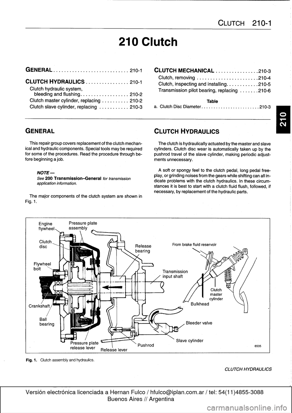
The
major
components
of
the
clutch
system
are
shown
in
Fig
.
1
.
Engine
Pressure
plate
flywheel,,
assembly
Clutch
Flywheel
bolt
Pressure
plate
release
lever
Release
lever
Fig
.
1
.
Clutch
assembly
and
hydraufcs
.
210
Clutch
Release
bearing
Pushrod
A
soft
or
spongy
feel
to
the
clutchpedal,
long
pedal
free-
play,
or
grinding
noises
from
thegears
while
shifting
can
all
in-
dicate
problems
with
the
Clutch
hydraulics
.
In
these
circum-
stances
it
is
best
to
start
with
a
clutch
fluid
flush,
followed,
if
necessary,
byreplacement
of
the
hydraulic
parts
.
From
brake
fluid
reservoir
CLUTCH
210-1
0
0
Transmission
inputshaft
Clutch
master
cylinder
Bulkhead
Slave
cylinder
6535
CLUTCH
HYDRAULICS
Page 232 of 759
240-
4
AUTOMATIC
TRANSMISSION
TRANSMISSION
REMOVALAND
INSTALLATION
Removal
and
installation
of
thetransmission
is
best
accom-
plished
on
a
lift
using
a
transmission
jack
.
Use
caution
and
safe
workshop
practices
when
working
beneath
car
and
low-
ering
transmission
.
WARNING
-
To
lift
the
vehicle
safely,
see010
Fundamentals
for
the
Do-it-Yourself
Owner
.
CAUTION-
"
Be
sure
the
vehicle
is
properly
supported
.
The
removal
of
the
transmission
may
upset
the
bal-
ance
of
the
vehicle
on
a
lift
.
"
Tilting
the
engine
to
remove
the
transmission
can
lead
to
damage
to
various
components
due
to
lack
of
clearance
.
-On
carswith
AST
remove
throttle
body
.
-Remove
brake
fluid
reservoir
if
necessary
.
Torx-head
bolts
are
used
to
mount
thetransmission
to
the
bellhousing
.
Be
sure
to
have
appropriate
tools
on
hand
before
starting
thejob
.
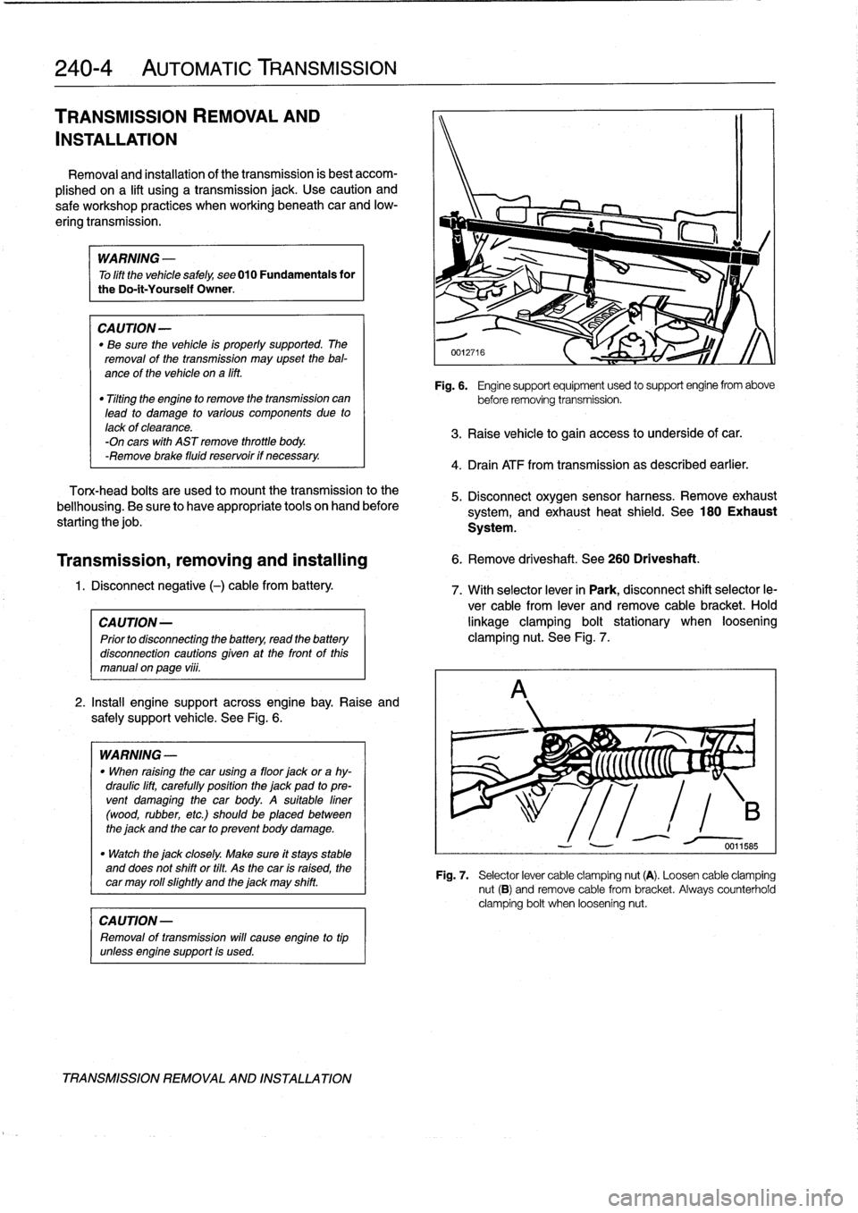
2
.
Install
engine
support
across
engine
bay
.
Raise
and
safely
support
vehicle
.
See
Fig
.
6
.
WARNING
-
"
When
raising
thecar
using
a
floor
jack
or
a
hy-
draulic
lift,
carefully
position
the
jack
pad
to
pre-
vent
damaging
the
car
body
.
A
suitable
liner
(wood,
rubber,
etc
.)
should
be
placed
between
the
jack
and
the
car
to
prevent
body
damage
.
"
Watch
the
jack
closely
.
Make
sure
it
stays
stable
and
does
not
shift
or
tilt
.
As
the
car
is
raised,
the
car
may
roll
slightty
and
the
jack
may
shift
.
CAUTION-
Removal
of
transmission
will
cause
engine
to
tip
unlessengine
support
is
used
.
TRANSMISSION
REMOVAL
AND
INSTALLATION
Fig
.
6
.
Engine
support
equipment
used
to
support
engine
from
above
before
removing
transmission
.
3
.
Raise
vehicle
to
gain
access
to
underside
of
car
.
4
.
Drain
ATF
from
transmission
as
described
earlier
.
5
.
Disconnect
oxygen
sensor
harness
.
Remove
exhaust
system,
and
exhaust
heat
shield
.
See
180
Exhaust
System
.
Transmission,
removing
and
installing
6
.
Remove
driveshaft
.
See
260
Driveshaft
.
1
.
Disconnect
negative
(-)
cable
from
battery
.
7
.
With
selector
lever
in
Park,
disconnect
shift
selector
le-
ver
cable
from
lever
and
remove
cable
bracket
.
Hold
CA
UTION-
linkage
clamping
bolt
stationary
when
loosening
Prior
to
disconnectiog
the
battery,
read
the
battery
clamping
nut
.
See
Fig
.
7
.
disconnection
cautions
given
at
the
front
of
this
manual
on
page
vi¡¡
.
Fig
.
7
.
Selector
lever
cable
clamping
nut
(A)
.
Loosen
cable
clamping
nut
(B)
and
remove
cable
from
bracket
.
Always
counterholdclamping
bolt
when
loosening
nut
.
Page 235 of 759
GENERAL
.
.
.
.
.
.
.
.
.
................
.
.
.
250-1
AUTOMATIC
TRANSMISSION
GEARSHIFT
...
.
.........
.
.
.
.
.
.
.
.
.
.
.
.
.
.
250-3
MANUAL
TRANSMISSION
Gearshift
mechanism,
adjusting
GEARSHIFT
.
.
.
.
.
.
.
.....
.
..........
.
.
.
250-1
(automatictransmission)
..
.
.
.
.
.
.
.
.
.
...
.
.
250-3
Gearshift
lever,
removing
Gear
position/neutral
safety
switch,
replacing
(manual
transmission)
.
.
.
.
...
.
.
.
.......
250-1
(automatic
transmission)
..
.
.
.
.........
.
.
250-4
Gearshift
lever,
installing
Automatic
shiftlock,
checking
function
(manual
transmission)
.
.
.
.
.
.
.
.
.
.
.......
250-2
(automatic
transmission)
..
..
...
.
.
.
....
..
250-5
Shiftinterlock,
checking
function
(automatic
transmission)
.......
.
.
.
.....
.250-6
GENERAL
This
repair
group
covers
transmission
gearshift
and
linkage
service
.
Special
service
tools
are
required
for
some
of
the
proce-
dures
given
here
.
To
gain
access
to
the
complete
gearshift
mechanism
ít
is
necessary
to
remove
the
exhaust
system
and
the
driveshaft
as
described
in
180
Exhaust
System
and260
Driveshaft
.
MANUAL
TRANSMISSION
GEARSHIFT
Gearshift
lever,
removing
(manual
transmission)
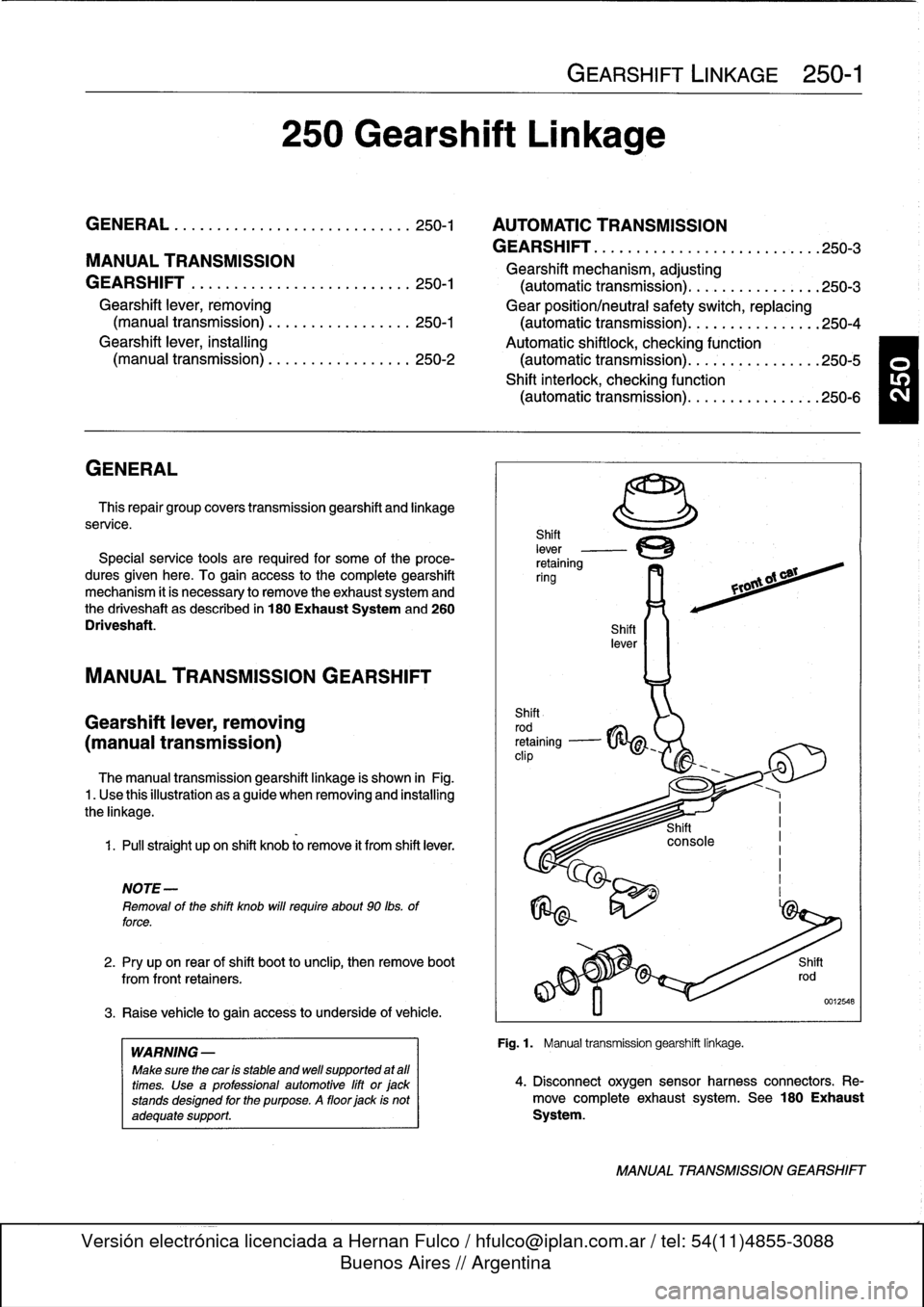
The
manual
transmission
gearshift
linkage
is
shown
in
Fig
.1
.
Use
thisillustration
asaguide
when
removing
and
installing
the
linkage
.
1
.
Pull
straight
upon
shift
knob
lo
remove
it
from
shift
lever
.
NOTE
-
Removal
of
the
shift
knob
will
require
about
90
lbs
.
of
force
.
2
.
Pry
upon
rear
of
shift
boot
tounclip,
then
remove
boot
from
front
retainers
.
3
.
Raise
vehicle
togain
access
to
underside
of
vehicle
.
WARNING
-
Make
sure
thecar
is
stable
and
well
supported
at
afl
times
.
Use
a
professional
automotive
lift
orjackstands
designed
for
the
purpose
.
A
floor
jack
is
not
adequate
support
.
250
Gearshift
Linkage
GEARSHIFT
LINKAGE
250-1
Fig
.1
.
Manual
transmission
gearshift
linkage
.
4
.
Disconnect
oxygen
sensorharness
connectors
.
Re-
move
completeexhaust
system
.
See
180
Exhaust
System
.
MANUAL
TRANSMISSION
GEARSHIFT
Page 237 of 759
2
.
Install
rubber
grommet
with
arrow
pointing
forward
.
In-
AUTOMATic
TRANSMISSION
stall
shift
rod
and
shift
boot
.
GEARSHIFT
NOTE-
Install
rubbergrommet
correctly
so
that
is
seals
outwa-
ter
.
4
.
Install
driveshaft
and
heat
shield
.
See
260
Driveshaft
.
Manual
valveleven
(at
transmission)
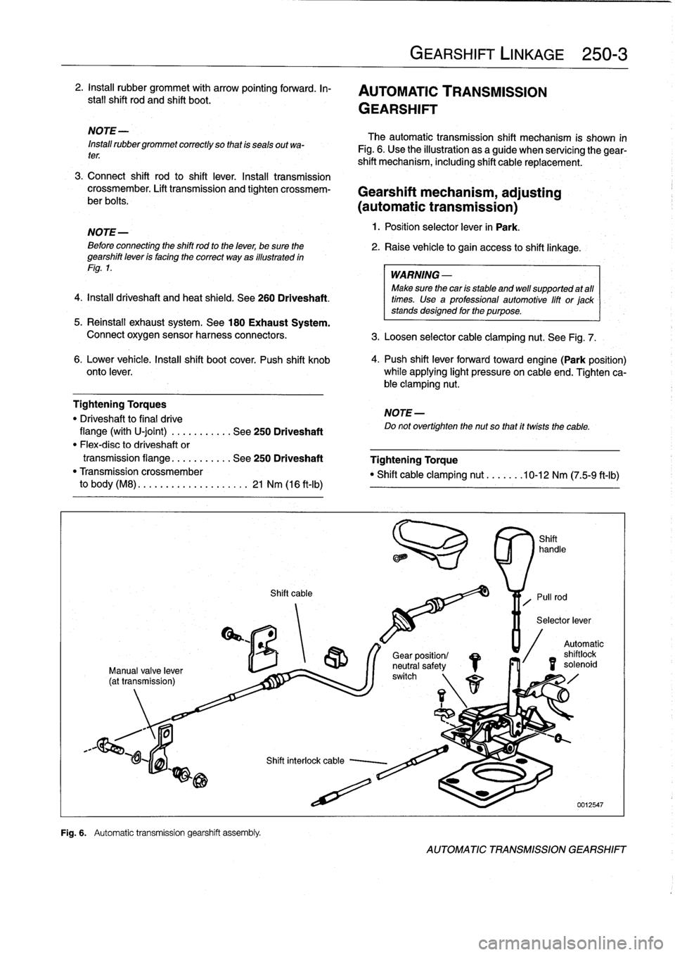
Fig
.
6
.
Automatic
transmission
gearshift
assembfy
.
Shift
cable
GEARSHIFT
LINKAGE
250-
3
The
automatic
transmission
shift
mechanism
is
shown
in
Fig
.
6
.
Use
the
illustration
as
a
guide
when
servícing
the
gear-
shift
mechanism,
including
shift
cable
replacement
.
3
.
Connect
shift
rod
to
shift
lever
.
Install
transmission
crossmember
.
Lift
transmission
and
tighten
crossmem-
Gearshift
mechanism,
adjusting
ber
bolts
.
(automatictransmission)
NOTE-
1
.
Position
selector
lever
in
Park
.
Beforeconnecting
the
shift
rod
to
the
lever,
be
sure
the
2
.
Raise
vehicle
to
gain
access
to
shift
linkage
.
gearshift
leven
is
facing
the
correct
way
as
illustrated
in
Fig
.
1
.
WARNING
-
Make
sure
thecan
is
stable
and
well
supported
at
all
times
.
Use
a
professional
automotive
lift
or
jack
stands
designed
for
the
purpose
.
5
.
Reinstall
exhaust
system
.
See
180
Exhaust
System
.
Connect
oxygen
sensor
harness
connectors
.
3
.
Loosen
selector
cable
clamping
nut
.
See
Fig
.
7
.
6
.
Lower
vehicle
.
Insta¡¡
shift
boot
cover
.
Push
shift
knob
4
.
Push
shift
lever
forwardtoward
engine(Park
position)
onto
lever
.
while
applying
light
pressure
on
cable
end
.
Tighten
ca-
ble
clamping
nut
.
Tightening
Torques
NOTE-
"
Driveshaft
to
final
drive
Do
not
overtighten
the
nut
so
that
it
twists
the
cable
.
flange
(with
U-joint)
.
..
.
.....
.
.
See
250
Driveshaft
"
Flex-disc
to
driveshaft
or
transmission
flange
...
.
.......
See
250
Driveshaft
Tightening
Torque
"
Transmission
crossmember
"
Shift
cable
clamping
nut
.......
10-12
Nm
(75-9
ft-Ib)
to
body
(M8)
.
.
.
...
..............
21
Nm
(16
ft-Ib)
/S
r\
1
1
Gear
position/
neutral
safetyswitch
Automatic
shilo
solenoid
id
AUTOMATIC
TRANSMISSION
GEARSHIFT
Page 238 of 759
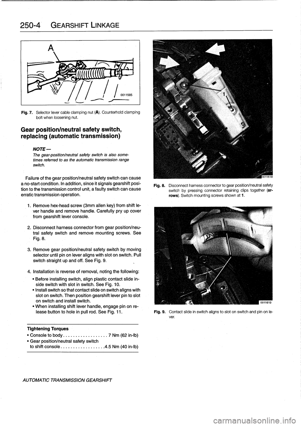
250-
4
GEARSHIFT
LINKAGE
r%
;
5
(((((C
"
~
;
Fig
.
7
.
Selector
lever
cable
clamping
nut
(A)
.
Counterhold
clamping
bolt
when
loosening
nut
.
Gear
position/neutral
safety
switch,
replacing
(automatic
transmission)
NOTE-
The
gear-positionlneutral
safetyswitch
is
also
some-
times
referred
to
as
the
automatic
transmission
range
switch
.
Failure
of
the
gear
positionlneutral
safetyswitch
can
cause
a
no-start
condition
.
In
acidition,
since
it
signals
gearshift
posi-
tion
tothe
transmission
control
unit,
a
faulty
switch
can
cause
erratic
transmission
operation
.
1
.
Remove
hex-head
screw
(3mm
allen
key)
from
shift
le-
ver
handle
and
remove
handle
.
Carefully
pry
up
cover
from
gearshift
lever
console
.
2
.
Disconnect
harness
connector
from
gear
positionlneu-
tral
safety
switch
andremove
mounting
screws
.
See
Fig
.
8
.
3
.
Remove
gear
positionlneutral
safety
switch
by
moving
selector
until
pin
on
lever
aligns
with
slot
on
switch
.
Pull
switch
straight
up
and
off
.
See
Fig
.
9
.
4
.
Installation
is
reverse
of
removal,
noting
the
following
:
"
Before
installing
switch,
align
plastic
contact
slide
in-
sideswitch
with
slot
in
switch
.
See
Fig
.
10
.
"
Instan
switch
so
that
contact
slide
on
switch
aligns
with
slot
on
switch
.
Then
position
gearshift
lever
pin
to
slot
on
switch
and
install
switch
.
"
When
installing
shift
lever
handle,
engage
pín
on
re
leasebutton
to
hole
in
pulí
rod
.
See
Fig
.
11
.
Fig
.
9
.
Contact
slide
in
switch
aligns
toslot
on
switch
and
pin
on
le-
ver
.
Tightening
Torques
"
Console
to
body
..............
...
.
7
Nm
(62
in-lb)
"
Gear
positionlneutral
safety
switch
to
shift
console
.................
.
4
.5
Nm
(40
in-lb)
AUTOMATIC
TRANSMISSION
GEARSHIFT
Fig
.
8
.
Disconnect
harness
connector
to
gear
position/neutral
safety
switch
by
pressing
connector
retaining
clips
together
(ar-
rows)
.
Switch
mountingscrews
shown
at
1
.
Page 239 of 759
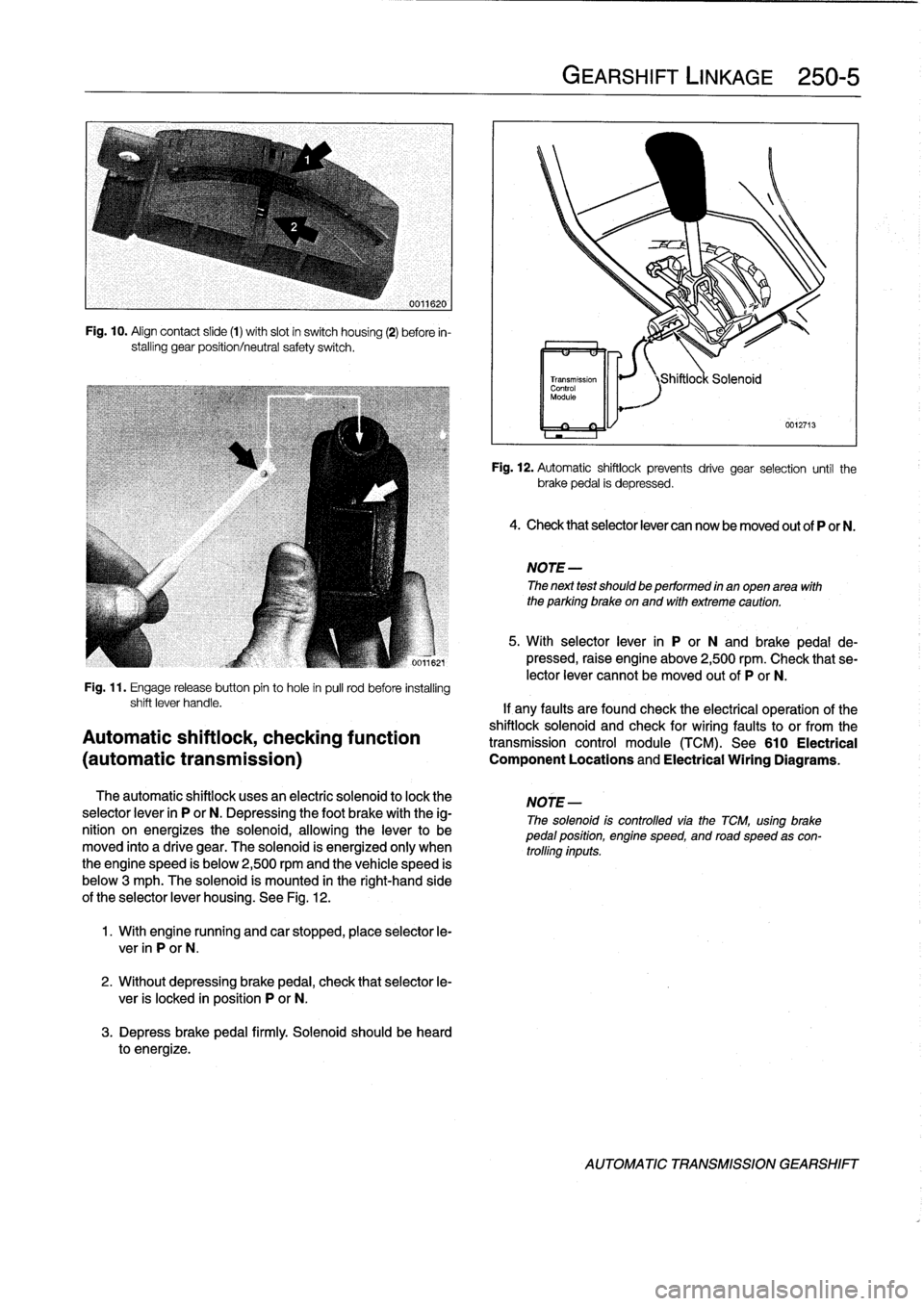
Fig
.
10
.
Align
contact
slide
(1)
with
slot
in
switch
housing
(2)
before
in-
stalling
gear
position/neutral
safety
switch
.
Fig
.
11
.
Engage
release
button
pin
to
hole
in
pull
rod
before
installing
The
automatic
shiftlock
uses
an
electríc
solenoid
to
lock
the
selector
lever
in
P
or
N
.
Depressing
the
foot
brake
withthe
ig-
nition
on
energizes
the
solenoid,
allowingthe
lever
to
be
moved
into
a
drive
gear
.
The
solenoid
is
energized
only
when
the
engine
speed
is
below
2,500
rpmand
thevehicle
speed
is
below
3
mph
.
The
solenoid
ís
mounted
in
the
right-hand
side
of
theselector
lever
housing
.
See
Fig
.
12
.
1
.
With
engine
running
and
car
stopped,
place
selector
le-
ver
in
P
or
N
.
2
.
Without
depressing
brake
pedal,
check
that
selector
le-
ver
is
locked
in
position
P
or
N
.
3
.
Depress
brakepedal
firmly
.
Solenoid
should
be
heard
to
energize
.
GEARSHIFT
LINKAGE
250-
5
Fig
.
12
.
Automatic
shiftlock
prevents
drive
gear
selection
until
the
brakepedal
is
depressed
.
4
.
Check
thatselector
lever
can
now
be
moved
out
of
P
or
N
.
NOTE
-
The
next
test
should
be
performed
in
anopen
area
with
the
parking
brake
on
and
with
extreme
caution
.
5
.
With
selector
lever
in
P
or
N
and
brake
pedal
de-
pressed,
raise
engine
above
2,500
rpm
.
Check
that
se-
lector
lever
cannotbe
moved
outof
P
or
N
.
shift
lever
handle
.
If
any
faults
are
found
check
the
electrical
operation
of
the
shiftlock
solenoid
and
check
for
wiring
faultsto
or
from
the
Automatic
shiftiock,
checking
function
transmission
control
module(TCM)
.
See610
Electrical
(automatic
transmission)
Component
Locations
and
Electrical
Wiring
Diagrams
.
NOTE
-
The
solenoid
is
controlled
viathe
TCM,
using
brakepedal
position,
engine
speed,
and
road
speed
as
con-
trolling
inputs
.
AUTOMATIC
TRANSMISSION
GEARSHIFT
Page 240 of 759
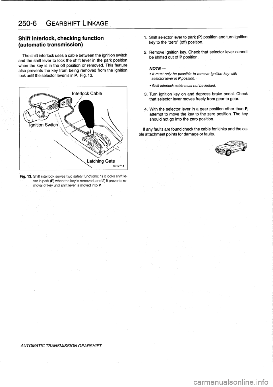
250-
6
GEARSHIFT
LINKAGE
Shift
interlock,
checking
function
1
.
Shift
selectorlever
to
park
(P)
position
and
turn
ignition
(automatic
transmission)
The
shift
interlock
usesa
cable
between
the
ignition
switch
and
the
shift
lever
to
lock
the
shift
lever
in
the
park
position
when
the
key
is
in
the
off
position
or
removed
.
This
feature
also
prevents
the
key
from
being
removed
from
the
ignition
lock
until
the
selectorlever
is
in
P
.
Fig
.
13
.
Fig
.
13
.
Shift
interlock
serves
two
safety
functions
:
1)
it
locks
shift
le-
ver
in
park
(P)
when
thekey
is
removed,
and
2)
it
prevents
re-
moval
of
key
untilshift
lever
is
moved
into
P
.
AUTOMATIC
TRANSMISSION
GEARSHIFT
Latchirig
Gate
0012714
key
to
the
"zero"
(off)
position
.
2
.
Remove
ignition
key
.
Check
that
selectorlever
cannot
be
shifted
out
of
P
position
.
NOTE-
"
lt
must
only
be
possible
to
remove
ignition
key
with
selector
lever
in
P
position
.
"
Shiftinterlock
cable
must
not
be
kinked
.
3
.
Turn
ignition
keyon
and
depressbrakepedal
.
Check
that
selectorlever
moves
freely
from
gear
to
gear
.
4
.
With
the
selectorlever
in
a
gear
position
other
than
P,
attempt
to
move
thekey
to
the
zero
position
.
The
key
shouldnot
go
into
the
zero
position
.
If
any
faults
arefound
check
the
cable
for
kinks
and
theca-
ble
attachment
points
for
damage
or
faults
.
Page 397 of 759
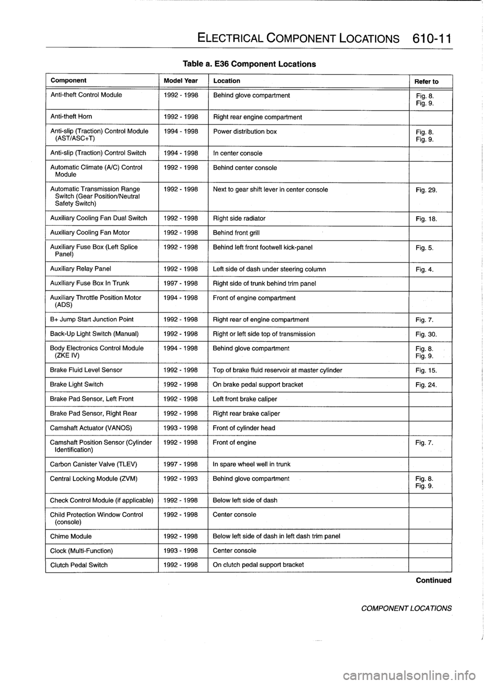
Table
a
.
E36
Component
Locations
Component
Model
Year
Location
Refer
to
Anti-theft
Control
Module
1992-1998
Behind
glove
compartment
Fig
.
8
.
Fig
.
9
.
Anti-theft
Horn
1
1992-1998
1
Right
rear
engine
compartment
Anti-slip
(Traction)
Control
Module
1994-1998
Power
distribution
box
Fig
.
8
.
(AST/ASC+T)
Fig
.
9
.
Anti-slip
(Traction)
Control
Switch
1994-1998
In
center
console
Automatic
Climate
(A/C)
Control
1992-1998
Behind
center
console
Module
AutomaticTransmission
Range
1992-1998
~
Next
to
gear
shift
lever
in
center
console
Fig
.
29
.
Switch
(Gear
Position/Neutral
Safety
Switch)
Auxiliary
Cooling
Fan
Dual
Switch
1992-1998
Right
side
radiator
1
Fig
.
18
.
Auxiliary
Cooling
Fan
Motor
1992-1998
Behind
front
grill
Auxiliary
Fuse
Box
(Left
Splice
1992-1998
I
Behind
left
front
footwell
kick-panel
Panel)
Auxiliary
RelayPanel
1
1992-1998
1
Left
side
of
dash
under
steering
column
Auxiliary
Fuse
Box
In
Trunk
1
1997-1998
1
Right
sideof
trunk
behind
trim
panel
AuADSry
ThrottlePosition
Motor
11994-1998
Front
of
engine
compartment
B+
Jump
Start
Junction
Point
1992-1998
Right
rear
of
engine
compartment
Fig
.
7
.
Back-Up
Light
Switch
(Manual)
1992-1998
Right
or
left
side
top
of
transmission
Fig
.
30
.
Body
Electronics
Control
Module
1994-1998
Behindglove
compartment
Fig
.
8
.
(ZKE
IV)
Fig
.
9
.
Brake
Fluid
Level
Sensor
1992-1998
Top
of
brake
fluid
reservoir
at
master
cylinder
Fig
.
15
.
Brake
Light
Switch
1
1992-1998
1
On
brake
pedal
supportbracket
Brake
Pad
Sensor,
Left
Front
1
1992-1998
1
Left
front
brake
caliper
Brake
Pad
Sensor,
Right
Rear
1992-1998
Right
rear
brake
caliper
Camshaft
Actuator
(VANOS)
1993-1998
Front
of
cylinder
head
Camshaft
Position
Sensor
(Cylinder
1992-1998
Front
of
engine
Identification)
Carbon
Canister
Valve
(TLEV)
1
1997-1998
1
In
sparewheel
well
in
trunk
ELECTRICAL
COMPONENT
LOCATIONS
610-11
Fig
.
5
.
Fig
.
4
.
Fig
.
24
.
Fig
.
7
.
Central
Locking
Module
(ZVM)
11992-1993
1
Behindglove
compartment
I
Fig
.
8
.
Fig
.
9
.
Check
Control
Module
(if
applicable)
1
1992
-
1998
1
Below
left
side
of
dash
Child
Protection
Window
Control
1992-1998
Center
console
(console)
Chime
Module
1992-1998
Below
left
side
of
dash
inleft
dash
trim
panel
Clock
(Multi-Function)
1993-1998
Center
console
Clutch
Pedal
Switch
1992-1998
On
clutch
pedal
support
bracket
Continued
COMPONENT
LOCATIONS
Page 399 of 759
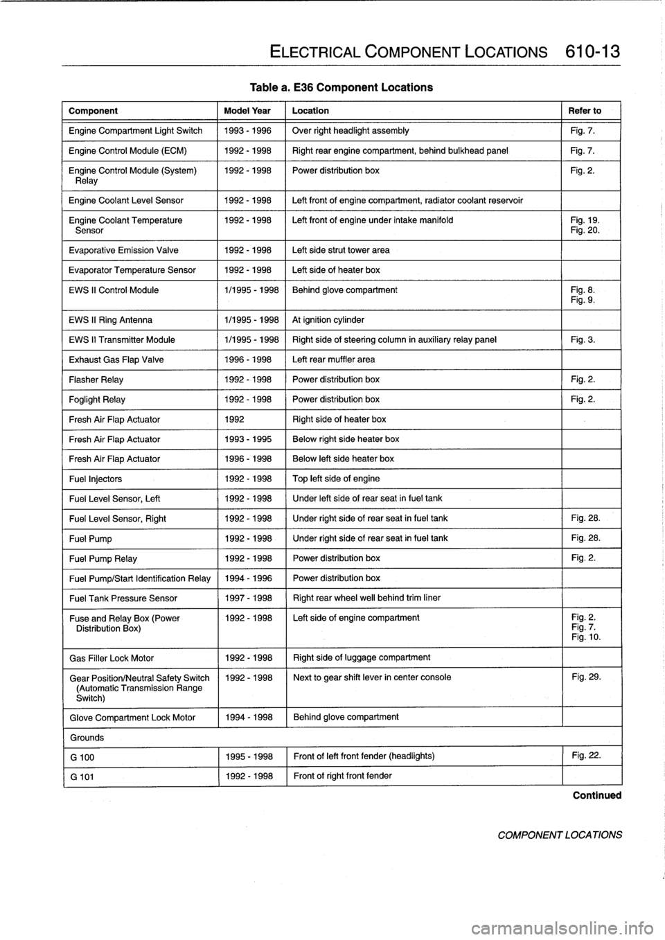
Tablea
.
E36
Component
Locations
Component
Model
Year
Location
Refer
to
Engine
Compartment
Light
Switch
1993-1996
Over
right
headlight
assembly
Fig
.
7
.
Engine
Control
Module
(ECM)
1992-1998
Right
rear
enginecompartment,
behind
bulkhead
panel
Fig
.
7
.
Engine
Control
Module
(System)
1992-1998
I
Power
distribution
box
Fig
.
2
.
Relay
Engine
Coolant
Leve¡
Sensor
1
1992-1998
1
Left
front
of
enginecompartment,
radiator
coolant
reservoir
Engine
Coolant
Temperature
1992-1998
I
Left
front
of
engine
under
intake
manifold
I
Fig
.
19
.
Sensor
Fig
.
20
.
Evaporative
Emission
Valve
1992-1998
Left
side
strut
Power
area
Evaporator
Temperature
Sensor
1992-1998
Left
side
of
heater
box
EWS
II
Control
Module
1/1995
-
1998
Behind
glove
compartment
Fig
.
8
.
Fig
.
9
.
EWS
II
Ring
Antenna
1
1/1995
-
1998
1
At
ignition
cylinder
EWS
II
Transmitter
Module
1/1995
-
1998
Right
side
of
steering
column
in
auxiliaryrelay
panel
Fig
.
3
.
Exhaust
Gas
Flap
Valve
1996-1998
Left
rear
muffler
area
Flasher
Relay
1992-1998
Power
distribution
box
Fig
.
2
.
Foglight
Relay
1
1992-1998
1
Power
distribution
box
1
Fig
.
2
.
Fresh
Air
FlapActuator
1
1992
1
Right
side
of
heater
box
Fresh
Air
FlapActuator
1
1993-1995
1
Below
right
side
heater
box
Fresh
Air
FlapActuator
1
1996-1998
Below
left
side
heater
box
Fuel
Injectors
1992
-
1998
Top
left
side
of
engine
Fuel
Leve¡
Sensor,
Left
1
1992-1998
/
Under
left
side
of
rear
seat
infuel
tank
Fuel
Leve¡
Sensor,
Right
1
1992-1998
1
Under
right
side
of
rear
seat
in
fuel
tank
1
Fig
.
28
.
Fuel
Pump
1
1992-1998
1
Under
right
side
of
rear
seat
in
fuel
tank
1
Fig
.
28
.
Fuel
Pump
Relay
1
1992-1998
1
Power
distribution
box
1
Fig
.
2
.
Fuel
Pump/Start
Identification
Relay
1994
-
1996
Power
distribution
box
Fuel
Tank
Pressure
Sensor
1
1997-1998
1
Right
rear
wheel
well
behind
trim
liner
ELECTRICAL
COMPONENT
LOCATIONS
610-13
Fuse
andRelay
x(Power
11992-1998
I
Left
side
of
engine
compartment
I
Fig
.
2
.
Distribution
Box
Fig
.
7
Fig
.
10
.
Gas
Filler
LockMotor
1992-1998
Right
side
of
luggage
compartment
Gear
Position/Neutral
Safety
Switch
1992-1998
Next
to
gear
shift
lever
in
center
console
Fig
.
29
.
(Automatic
Transmission
Range
Switch)
Glove
Compartment
Lock
Motor
1994-1998
Behind
glove
compartment
Grounds
G
100
1995-1998
Front
of
left
front
fender
(headlights)
Fig
.
22
.
G
101
1992-1998
Front
of
right
front
fender
Continued
COMPONENT
LOCATIONS
Page 402 of 759
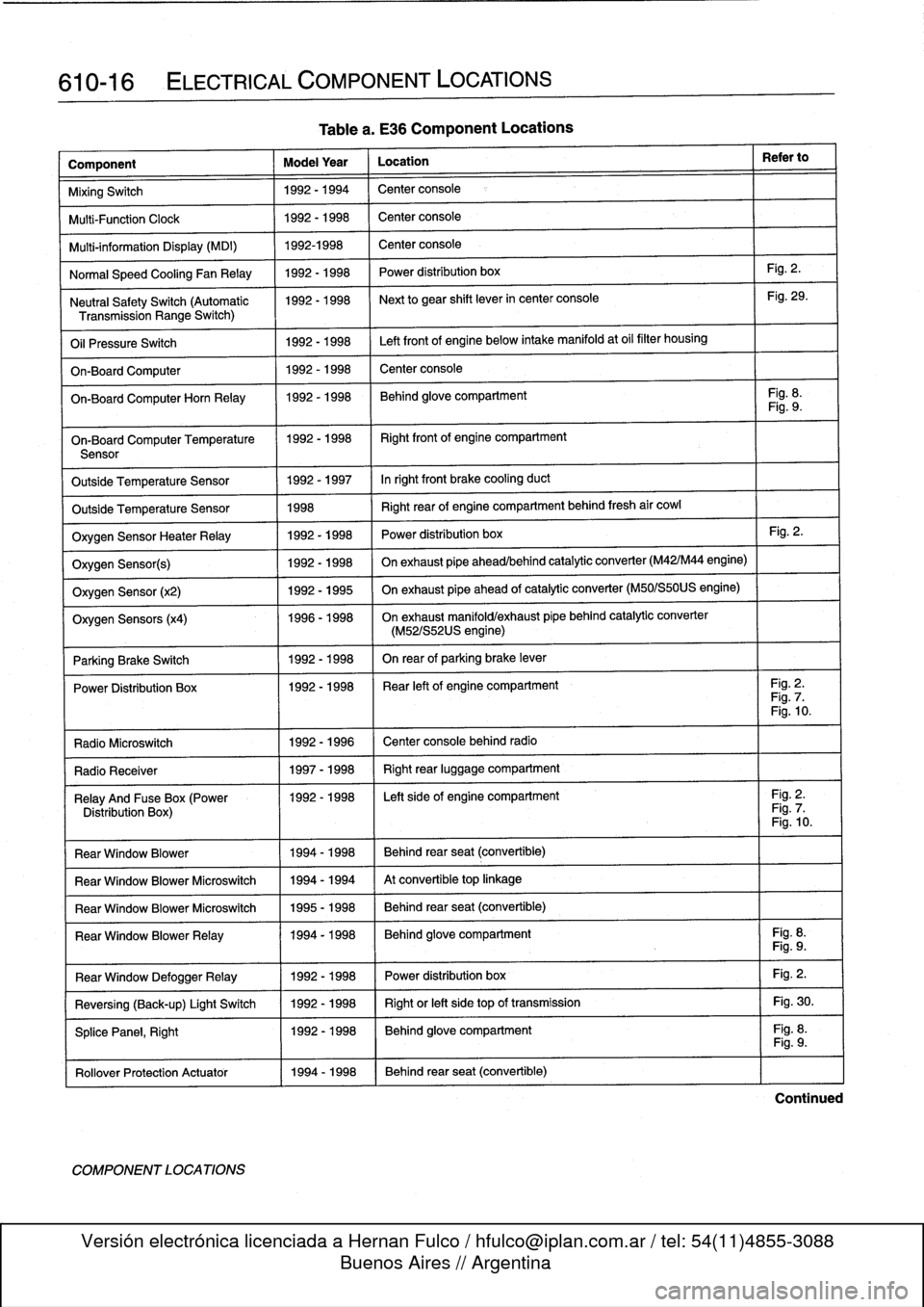
610-16
ELECTRICAL
COMPONENT
LOCATIONS
Component
Model
Year
Location
Refer
to
MixingSwitch
1992-1994
Center
console
Multi-Function
Clock
1992-1998
Center
console
Multi-information
Display
(MDI)
1992-1998
Center
console
Normal
Speed
Cooling
Fan
Relay
1992-1998
Power
distribution
box
Fig
.
2
.
Neutral
SafetySwitch
(Automatic
1992-1998
Next
to
gear
shift
lever
in
center
console
Fig
.
29
.
Transmission
Range
Switch)
Oil
Pressure
Switch
1992-1998
Left
front
of
engine
below
intake
manifold
at
oil
filter
housing
On-Board
Computer
1992-1998
Center
console
On-BoardComputerHorn
Relay
1992-1998
Behind
glove
compartment
Fig
.
8
.
Fig
.
9
.
On-Board
Computer
Temperature
11992-1998
I
Right
front
of
engine
compartment
Sensor
Outside
Temperature
Sensor
1992-1997
Inright
front
brake
cooling
duct
Outside
Temperature
Sensor
1998
Right
rear
of
engine
compartment
behind
fresh
air
cowl
Oxygen
Sensor
HeaterRelay
1992-1998
Power
distribution
box
Fig
.
2
.
Oxygen
Sensor(s)
1992-1998
On
exhaust
pipe
ahead/behind
catalytic
converter
(M42/M44
engine)
Oxygen
Sensor
(x2)
1992-1995
On
exhaust
pipe
ahead
of
catalytic
converter
(M50/S50US
engine)
Oxygen
Sensors
(x4)
1996-1998
On
exhaust
manifold/exhaust
pípe
behind
catalytic
converter
(M52/S52US
engine)
Parking
Brake
Switch
1
1992-1998
I
On
rear
of
parking
brake
lever
Power
Distribution
Box
11992-1998
I
Rear
left
of
engine
compartment
I
Fig
.
2
.
Fig
.
7
.
Fig
.
10
.
Radio
Microswitch
1992
-
1996
Center
console
behind
radio
Radio
Receíver
1
1997-1998
1
Right
rear
luggage
compartment
Relay
And
Fuse
Box
(Power
1992-1998
I
Left
side
of
engine
compartment
I
Fig
.
2
.
Distribution
Box)
Fig
.
7
.
Fig
.
10
.
Rear
Window
Blower
1994-1998
Behind
rear
seat
(convertible)
Rear
Window
Blower
Microswitch
1994-1994
At
convertible
top
linkage
Rear
Window
Blower
Microswitch
1995-1998
Behind
rear
seat
(convertible)
Rear
Window
BlowerRelay
11994-1998
Behind
glove
compartment
Fig
.
8
.
Fig
.
9
.
Fig
.
2
.
Fig
.
30
.
Fig
.
8
.
Rear
Window
DefoggerRelay
Reversing
(Back-up)
Light
Switch
SplicePanel,
Right
Rollover
Protection
Actuator
11994-1998
COMPONENT
LOCATIONS
Table
a
.
E36
Component
Locations
1992-1998
1992-1998
1992-1998
Power
distribution
box
Right
or
left
side
top
of
transmission
Behind
glove
compartment
Behind
rear
seat
(convertible)
Fig
.
9
.
Continued