Rear window BMW 325i 1992 E36 Workshop Manual
[x] Cancel search | Manufacturer: BMW, Model Year: 1992, Model line: 325i, Model: BMW 325i 1992 E36Pages: 759
Page 20 of 759
010-12
FUNDAMENTALSFOR
THE
DO-IT
YOURSELF
OWNER
Jump
Starting
Car
Cars
with
discharged
or
dead
batteries
can
be
jump-started
using
the
good
battery
from
another
car
.
When
jump-starting
the
engine,
always
note
the
following
warnings
.
WARNING
-
"
Battery
acid
(electrolyte)
can
cause
severe
burns,
and
will
damage
the
car
and
clothing
.
lf
electrolyte
is
spilled,
wash
the
surface
with
large
quantities
of
water
.
lfit
gets
finto
eyes,
flush
them
with
water
for
severa¡
minutes
and
cal¡
a
doctor
.
"
Batteries
produce
explosive
and
noxious
gas-
ses
.
Keep
sparks
and
flames
away
.
Do
not
smoke
near
batteries
.
"
Do
not
jump-start
the
engine
if
you
suspect
that
the
battery
is
frozen
.
Trapped
gas
may
explode
.
Allow
the
battery
to
thaw
first
.
"
Do
not
quick-charge
the
battery
(for
boost
start-
ing)for
longer
than
one
minute,
and
donot
ex-
ceed
15
volts
at
the
battery
with
the
boosting
cables
attached
.
Wait
at
least
one
minutebefore
boosting
the
battery
a
second
time
.
"
Some
electrical
system
'comfort"
features
may
not
function
correctly
once
battery
power
is
restored
.
For
example,
the
front
window
one-touch-up
func-
tion
may
be
disabled
.
Some
electrical
systems
will
need
to
be
reinitialized
Consult
the
appropriate
re-
pairgroup
formore
specific
information
.
1
.
Place
cars
close
together,
but
do
not
allow
them
to'touch
each
other
.
Turn
off
the
engine
of
thecar
with
the
good
battery
.
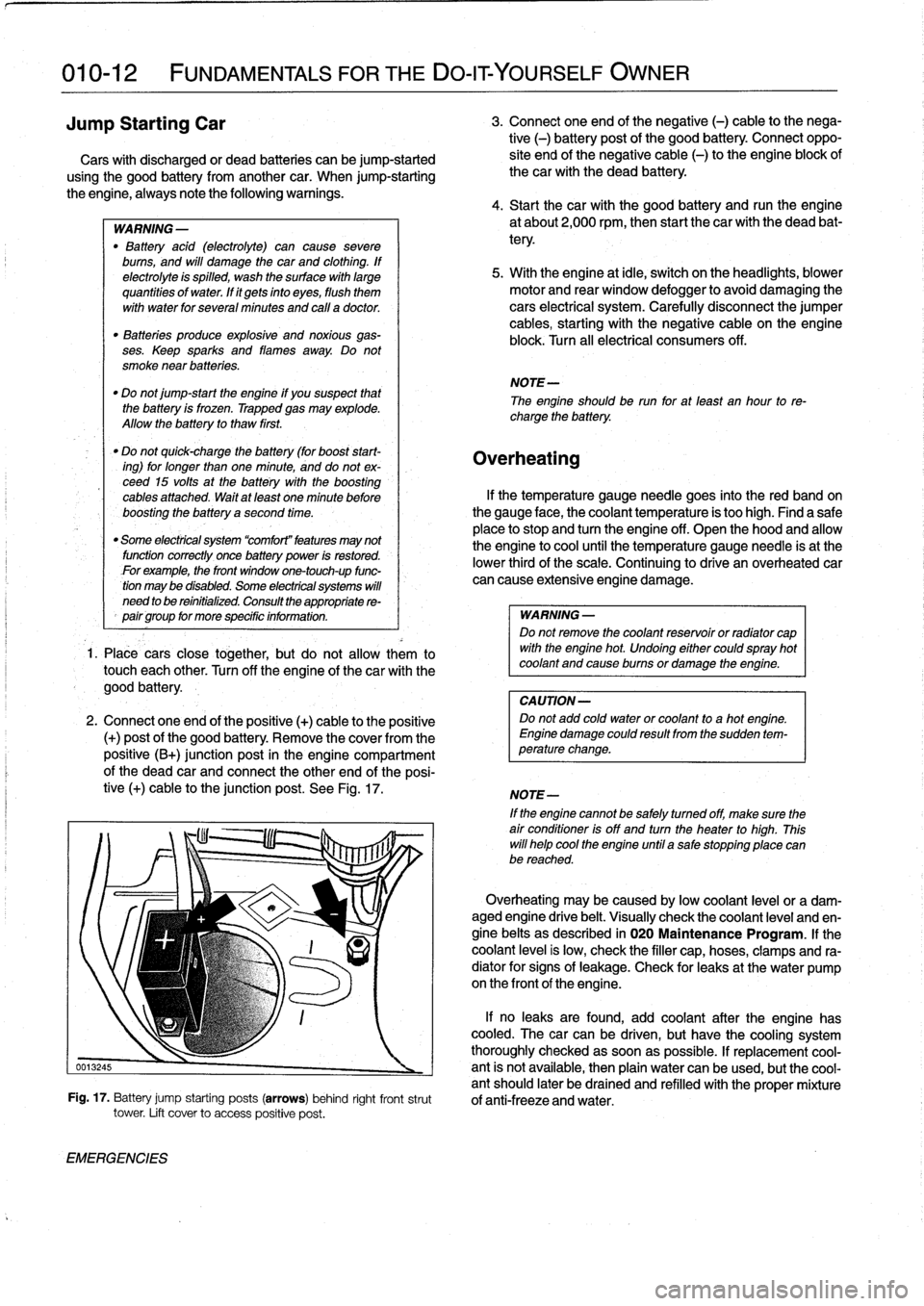
2
.
Connect
oneend
of
the
positive
(+)
cable
to
the
positive
(+)
post
of
the
good
battery
.
Remove
the
coverfromthe
positive
(B+)
junction
post
in
the
engine
compartment
of
the
dead
car
and
connect
the
other
end
of
the
posi-
tive
(+)
cable
to
the
junction
post
.
See
Fig
.
17
.
EMERGENCIES
3
.
Connect
one
end
of
the
negative
(-)
cable
to
the
nega-
tive
(-)
battery
post
of
the
good
battery
.
Connect
oppo-
site
end
of
the
negative
cable
(-)
to
the
engine
block
of
thecar
with
the
dead
battery
.
4
.
Start
thecar
with
the
good
battery
and
runthe
engine
at
about2,000
rpm,
then
start
the
car
with
the
dead
bat-
tery
.
5
.
With
the
engine
at
¡dle,
switch
on
the
headlights,
blower
motor
and
rear
window
defogger
to
avoid
damaging
the
cars
electrical
system
.
Carefully
disconnect
the
jumper
cables,
starting
with
the
negative
cable
on
the
engine
block
.
Turn
all
electrical
consumers
off
.
NOTE-
The
engineshould
be
run
for
at
least
an
hour
to
re-
charge
the
battery
.
Overheating
lf
the
temperature
gauge
needle
goes
into
the
red
band
on
the
gauge
face,
the
coolant
temperature
is
too
high
.
Find
a
safe
place
to
stop
and
turn
the
engine
off
.
Open
the
hood
and
allow
the
engine
to
cool
until
the
temperature
gauge
needle
is
at
the
lower
thirdof
the
scale
.
Continuing
to
drive
an
overheated
car
can
cause
extensive
engine
damage
.
WARNING
-
Do
not
remove
the
coolant
reservoir
or
radíator
cap
with
the
engine
hot
.
Undoing
either
couldspray
hot
coolant
and
cause
burns
or
damage
the
engine
.
CAUTION-
Do
not
add
cold
water
or
coolant
to
a
hot
engine
.
Engine
damage
could
result
from
the
sudden
tem-
perature
change
.
NOTE-
If
the
enginecannot
be
safely
tumed
off,
make
sure
the
air
condifioner
isoff
and
turn
the
heater
to
high
.
This
will
helo
cool
the
engine
until
a
salestopping
place
canbe
reached
.
Overheating
may
be
caused
bylow
coolant
leve¡
or
a
dam-aged
engine
drive
belt
.
Visually
check
the
coolant
leve¡
and
en-
gine
belts
as
described
in
020
Maintenance
Program
.
lf
the
coolant
leve¡
is
low,
check
the
filler
cap,hoses,
clamps
and
ra-
diator
for
signs
of
leakage
.
Check
for
leaks
at
the
water
pump
on
the
frontof
theengine
.
lf
no
leaks
are
found,
add
coolant
after
the
engine
has
cooled
.
The
carcan
be
driven,
but
have
the
cooling
system
thoroughly
checked
assoonas
possible
.
lf
replacement
cool
0013245
-
ant
is
not
available,
then
plain
water
canbe
used,
butthe
cool-
antshould
later
be
drained
and
refilled
with
theproper
mixture
Fig
.
17
.
Battery
jump
starting
posts
(arrows)
behind
right
frontstrut
of
anti-freeze
and
water
.
tower
.
Lift
cover
to
access
positive
post
.
Page 141 of 759
2
.
Remove
cooling
duct
or
terminal
cover
from
rear
of
al-
2
.
Remove
air
cleaner
upper
section
with
mass
air
flow
ternator
.
sensor
.
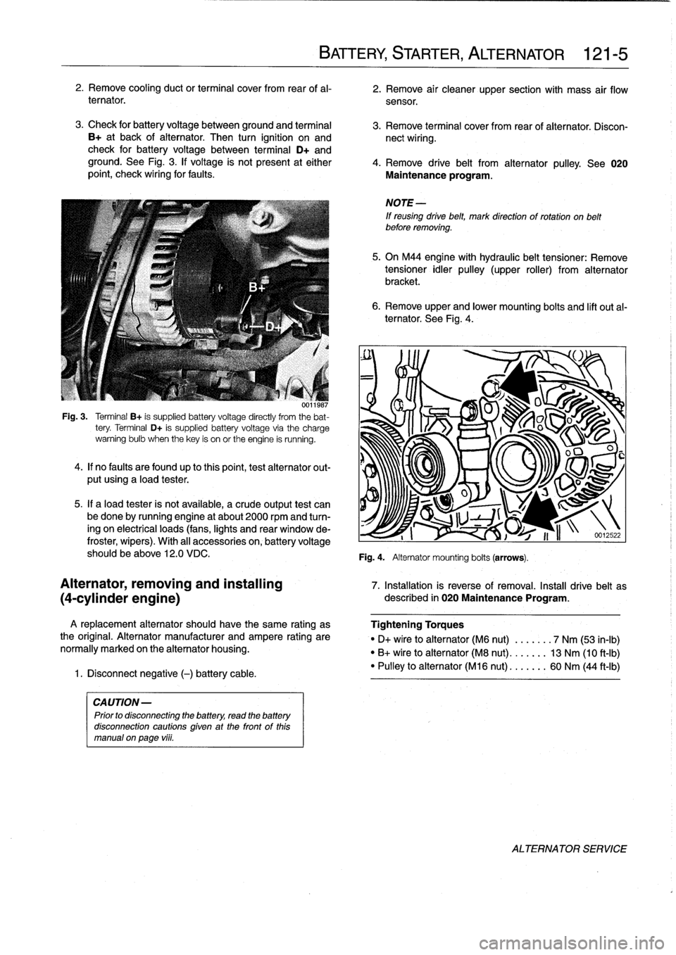
3
.
Check
for
battery
voltage
between
ground
and
terminal
3
.
Remove
terminal
cover
from
rear
of
alternator
.
Discon
B+
at
back
of
alternator
.
Then
turn
ignition
on
and
nect
wiring
.
check
for
battery
voltage
between
terminal
D+
and
ground
.
See
Fig
.
3
.
lf
voltage
is
not
present
at
either
4
.
Remove
drive
belt
from
alternator
pulley
.
See
020
point,
check
wiring
for
faults
.
Maintenance
program
.
001
¡987
Fig
.
3
.
Terminal
B+
is
supplied
battery
voltage
directly
from
the
bat-
tery
.
Terminal
D+
is
supplied
battery
voltage
via
the
charge
warning
bulb
when
thekey
is
on
or
the
engine
is
running
.
4
.
lf
no
faults
are
foundup
to
thispoint,test
alternator
out-
put
using
a
load
tester
.
5
.
If
a
load
tester
is
not
available,
a
crude
output
test
can
be
done
by
running
engine
at
about
2000
rpmand
turn-
ing
on
electrical
loads
(fans,
lights
and
rear
window
de-
froster,
wipers)
.
With
al¡
accessories
on,
battery
voltage
should
be
above
12
.0
VDC
.
A
replacement
alternator
should
have
the
same
rating
as
the
original
.
Alternator
manufacturer
and
ampere
rating
are
normally
marked
on
the
alternator
housing
.
1
.
Disconnect
negative
(-)
battery
cable
.
CAUTION-
Prior
to
disconnecting
the
battery,
read
the
battery
disconnection
cautions
given
at
the
front
of
this
manual
on
page
vi¡¡
.
BATTERY,
STARTER,
ALTERNATOR
121-
5
6
.
Remove
upper
and
lower
mounting
bolts
and
lift
out
al-
ternator
.
See
Fig
.
4
.
NOTE
-
If
reusing
drive
belt,
mark
direction
of
rotation
on
belt
before
removing
.
5
.
On
M44
engine
with
hydraulic
belt
tensioner
:
Remove
tensioner
idler
pulley
(upper
roller)
from
alternator
bracket
.
Fig
.
4
.
Alternator
mounting
bolts
(arrows)
.
O
u
J
S
v~~
U
I
1
i
n
-12
.22
Alternator,
removing
and
installing
7
.
Installation
is
reverse
of
removal
.
Install
drive
belt
as
(4-cylinder
engine)
described
in
020
Maintenance
Program
.
Tightening
Torques
"
D+
vire
to
alternator
(M6
nut)
.
...
.
.
.
7
Nm
(53
in-lb)
"
B+
wire
to
alternator
(M8
nut)
..
.
.
.
.
.
13
Nm
(10
ft-Ib)
"
Pulley
to
alternator
(M16
nut)
...
..
..
60
Nm
(44
ft-Ib)
ALTERNATOR
SERVICE
Page 304 of 759
400-2
BODY-GENERAL
4-door
Sedan
Coupe
-
saas3
.7""
351
/
37
.3
O
I
x
`-193
267
o
oa
'3281
model
"M3
model
Convertible
BODYASSEMBLY
55
ass
.e
iss
""
-
66
.9
-
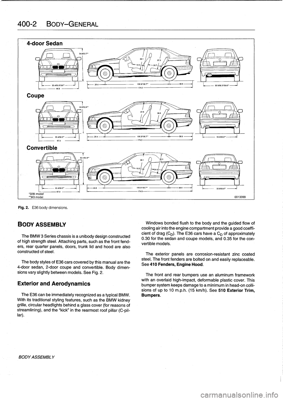
Fig
.
2
.
E36
body
dimensíons
.
BODY
ASSEMBLY
29
.4
29
4
The
BMW
3
Series
chassis
is
a
unibodydesign
constructed
ofhigh
strength
steel
.
Attaching
parts,
suchas
the
front
fend-
ers,
rear
quarter
panels,
doors,
trunk
lid
and
hood
are
also
constructed
of
steel
.
706
.31108
.7"
I
38
.5
174
.5
174
.5
O
oo
196
.3/106
.7'
"
35_5
1.
.
55
.9,566
".
106
.3/196
.7""
i.
358
-1745-
55
9/56
3'/56
6"
-
J
0013099
Windows
bonded
flush
to
the
body
and
the
guided
flow
of
cooling
air
into
the
engine
compartment
provide
a
good
coeffi-
cient
of
drag(CD)
.
TheE36
cars
have
a
CD
of
approximately
0
.30for
the
sedan
and
coupe
models,
and
0
.35
for
the
con-
vertible
models
:
The
exterior
panels
are
corrosion-resistant
zinc
coated
steel
.
The
front
fenders
are
bolted
on
and
easily
replaceabie
.
The
body
styles
of
E36
cars
coveredby
this
manual
arethe
See410
Fenders,
Engine
Hood
.
4-door
sedan,
2-door
coupe
and
convertible
.
Body
dimen-
sions
vary
slightly
betweenmodels
.
See
Fig
.
2
.
The
front
and
rear
bumpers
use
an
aluminum
framework
with
an
overlaid
high-impact,
deformable
plastic
cover
.
This
Exterior
and
Aerodynamics
bumper
system
keeps
damage
to
a
minimum
in
head-on
colli-
sions
of
up
to
10
m
.p
.h
.
(15
km/h)
.
See
510
Exterior
Trim,
TheE36
can
be
immediatelyrecognized
asa
typical
BMW
.
Bumpers
.
With
its
traditionalstyling
features,
suchas
the
BMW
kidney
grille,
circular
headlights
behind
a
glass
cover
(for
reasons
of
streamliníng),
and
the
"kick"
in
the
rearmost
roof
pillar
(C-pil-
lar)
.
Page 305 of 759
TheE36
convertible
is
an
all-season
vehicle
with
a
high
lev-
e¡offunctionality,
excellent
interior
comfort,
and
acoustic
re-
finement
.
Interior
materials
and
colors,
the
soft
top
and
the
light-alloy
wheelshave
been
carefully
matched
.
Various
versions
of
manual
and
automatic
soft
tops
have
been
used,
with
the
fully
automatic
convertible
roof
being
in-
stalled
beginning
in
the
1997
model
year
.
A
hard-top
in
body
color
with
heated
rear
window
is
avail-
ableas
an
option
for
the
cold
season
.
BODY-GENERAL
400-
3
Coupe
Models
The
convertible
body
structure
includes
many
passive
safe-
ty
refinements
over
its
fixed-top
counterparts
.
Some
of
the
en-
TheE36
coupe
is
similar
to
the4-door
sedan,
but
has
a
hancements
include
:
more
stretched
and
sleeker
appearance
.
Thus,
with
the
same
wheelbase
and
identicallength,
it
looks
different
but
still
famil-
"
More
rígíd
underbody
.
iar
.
"
Transverse
seat
members
.
"
Reinforced
windshield
frame
with
bonded
windshield,
The
2-door
variant
differs
from
the
4-door
sedan
by
a
3
.12
and
tubular
door
reinforcements
.
inch
(8
cm)
longer
front
end,
a
flatter
hood
line
with
air
slits,
"
Rollover
protection
system,
which
is
tripped
into
position
and
a
roof
almost
1
.2
inches
(3
cm)
shorter
.
Additional
differ-
in
a
fraction
of
second
.
This
is
available
as
optional
ences
include
wider
doors
with
frameless
Windows,
glass-
equipment
(standard
on
the
1998
328iC)
and
may
be
fit-
covered
door-posts
(B-pillars)
and
a
shorter
and
lower
lug-
ted
to
earlier
convertible
models
.
With
this
feature,
two
gage
compartment
lid
.
bars
fully
independent
of
each
other
come
up
behind
each
rear-seat
backrest
when
the
vehicle
is
in
danger
of
Convertible
Models
turning
over
.
A
convertible
body
normally
flexes
and
vibrates,
transfer-
ring
oscillations
to
the
luggage
compartment
.
In
the
E36
con-
vertible,
BMW
utilizes
a
special
battery
in
the
luggage
compartment,
in
conjunction
with
a
unique
battery
tray,
asa
vibration
dampening
system
to
counteract
thisoscillation
.
CAUTION
-
The
E36
convertible
requires
a
specialbattery
which
is
designed
for
constant
vibration
.
Information
for
the
convertible
top
and
its
related
mecha-
nisms
can
be
found
541
Convertible
Top
.
BODYASSEMBLY
Page 315 of 759
GENERAL
This
repair
group
covers
front
and
rear
door
repair
informa-
tion,
including
removal
and
installationof
the
interior
doorpan-
els
.
DOORS
WARNING
-
Late
M3
moddis
havealuminum
doors
.
Use
extra
care
in
handling
aluminum
parts
in
order
to
avoid
damage
from
gouging
or
corrosión
.
NOTE-
"
For
information
on
the
power
door
windows
and
door
glass
replacement,
sea512Door
Windows
.
"
Forinformation
on
the
power
door
locking
system,
see
515
Central
Locking
and
Anti-Theft
.
WARNING
-
Some
1997
and
all
1998
cars
are
fitted
with
side-im-
pact
airbags
in
the
front
doors
.
When
servicing
doors
on
cars
with
front
side-impact
airbags,
always
dis-
connect
the
negative
(-)
battery
terminal
.
See
721
Airbag
System
(SRS)
for
cautions
and
procedures
relating
to
the
airbag
system
.
Front
orrear
door,
removing
and
installing
1
.
If
workingon
front
door
with
side-impact
airbag,
discon-
nect
negative
(-)
battery
cable
.
CAUTION
-
Prior
to
disconnectiog
the
battery,
read
the
battery
disconnection
cautions
given
at
the
front
of
this
manual
on
page
vüi
.
2
.
Unbolt
main
harness
connector
at
door
pillar
and
sep-
arate
connector
.
See
Fig
.
1
.
411
Doors
GENERAL
.............
.
.
.
.
.
.
.
.
.
.
.
.
.
..
411-1
DOOR
PANELS
.
.
.
.
.
.
.
...
.
.
.
.
.
.
.
.
.
...
.
.
411-4
Front
door
trim
panel,
removing
and
installing
.411-4
DOORS
..
.
.
.
.
.
.
.
.
.
...
.
.......
.
....
.
.
.
411-1
Rear
door
trim
panel,
removing
and
installing
.411-5
Front
or
reardoor,
removing
and
installing
..
.
411-1
Rear
side
trim
panel,
removing
and
installing
Door
check,
replacing
.
.
.
.
.
.
.
.
.
.
.
.
.......
411-3
(coupemodel)
.
.
.
.
.
.
....
.
.............
411-6
Door
Adjustment
.......
.
.
.
.
.
.
.
.
.
.
.
.....
411-3
Rear
side
trim
panel,
removing
and
installing
(convertible
models)
.
...
.
.
.
.
.
.
.
.
.
.
.
...
.
411-6
DOORS
411-1
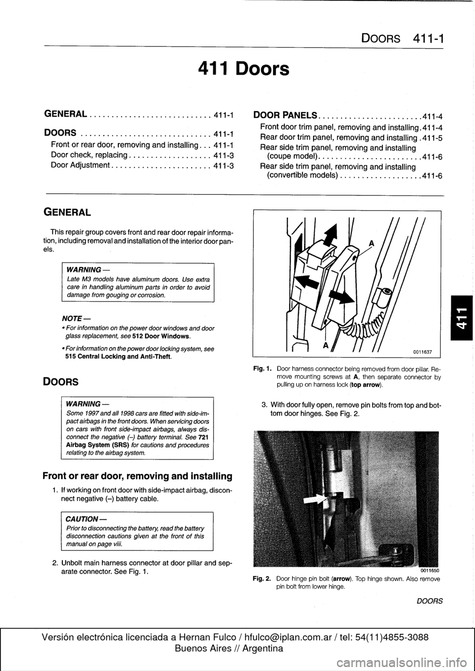
Fig
.
1
.
Door
harness
connector
being
removed
fromdoor
pillar
.
Re-
move
mountingscrews
atA,
then
separate
connector
by
pulling
upon
harness
lock(top
arrow)
.
3
.
Withdoor
fully
open,
remove
pin
bolts
from
top
and
bot-
tom
door
hinges
.
See
Fig
.
2
.
0011650
Fig
.
2
.
Door
hinge
pin
bolt
(arrow)
.
Top
hinge
shown
.
Also
remove
pin
bolt
from
lowerhinge
.
DOORS
Page 316 of 759
411-2
DOORS
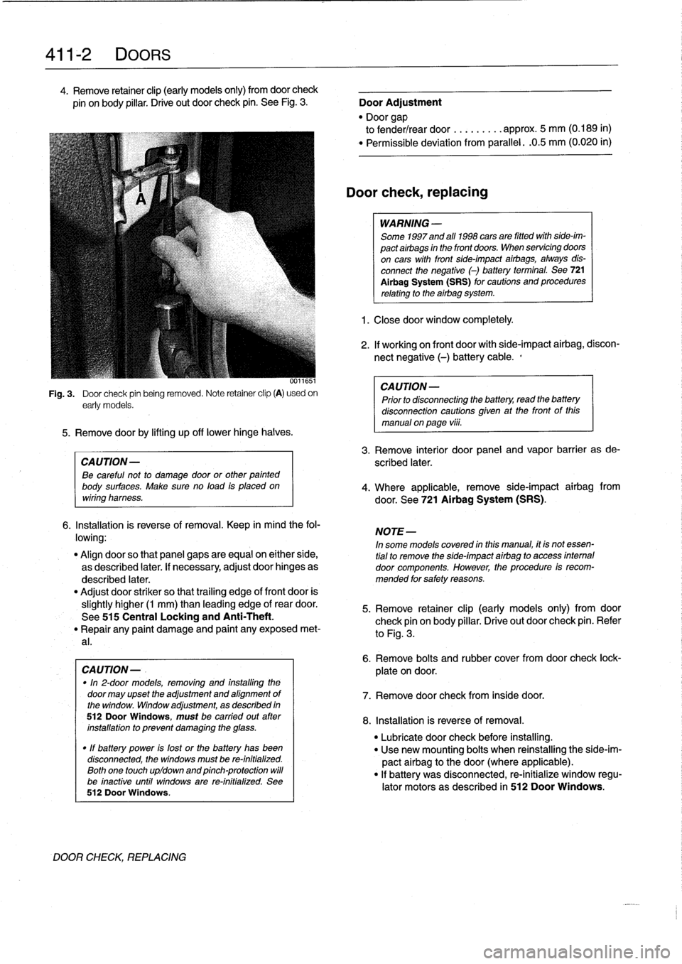
4
.
Remove
retainer
clip
(early
models
only)
from
doorcheck
pin
onbody
pillar
.
Drive
out
door
check
pin
.
See
Fig
.
3
.
Door
Adjustment
"
Door
gap
to
fender/rear
door
.........
approx
.
5
mm
(0
.189
in)
"
Permíssible
deviation
from
parallel
.
.0
.5
mm
(0
.020
in)
0011651
Fig
.
3
.
Door
check
pin
being
removed
.
Note
retainer
clip
(A)
usedon
early
models
.
5
.
Remove
doorby
lifting
up
off
lowerhinge
halves
.
CAUTION-
Be
careful
not
to
damage
door
or
other
painted
body
surfaces
.
Make
sure
no
load
is
placedon
wiring
harness
.
6
.
Installation
is
reverse
of
removal
.
Keep
in
mind
the
fol-
lowing
:
"
Align
doorso
that
panel
gaps
are
equal
on
either
side,
as
described
later
.
If
necessary,
adjust
door
hinges
as
described
later
.
"
Adjust
door
striker
so
that
trailing
edge
of
front
door
is
slightly
higher
(1
mm)
than
leading
edge
of
rear
door
.
See
515
Central
Locking
and
Anti-Theft
.
"
Repair
any
paint
damage
and
paínt
any
exposed
met-
al
.
CAUTION-
.
"In
2-door
models,
removing
and
installing
the
door
may
upset
the
adjustment
and
alignment
of
the
window
.
Window
adjustment,
as
described
in
512DoorWindows,
must
be
carried
out
ater
installation
to
prevent
damaging
the
glass
.
"
If
battery
power
is
lost
or
the
battery
has
been
disconnected,
the
windows
must
be
re-initialized
.
Both
one
touch
upldown
and
pinch-protection
will
be
inactive
until
windows
are
re-initialized
.
See
512
Door
Windows
.
DOOR
CHECK,
REPLACING
Door
check,replacing
WARNING
-
Some
1997
and
all
1998
cars
are
fitted
with
side-im-
pact
airbags
in
the
front
doors
.
When
servicing
doors
on
cars
with
front
side-impact
airbags,
always
dis-
connect
the
negative
(-)
battery
terminal
.
See
721
Al
rbag
System
(SRS)
for
cautions
and
procedures
relating
to
the
airbag
system
.
1
.
Closedoor
window
completely
.
2
.
If
working
on
front
door
with
side-impact
airbag,
discon-
nect
negative
(-)
battery
cable
.,
CAUTION-
Prior
to
disconnectiog
the
battery,
read
the
battery
disconnection
cautions
gíven
at
the
front
of
this
manual
on
page
viii
.
3
.
Remove
interior
door
panel
and
vapor
barrier
as
de-
scribed
later
.
4
.
Where
applicable,
remove
side-impact
airbag
from
door
.
See
721
Airbag
System
(SRS)
.
NOTE-
In
some
models
covered
inthis
manual,
ít
is
not
essen-
tial
to
remove
the
side-ímpact
airbag
to
access
internal
door
components
.
However,
the
procedure
is
recom-
mended
for
safety
reasons
.
5
.
Remove
retainer
clip
(early
models
only)
from
door
check
pin
on
body
pillar
.
Drive
out
door
check
pin
.
Refer
to
Fig
.
3
.
6
.
Remove
bolts
and
rubber
cover
fromdoor
check
lock-
plate
ondoor
.
7
.
Remove
door
check
from
inside
door
.
8
.
Installation
is
reverse
of
removal
.
"
Lubricate
door
check
before
installing
.
"
Use
new
mounting
bolts
when
reinstalling
the
side-im-
pact
airbag
to
thedoor(where
applicable)
.
"
If
battery
was
disconnected,
re-initialize
window
regu-
lator
motors
as
described
in
512
Door
Windows
.
Page 318 of 759
411-
4
DOORS
6
.
Disconnect
radio
speaker
harness
connector
.
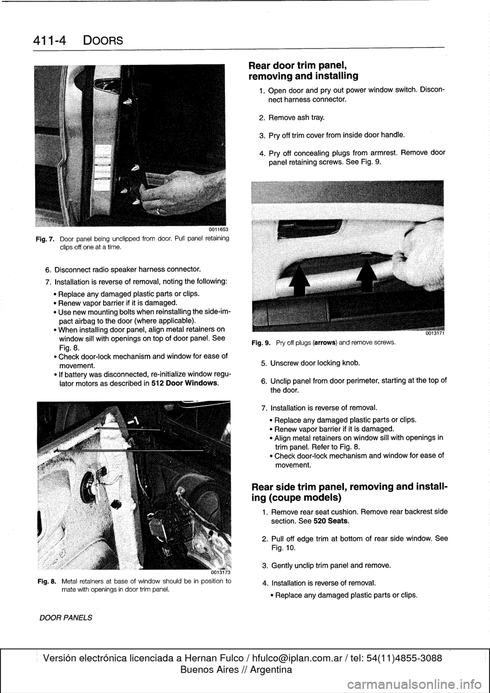
Fig
.
7
.
Door
panel
being
unclipped
from
door
.
Pull
panel
retaining
clips
off
one
at
a
time
.
7
.
Installation
is
reverse
of
removal,
noting
the
following
:
"
Replace
any
damaged
plastic
parts
orclips
.
"
Renew
vapor
barrier
ifit
is
damaged
.
"
Use
new
mounting
bolts
when
reinstalling
the
side-im-
pactairbag
to
the
door
(where
applicable)
.
"
When
installing
door
panel,
align
metal
retainers
on
window
sill
with
openingsontop
of
door
panel
.
See
Fig
.
8
.
"
Check
door-lock
mechanism
and
window
for
ease
of
movement
.
"
If
battery
was
disconnected,
re-initialize
window
regu-
lator
motors
as
described
in
512
Door
Windows
.
373
Fig
.
8
.
Metal
retainers
at
base
of
window
should
be
in
position
to
mate
with
openings
in
door
trim
panel
.
DOOR
PANELS
Reardoor
trimpanel,
removing
and
installing
1
.
Open
door
and
pry
out
power
window
switch
.
Discon-
nect
harness
connector
.
2
.
Remove
ash
tray
.
3
.
Pry
off
trim
cover
from
inside
door
handle
.
4
.
Pry
off
concealing
plugs
from
armrest
.
Remove
door
panel
retaining
screws
.
See
Fig
.
9
.
Fig
.
9
.
Pry
off
plugs
(arrows)
andremove
screws
.
5
.
Unscrew
door
locking
knob
.
6
.
Unclip
panel
from
door
perimeter,
starting
at
thetop
of
the
door
.
7
.
Installation
is
reverse
of
removal
.
"
Replace
any
damaged
plastic
parts
or
clips
.
"
Renew
vapor
barrier
ifit
is
damaged
.
"
Align
metal
retainers
on
window
sill
with
openings
in
trim
panel
.
Refer
to
Fig
.
8
.
"
Check
door-lock
mechanism
and
window
for
ease
of
movement
.
Rear
side
trim
panel,
removing
and
install-
ing
(coupe
models)
1
.
Remove
rear
seat
cushion
.
Remove
rear
backrest
side
section
.
See
520
Seats
.
2
.
Pull
off
edge
trimat
bottom
of
rear
side
window
.
See
Fig
.
10
.
3
.
Gently
unclip
trim
panel
andremove
.
4
.
Installation
is
reverse
of
removal
.
"
Replace
any
damaged
plastic
parts
or
clips
.
Page 319 of 759
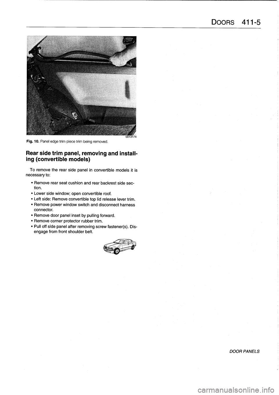
Fig
.
10
.
Panel
edge
trim
piece
trim
being
removed
.
Rear
side
trimpanel,
removing
and
install-
ing
(convertible
models)
To
remove
the
rearside
panel
in
convertible
models
it
is
necessary
to
:
"
Remove
rear
seat
cushion
and
rear
backrest
side
sec-
tion
.
"
Lower
side
window
;
open
convertible
roof
.
"
Leftside
:
Remove
convertible
top
lid
release
lever
trim
.
"
Remove
power
window
switch
and
disconnect
harness
connector
.
"
Remove
door
panel
inset
by
pulling
forward
.
"
Remove
corner
protector
rubber
trim
.
"
Pull
off
side
panel
after
removing
screw
fastener(s)
.
Dis-
engage
from
front
shoulder
belt
.
Page 331 of 759
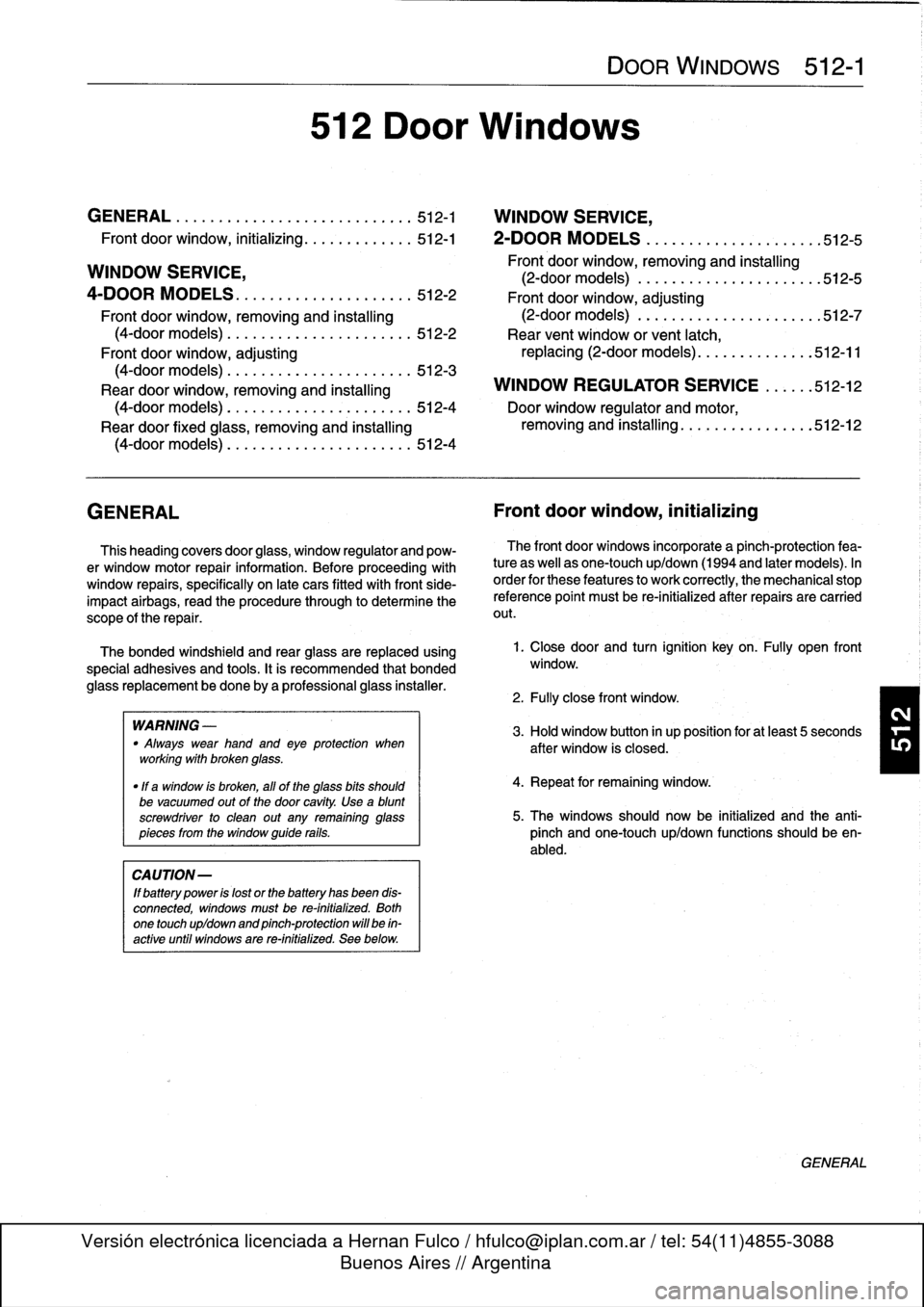
GENERAL
......
.
........
.
.
.
.
.
.
.
...
.
.
.
512-1
WINDOW
SERVICE,
Front
door
window,
initializing
..
.
.........
.
512-1
2-DOOR
MODELS
.
...
.
......
.
........
.512-5
WINDOW
SERVICE,
Front
door
window,
removing
and
installing
(2-door
models)
.
.
...
.
...............
.
512-5
4-DOOR
MODELS
.
.
.
.
................
.
512-2
Front
door
window,
adjusting
Front
door
window,
removing
and
installing
(2-door
models)
.
.
.
.
.
.
.........
.
.
.
...
.512-7
(4-door
models)
.
.
.
.
.
...
.
.
.
.
.
.
.
.
.
.....
512-2
Rear
vent
window
or
vent
latch,
Front
door
window,
adjusting
replacing
(2-door
models)
....
.
.
.
.
.
.
.
...
512-11
(4-door
models)
.
.
.
.
.
...
.
...
.
.
.
.
.
.....
512-3
Rear
door
window,
removing
and
installing
WINDOW
REGULATOR
SERVICE
.
.
.
..
.512-12
(4-door
models)
.
.
.
.....
.
.
.
.
...
.
.
.....
512-4
Door
window
regulator
and
motor,
Rear
door
fixed
glass,
removing
and
installing
removing
and
installing
.
.
.
...
.
.
.
.
.
.
.
.
.
.
512-12
(4-door
models)
.
.
.
.
.
...
.
.
.
.
.
.
.
.
.
.....
512-4
GENERAL
Front
door
window,
initializing
This
heading
covers
door
glass,
window
regulator
and
pow-
er
window
motor
repair
information
.
Before
proceeding
with
window
repairs,
specifically
on
late
cars
fitted
with
front
side-
impact
airbags,
read
the
procedure
through
to
determine
the
scope
of
the
repair
.
The
bonded
windshield
and
rear
glass
are
replaced
using
special
adhesives
and
tools
.
It
is
recommended
that
bonded
glass
replacement
bedone
by
a
professional
glass
installer
.
WARNING
-
"
Always
wear
hand
and
eye
protection
when
workíng
with
broken
glass
.
"
ff
a
window
is
broken,
all
of
the
glass
bits
should
be
vacuumed
out
of
the
door
cavity
.
Use
a
blunt
screwdriver
to
clean
out
any
remaining
glass
pieces
from
the
window
guide
rails
.
CAUTION-
ff
battery
power
is
lost
or
the
battery
has
been
dis-
connected,
windows
mustbe
re-initialized
.
Both
one
touch
up/down
and
pinch-protection
will
be
in-
active
until
windows
are
re-initialized
.
Sea
below
.
512
Door
Windows
DOOR
WINDOWS
512-1
The
front
door
windows
incorporate
a
pinch-protection
fea-
ture
as
well
as
one-touch
up/down
(1994
and
later
models)
.
In
order
for
these
featuresto
work
correctly,
the
mechanical
stop
reference
point
must
be
re-initialized
after
repairs
are
carried
out
.
1
.
Closedoor
and
turn
ignition
keyon
.
Fully
open
front
window
.
2
.
Fully
close
front
window
.
4
.
Repeat
for
remaining
window
.
5
.
The
windows
should
now
be
initialized
and
the
anti-
pinch
and
one-touch
up/down
functions
should
be
en-
abled
.
GENERAL
Page 332 of 759
512-2
DOOR
WINDOWS
WINDOW
SERVICE,
4-DOOR
MODELS
WARNING
-
When
servicing
the
door
wíndows,
theharness
con-
nector
to
the
window
regulator
shouldalways
be
disconnected
to
prevent
pinching
fingers
in
closing
window
.
NOTE-
If
the
battery
is
disconnected,
the
front
window
regula-
tor
motors
must
be
re-initialized
afterrepairs
are
car-ried
out
.
lf
the
window
motorsare
not
reinitialized,
the
programmed
one-touch
upldown
and
anti-pinchfunc-
tions
will
be
disabled
.
See
Front
door
window,
initial-
izing
.
Front
doorwindow,
removing
and
installing
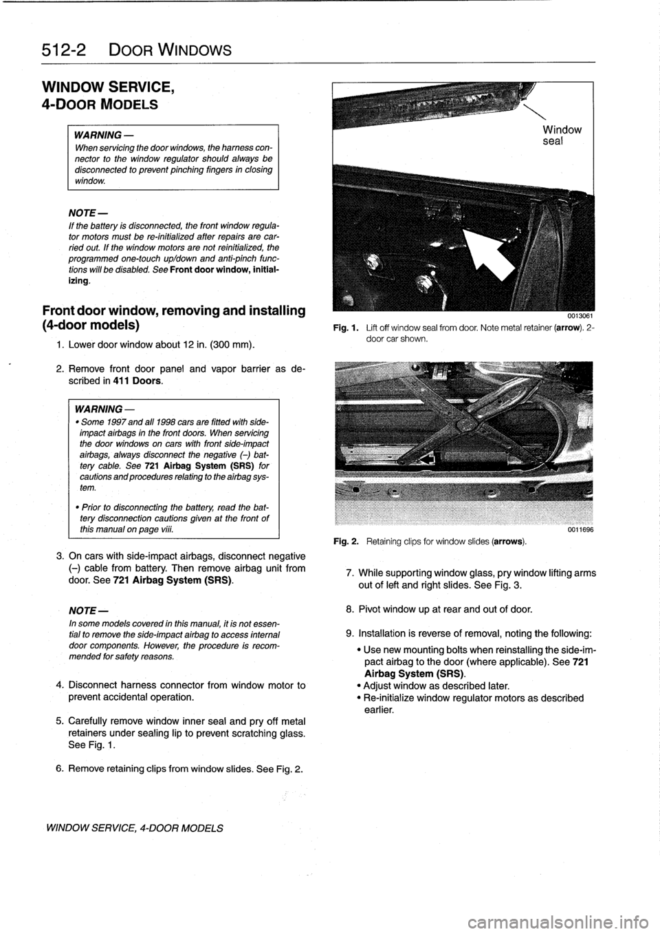
0013061
(4-door
modeis)
Fig
.1.
Lift
off
window
sea¡
from
door
.
Note
metal
retainer
(arrow)
.
2-
door
car
shown
.
1
.
Lower
door
window
about
12
in
.
(300
mm)
.
2
.
Remove
front
door
panel
and
vapor
barrieras
de-
scribed
in
411
Doors
.
WARNING
-
"
Some
1997
and
all
1998
cars
are
fitted
wlth
side-
impact
airbags
in
the
front
doors
.
When
servicing
the
door
wíndows
on
cars
with
front
side-impact
airbags,
always
disconnect
the
negative
()
bat-
tery
cable
.
See
721Airbag
System
(SRS)
for
cautions
and
procedures
relating
to
theairbag
sys-
tem
.
"
Prior
to
disconnectiog
the
battery,
read
the
bat-
tery
disconnection
cautions
given
at
the
front
of
this
manual
on
page
vi¡¡
.
3
.
On
cars
with
side-impact
airbags,
disconnect
negative
(-)
cable
from
battery
.
Then
remove
airbag
unit
fromdoor
.
See
721
Airbag
System
(SRS)
.
5
.
Carefully
remove
window
innersea¡
and
pry
off
metal
retainers
under
sealing
lip
to
prevent
scratchingglass
.
See
Fig
.
1
.
6
.
Remove
retaining
clips
from
window
slides
.
See
Fig
.
2
.
WINDOW
SERVICE,
4-DOOR
MODELS
Fig
.
2
.
Retaining
clipsfor
window
slides
(arrows)
.
0011696
7
.
While
supporting
window
glass,
pry
window
lifting
arms
out
of
left
and
right
slides
.
See
Fig
.
3
.
NOTE-
8
.
Pivot
window
up
at
rear
and
out
of
door
.
In
some
modeis
covered
inthis
manual,
it
is
not
essen-
tial
to
remove
the
side-impact
airbag
to
access
internal
9
.
Installation
is
reverse
of
removal,
notingthe
following
:
door
components
.
However,
the
procedure
is
recom-
"
Usenew
mounting
bolts
when
reinstalling
the
side-im-
mended
forsafety
reasons
.
pactairbag
to
the
door(where
applicable)
.
See
721
Airbag
System
(SRS)
.
4
.
Disconnect
harness
connector
from
window
motor
to
"
Adjust
window
as
described
later
.
prevent
accidental
operation
.
"
Re-initialize
window
regulator
motorsas
described
earlier
.