seat BMW 325i 1993 E36 Owner's Manual
[x] Cancel search | Manufacturer: BMW, Model Year: 1993, Model line: 325i, Model: BMW 325i 1993 E36Pages: 759
Page 114 of 759
117-
1
8
CAMSHAFT
TIMING
CHAIN
CAUTION-
It
is
crítical
that
the
exhaustcamshaft
sprocket
be
turned
only
the
mínimum
amount
necessary
to
engage
the
gear
cup
.
If
this
procedure
is
done
ín-
correctly,
the
VANOS
system
may
not
function
throughout
íts
full
range
.
NOTE-
As
the
control
unit
isinstalled,
the
secondary
sprockets
will
rotate
in
the
counterclockwise
direction
.
It
may
be
necessary
to
guide
sprockets
counterclockwise
as
the
control
unit
is
installed
.
8
.
On
cars
built
from3/95
:
Use
a
spanner
tool
(See
Fig
.
39
.),
turn
exhaust
sprocket
counterclockwise
(as
víewed
from
front
of
engine)
only
enough
to
mesh
gear
cup
splines
with
camshaftgear
.
Slowly
push
VANOS
control
unit
towards
camshaft
until
it
is
fully
seated,guiding
chains
in
counterclockwise
direction
.
CA
UTION-
Ensure
that
the
first
available
tooth
engages
.
9
.
Install
and
tightencontrol
unit
nuts
and
bolt
.
10
.
Connect
harness
connector
to
VANOS
solenoid
.
Using
new
seals,
insta¡¡
oil
line
fitting
.
Tightening
Torques
"
VANOS
control
unitto
cylinder
head
M6
nut
.....
..
..
.
.
.............
10
Nm
(89
in-lb)
M8
bolt
.....
.
.
.
.
..
.............
22
Nm
(17
ft-Ib)
"
VANOS
oil
supply
line
to
control
unit
.
32
Nm
(24
ft-Ib)
11
.
Slowlyunlock
and
release
secondary
chain
tensioner
.
12
.
Preloadprimary
chain
by
tightening
BMW
special
tool
no
.
112
240
(dummy
chain
tensioner)
to
1
.3
Nm
(11
in-
lb)
.
Then
tighten
exhaust
camshaft
sprocket
mounting
bolts
alternately
in
two
stages
.
Tightening
Torque
"
Secondarytiming
chain
sprockets
to
camshafts
(Tora
boits)
Stage
1
..
...............
...
.
.
...
5
Nm
(44
in-lb)
Stage
2
..
...............
...
.
.
..
22
Nm
(17
ft-Ib)
VANOS
(VARIABLE
VALVE
TIMING)
13
.
Remove
flywheel
locking
tool
from
transmission
bell-
housing
.
Remove
camshaft
locking
tool
from
rear
of
cylinder
head
.
14
.
Turn
engine
over
by
hand
at
least
two
fui¡
crankshaft
ro-
tations
.
Reinstall
camshaft
locking
tool
and
flywheel
locking
toolto
make
sure
all
adjustments
are
correct
.
If
settings
are
correct,
remove
locking
tools
.
15
.
Remove
BMW
special
tool
112
420
(dummy
chain
ten-
sioner)
from
side
of
cylinder
head
.
Install
primary
chain
tensioner
so
that
cutout
in
tensioner
piston
engages
chain
rail
.
See
Fig
.
34
.
Using
new
seals,
install
and
tighten
access
plugs
in
VANOS
control
unit
.
Tightening
Torque
"
Access
plugs
to
VANOS
control
unit
.
..
.
.....
.
..
...
50
Nm
(37
ft-lb)
"
Primary
timing
chain
tensioner
plug
to
tensioner
sleeve
M50/S50USengine
.
.
..
.
.
...
.
...
..
50
Nm
(37
ft-Ib)
M52/S52US
engine
...
..
...
...
...
40
Nm
(30
ft-Ib)
16
.
Install
oil
baffle
cover
above
intake
camshaft
.
Install
three
cylinder
head
covermounting
studs
to
rear
of
head
.
Instali
cylinder
head
cover
.
Tightening
Torque
"
Cylinder
head
cover
to
cylinder
head
(M6
screws)
......
10
Nm
(89
in-Ib)
17
.
Installationof
remaining
parts
is
reverse
of
removal
.
NOTE-
Be
sure
to
install
the
ground
wíres
at
the
cylinder
head
cover
mounting
studs
and
at
the
front
of
the
cylinder
head,
if
applicable
.
Page 159 of 759
6
.
Remove
fuel
rail
mounting
bolts
.
See
Fig
.
17
.
0012504
Fig
.
17
.
Location
of
fuel
rail
mounting
bolts
(A)
and
fuel
inlet
and
return
lines
(B)
on
M44
engine
.
Upper
manifold
has
been
removed
.
7
.
Pull
upon
fuel
rail
and
remove
injector
rail
with
injec-tors
.
Remove
individualinjectors
by
removing
injector
retaining
clip
and
pullinginjector
from
rail
.
See
Fig
.
18
.
Fig
.
18
.
Pry
retaining
clip
from
injector
(1),
then
pull
injector
from
rail
(2)
.
8
.
Installation
is
reverse
of
removal
.
Tightening
Torque
"
Fuel
rail
to
cylinder
head
..
.
..
..
...
10
Nm
(89
in-lb)
FUEL
INJECTION
130-
1
3
Fuel
Pressure
Regulator
The
fuel
pressure
regulator
location
on
E36
models
is
mounted
in
one
of
two
locations
:
Fuel
Pressure
Regulator
Location
"
4-cylinder
engines
1992-
January
1997
............
...
..
on
fuel
rail
January
1997-
on
...............
..
...
under
car
"
6-cylinderengines
1992-1995
.
.
...
...
.
...........
...
..
on
fuel
rail
1996-on
..
.
..
................
...
...
undercar
Fuel
pressure
regulator,
replacing
(fuel
rail
mount)
WARNING
-
Fuel
will
be
discharged
.
Do
not
disconnect
any
wires
that
could
cause
electrícal
sparks
.
Do
not
smoke
or
work
near
heaters
or
other
fire
hazards
.
Keepan
approved
fire
extinguisher
handy
.
9
.
On
6-cylinder
engines,
remove
top
engine
covers
.
Re-
move
fuel
rail
mounting
bolts
and
lift
up
fuel
rail
.
1
.
Disconnect
vacuum
hose
from
fuel
pressure
regulator
.
See
Fig
.
19
.
"
Fit
new
O-rings
when
installing
injectors
.
For
ease
of
installation,
lightly
lubricate
O-rings
with
SAE
90
or
0012732
equivalent
lubricant
.
Fig
.
19
.
Fuel
pressure
regulator
(arrow)
on
M42
engine
.
Vacuum
hose
"
Check
that
injector
electrical
connections
are
correctly
shown
at
A
.
fitted
and
that
injectors
are
fully
seated
prior
to
install-
ing
fuel
rail
mounting
bolts
.
2
.
Remove
bolt
from
regulator
clamp
.
Remove
clamp
.
Note
"
Replace
wire
ties
.
installed
direction
of
regulator
to
fuel
rail
.
3
.
Wrap
a
shop
rag
around
regulator,
then
remove
regula-
tor
from
fuel
rail
by
pulling
straight
out
.
FUELDELIVERYTESTS
Page 160 of 759
130-
1
4
FUEL
INJECTION
NOTE-
Be
sure
to
retrieve
thrust
washer
behind
fuel
pressure
regulator
on
6-cylinder
engine
.
4
.
Installation
is
reverse
of
removal
.
Replace
O-rings
.
Fuel
pressure
regulator,
replacing
(under
car
mount)
WARNING
-
Fuel
will
be
discharged
.
Do
not
disconnect
any
wires
that
could
cause
electrical
sparks
.
Do
not
smoke
or
work
near
heaters
or
other
fire
hazards
.
Keep
an
approved
tire
extinguisher
handy
.
On
late
4-
and
6-cylinder
cars,
the
fuel
pressure
regulator
is
mounted
beneath
the
left
sideof
the
car,
under
a
protective
cover
.
See
Fig
.
20
.
0012726
Fig
.
20
.
Fuel
pressure
regulatorlocation
underneath
car
(arrow)
.
Vac-
uum
hose
to
regulator
is
shown
at
A
.
(Protective
cover
has
been
removed
.)
5
.
Installation
is
reverse
of
removal
.
Replace
O-rings
.
BOSCH
DME
Ml
.
7
COMPONENT
TESTS
AND
REPAIRS
BOSCH
DME
Ml
.7
COMPONENT
TESTS
AND
REPAIRS
CA
UTION-
Use
only
a
digital
multimeter
when
testing
compo-
nents
and
wiring
.
Use
of
an
analog
VOM
may
damage
the
engine
control
module
.
4-cylinder
cars
with
M42
engines(1992
to
1995)use
the
Bosch
DME
M1
.7
fuel
injection
system
.
Electrical
tests
of
the
main
and
fuel
pump
relays
and
the
DME
engine
control
module
(ECM)
are
covered
earlier
in
this
section
.
Fuel
pump
tests
arecovered
in
160
Fuel
Tank
and
Fuel
Pump
.
Air
flow
sensor,
testing
and
replacing
DME
M1
.7
fuel
injection
uses
a
volume
air
flow
type
sensor
with
integrated
intake
air
temperature
(IAT)
sensor
.
The
sen-
sor
provides
a
varyingvoltage
signal
to
the
ECM
based
on
the
position
of
the
air
vane
.
As
the
vane
doorswings
open
thepo-
tentiometer
increases
the
voltage
signal
to
the
ECM
.
The
IATsensor
adapts
theoutput
signal
to
the
ECM
based
on
intake
air
temperature
.
1
.
Check
ECM
reference
voltage
to
sensor
:
"
Peel
back
rubber
boot
from
air
flow
sensor
harness
connector
.
"
Turn
ignition
keyon
.
"
Check
for
5
volts
between
terminal
1
of
harness
con-
nector
and
ground
.
See
Fig
.
21
.
"
Turn
ignition
key
off
.
"
If
voltage
is
not
present
or
incorrect,
check
wring
from
ECM
and
check
air
flow
sensor
reference
voltage
out-
put
at
ECM
.
See
Table
h
.
1
.
Working
under
car
below
driver's
seat,
remove
protec-
tive
cover
from
below
fuel
pressure
regulator
.
"
Remove
intake
air
bootfrom
sensor
.
2
.
Remove
vacuum
hosefrom
fuel
pressure
regulator
.
"
Connect
a
digital
multimeter
(ohms)
across
terminais
1
and
2
.
Swing
air
flow
sensor
vane
through
its
travel
3
.
Remove
locking
clip
retaining
fuel
pressure
regulator
.
range
.
Resistance
should
change
steadily
without
in-
terruption
.
4
.
Wrap
a
shop
rag
around
regulator,
then
remove
regula-
"
If
any
faults
are
found,
the
air
flow
sensor
is
faulty
and
tor
from
213
way
valve
by
pullingstraight
out
.
should
be
replaced
.
2
.
Check
air
flow
sensor
potentiometer
:
3
.
Check
IAT
sensor
resistance
:
"
With
harness
connector
disconnected
at
air
flow
sen-
sor,
check
resistance
across
sensor
terminais
4
and
5
of
air
flow
sensor
.
Compare
tests
results
to
values
in
Table
d
given
later
.
If
any
faults
are
found,
the
air
flow
sensor
should
be
replaced
.
Page 168 of 759
130-
2
2
FUEL
INJECTION
Mass
air
flow
sensor,
replacing
1
.
Disconnect
harness
connector
and
intake
air
bootfrom
air
flow
sensor
.
See
Fig
.
32
.
Fig
.
32
.
To
detach
air
flow
sensor,
disconnect
harness
connector
(A)
;
3
.
Installation
is
reverse
of
removal
.
unclip
retainíng
clips
to
aír
filter
housing
(B)
;
andremove
large
hose
clamp
at
air
intake
bellows
(C)
.
M44
engine
with
traction
"
Use
a
new
copper
sealing
washer
when
installing
sen-
control
shown
.
sor
.
"
Replace
any
lost
coolant
.
2
.
Detachtwo
large
clipsat
air
filter
housing
and
work
air
flow
sensor
out
of
rubber
seal
in
filter
housing
.
Tightening
Torque
3
.
Installation
is
reverse
of
removal
.
"
Engine
coolant
temperature
"
For
ease
of
installation,
lubricate
large
rubber
seal
in
to
cylinder
head
.............
.
..
.
13
Nm
(10
ft-Ib)
air
filter
housing
with
silicone
lubricant
or
equivalent
.
"
No
adjustment
to
air
flow
sensor
is
possible
.
"
Carefully
check
that
all
hoses
and
seals
are
seated
Intake
air
temperature
(IAT)
sensor,
properly
.
replacing
Engine
coolant
temperature
(ECT)
sensor,
replacing
The
engine
coolant
temperature
(ECT)sensor
is
a
dual
temperature
sensor
.
One
circuít
provides
coolant
temperature
information
to
the
ECM
while
the
other
circuít
provides
coolant
temperature
information
to
the
instrument
cluster
.
WARNING
-
Do
not
replace
the
ECT
sensor
unless
the
engine
is
cold
.
Hot
coolant
can
scald
.
1
.
Disconnect
harness
connector
from
ECT
sensor
.
See
Fig
.
33
.
2
.
Unscrew
temperature
sensorfrom
cylinder
head
and
remove
BOSCH
DME
M5
.2
COMPONENT
REPLACEMENT
U1111
bis4a
Fig
.
33
.
M44
engine
coolant
temperature
(ECT)
sensor
located
above
oil
filter
(arrow)
.
The
intake
air
temperature
(IAT)
sensoron
cars
with
M44
engine
is
mounted
in
thetop
section
of
the
intake
air
filter
housing
.
See
Fig
.
34
.
1
.
Remove
electrical
harness
connector
from
IAT
sensor
.
2
.
Unclip
temperature
sensor
and
remove
from
air
filter
housing
.
3
.
Installation
is
reverse
of
removal
.
Throttle
position
sensor
(TPS),
replacing
The
throttle
position
sensor
is
located
on
the
side
of
the
throttle
housing
.
See
Fig
.
35
.
1
.
Unplug
harness
connector
from
sensor
.
Page 186 of 759
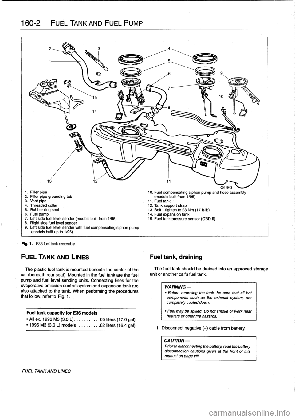
160-2
FUEL
TANK
AND
FUEL
PUMP
0011943
1
.
Filler
pipe
10
.
Fuel
compensating
siphon
pump
and
hose
assembly
2
.
Filler
pipe
grounding
tab
(models
built
from
1/95)
3
.
Vent
pipe
11
.
Fueltank
4
.
Threaded
collar
12
.
Tank
support
strap
5
.
Rubber
ring
seal
13
.
Bolt-tighten
to
23
Nm
(17
ft-Ib)
6
.
Fuel
pump
14
.
Fuel
expansion
tank
7
.
Left
side
fuel
leve¡
sender(models
built
from
1/95)
15
.
Fuel
tank
pressure
sensor
(OBD
II)
8
.
Right
side
fuel
leve¡
sender9
.
Left
side
fuel
leve¡
sender
with
fuel
compensating
siphon
pump
(models
built
up
to
1/95)
Fig
.
1
.
E36
fuel
tank
assembly
.
FUEL
TANK
AND
LINES
Fuel
tank,
draining
The
plastic
fuel
tank
is
mounted
beneath
the
center
of
the
car
(beneath
rear
seat)
.
Mounted
in
the
fuel
tank
are
the
fuel
pump
and
fuel
leve¡
sending
units
.
Connecting
lines
for
the
evaporative
emission
control
systemand
expansion
tank
are
also
attached
to
the
tank
.
When
performing
the
procedures
that
follow,
refer
toFig
.
1
.
Fuel
tank
capacity
for
E36
modeis
"All
ex
.
1996
M3
(3
.0
L)
.....
.
..
..
65
liters
(17
.0
gal)
"
1996
M3
(3.0L)
modeis
.
...
.
..
.
.62
liters
(16
.4
gal)
FUEL
TA
NKAND
LINES
The
fuel
tank
should
be
drained
into
an
approved
storage
unit
or
another
car's
fuel
tank
.
WARNING
-
"
Before
removing
the
tank,
be
sure
that
afl
hot
components
such
as
the
exhaust
system,
are
completely
cooled
down
.
"
Fuel
may
be
spilled
.
Do
not
smoke
or
worknear
heaters
or
other
Pire
hazards
.
1
.
Disconnect
negative
(-)
cable
from
battery
.
CAUTION-
Prior
to
disconnectiog
the
battery,
read
the
battery
disconnection
cautions
given
at
the
front
of
this
manual
on
paga
vi¡¡
.
Page 187 of 759
2
.
Remove
fuel
tank
filler
cap
.
3
.
Remove
rearseat
cushion
and
pull
back
insulation
mats
to
expose
fuel
tank
access
covers
.
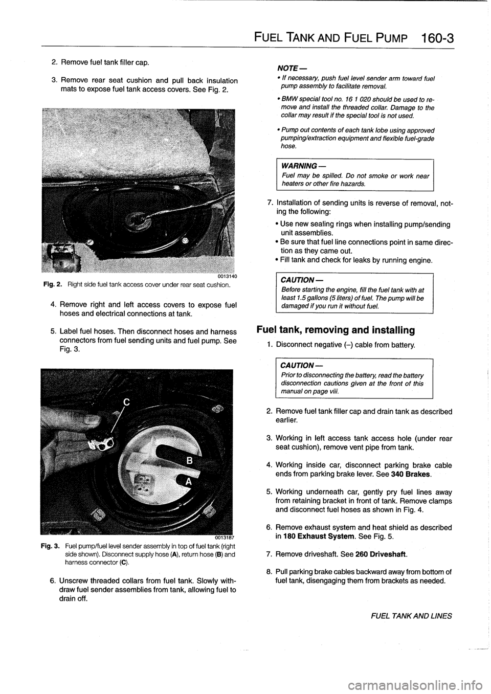
See
Fig
.
2
.
uui3140
Fig
.
2
.
Right
side
fuel
tank
access
cover
under
rear
seat
cushion
.
4
.
Remove
right
and
left
access
covers
to
expose
fuel
hoses
and
electrical
connections
at
tank
.
5
.
Label
fuel
hoses
.
Then
disconnect
hoses
and
harness
connectors
from
fuel
sending
units
and
fuel
pump
.
See
Fig
.
3
.
FUELTANK
AND
FUEL
PUMP
160-
3
NOTE-
"
If
necessary,
push
fuel
level
sender
arm
toward
fuel
pump
assembly
to
facilitate
removal
.
"
BMW
special
tool
no
.
16
1
020
should
beused
tore-
move
and
install
the
threaded
collar
.
Damage
to
thecollar
may
result
if
the
special
tool
is
not
used
.
"
Pump
out
contents
of
each
tanklobe
using
approved
pumpinglextraction
equipment
and
flexible
fuel-grade
hose
.
WARNING
-
Fuel
may
be
spilled
.
Do
not
smoke
or
work
near
heaters
or
other
fire
hazards
.
7
.
Installation
of
sending
units
is
reverse
of
removal,
not-
ing
the
following
:
"
Use
new
sealing
rings
when
installing
pump/sending
unit
assemblies
.
"
Be
sure
that
fuel
line
connections
point
in
same
direc-tion
as
they
carne
out
.
"
Fill
tank
and
check
for
leaks
by
running
engine
.
CA
UTION-
Before
starting
the
engine,
fill
the
fuel
tank
with
at
least
1.5
gallons
(5liters)
of
fuel
.
The
pump
will
be
damaged
if
you
run
it
without
fuel
.
Fuel
tank,
removing
and
installing
1.
Disconnect
negative
(-)cablefrom
battery
:
CAUTION-
Prior
to
disconnectiog
the
battery,
read
the
battery
disconnection
cautions
given
at
the
front
of
this
manual
onpage
viii
.
2
.
Remove
fuel
tank
filler
capand
drain
tank
as
described
earlier
.
3
.
Working
in
left
access
tank
access
hole
(under
rear
seat
cushion),
remove
vent
pipe
fromtank
.
4
.
Working
inside
car,
disconnectparking
brake
cable
ends
from
parking
brake
lever
.
See
340
Brakes
.
5
.
Working
underneath
car,
gently
pry
fuel
lines
away
from
retaining
bracket
in
front
of
tank
.
Remove
clamps
and
disconnect
fuel
hoses
as
shown
in
Fig
.
4
.
6
.
Remove
exhaust
system
and
heat
shield
as
described
ooisiai
in
180
Exhaust
System
.
See
Fig
.
5
.
Fig
.
3
.
Fuel
pump/fuel
level
sender
assembly
in
top
offuel
tank
(right
side
shown)
.
Disconnect
supply
hose
(A),
return
hose
(B)
and
7
.
Remove
driveshaft
.
See
260
Driveshaft
.
harness
connector
(C)
.
8
.
Pull
parking
brake
cables
backward
away
from
bottom
of
6
.
Unscrew
threaded
collars
from
fuel
tank
.
Slowly
with-
fuel
tank,
disengaging
them
from
brackets
as
needed
.
draw
fuel
sender
assemblies
from
tank,allowing
fuel
to
drain
off
.
FUEL
TANKAND
LINES
Page 189 of 759
Fuel
leve¡
senders,
testing
Fuel
leve¡
sender
(right
side)
The
left
and
right
fuelleve¡
sending
units
are
wired
in
series
.
and
fuel
pump,
removing
and
installing
The
fuel
gauge
receives
a
signal
that
is
the
average
of
the
two
1
.
Disconnect
negative
(-)
cable
from
battery
.
input
values
.
1
.
Remove
rear
seat
cushion,
lift
up
insulation
mats,
andremove
both
fuel
tank
access
covers
.
2
.
Disconnect
white
plug
on
each
sending
unit
.
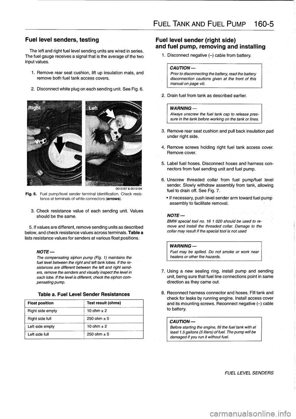
See
Fig
.
6
.
3
.
Check
resistance
value
of
eachsending
unit
.
Values
should
be
the
same
.
5
.
If
valuesare
different,
remove
sending
units
as
described
below,
and
check
resistance
valuésacross
terminals
.
Table
a
lists
resistance
values
for
senders
at
various
float
positions
.
Table
a
.
Fuel
Leve¡
Sender
Resistances
Float
position
Test
result
(ohms)
Right
side
empty
10
ohm
t2
Right
side
full
250
ohm
±
5
Left
side
empty
10
ohm
t
2
Left
side
fui¡
250
ohm
±
5
FUEL
TANK
AND
FUEL
PUMP
160-
5
CAUTION
-
Prior
to
disconnecting
the
battery,
read
the
battery
disconnection
cautionsglven
at
the
front
of
this
manual
onpage
viii
.
2
.
Drain
fuel
from
tank
as
described
earlier
.
WARNING
-
Always
unscrew
the
fuel
tank
cap
to
release
pres-
sure
in
the
tank
before
working
on
the
tank
or
fines
.
3
.
Remove
rear
seat
cushion
and
pull
back
insulation
pad
under
right
side
.
4
.
Remove
screws
holding
rightfuel
tank
accesscover
.
Remove
cover
.
5
.
Label
fuel
hoses
.
Disconnect
hoses
and
harness
con-
nectors
from
fuel
sending
unit
and
fuel
pump
.
6
.
Unscrew
threaded
collar
from
fuel
pumplfuel
leve¡
sender
.
Slowly
withdraw
assembly
from
tank,allowing
fuelto
drain
off
.
See
Fig
.
7
.
0013187
&
0013194
Fig
.
6
.
Fuel
pump/leve¡
sender
terminal
identification
.
Check
resis-
tance
at
terminals
of
white
connectors
(arrows)
.
"
If
necessary,
push
leve¡
sender
arm
toward
fuel
pump
assembly
to
facilitate
removal
.
NOTE
-
BMW
special
tool
no
.
16
1
020
should
beused
to
re-
move
and
install
the
threaded
collar
.
Damage
to
the
collar
may
result
if
the
special
tool
is
not
used
WARNING
-
NOTE-
Fuel
may
be
spilled
.
Do
not
smoke
or
work
near
The
compensating
siphon
pump
(Fig
.
1)
maintains
the
heaters
or
other
fire
hazards
.
fuel
leve¡
between
the
right
and
left
tank
lobes
.
If
the
re-
sistances
are
different
between
the
left
and
right
send-
ers,
remove
the
senders
and
visually
inspect
the
leve)
in
7
.
Using
a
new
sealing
ring,
install
pump
and
sending
each
lobe
.
If
the
leve¡
is
different,
check
the
siphon
com-
unit,
being
sure
that
fuel
line
connections
point
in
same
pensating
pump
.
direction
as
they
carne
out
.
8
.
Reconnect
harnessconnector
and
hoses
.
Fill
tank
and
check
for
leaks
by
running
engine
.
Insta¡¡
access
cover
and
its
mountingscrews
.
Reconnect
negative
(-)
cable
to
battery
.
CAUTION
-
Before
starting
the
engine,
fill
the
fuel
tank
with
at
least
1
.5
gallons
(5liters)
of
fuel
.
The
pump
will
be
damaged
if
you
run
it
without
fuel
.
FUEL
LEVEL
SENDERS
Page 191 of 759
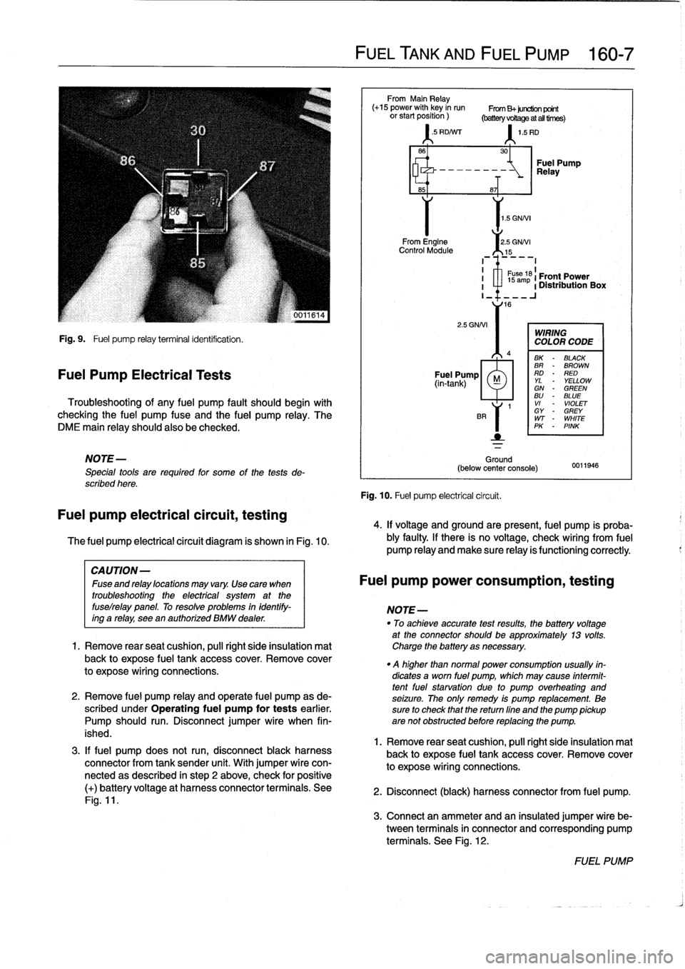
Fig
.
9
.
Fuel
pump
relay
terminal
identification
.
Fuel
Pump
Electrical
Tests
Troubleshooting
of
any
fuel
pump
fault
should
begin
with
checking
the
fuel
pump
fuse
and
the
fuel
pump
relay
.
The
DME
main
relay
should
also
be
checked
.
NOTE-
Special
tools
are
requíred
for
some
of
the
tests
de-
scribed
here
.
Fuel
pump
electrical
circuit,
testing
The
fuel
pump
electrical
circuit
diagram
is
shown
in
Fig
.
10
.
3
.
If
fuel
pump
does
not
run,
disconnect
black
harness
connector
from
tank
sender
unit
.
With
jumper
wire
con-
nectedas
described
in
step
2
above,
check
for
positive
(+)
batteryvoltage
at
harness
connector
terminals
.
See
Fig
.
11
.
FUEL
TANK
AND
FUEL
PUMP
160-
7
From
Main
Relay
(+15
power
with
key
in
run
From
B+juretion
point
orstartposition)
(batteryvoRageatalltirnes)
'
.5
RD/Nrr
1
.5
RD
1
.5
GNNI
From
Engine
2
.5
GNNI
Control
Module
15
2
.5
GNNI
Ground
(below
center
console)
Fig
.
10
.
Fuel
pump
electrical
circuit
.
30
-~
Relay
Fuel
Pump
8~T
I
1
s
ám
61
Front
Power
I
a
1
Distribution
Box
I_
16
WIRING
COLOR
CODE
BK
-
BLACK
BR
-
BROWN
Fuel
Pump
RD
-
RED
(in-tank)
M
YL
YELLOWGN
-
GREENBU
-
BLUE
1
VI
-
VIOLET
GY
-
GREY
WT
-
WHITE
PK
-
PINK
0011946
4
.
If
voltage
and
groundare
present,
fuel
pump
is
proba-
bly
faulty
.
If
there
is
no
voltage,
check
wiring
From
fuel
pump
Reay
and
make
sure
Reay
is
functioning
correctly
.
CAUTION-
Fuseandrelaylocationsmayvary
.
Usecara
when
Fuel
pump
power
consumption,
testing
troubleshooting
the
electrical
system
at
the
fuselrelay
panel
.
To
resolve
problems
in
identify-
NOTE-
ing
a
relay,
see
en
authorízed
BMW
dealer
.
"
To
achieveaccurate
testresults,
fhe
battery
voltage
at
the
connector
should
be
approximately
13
volts
.
1.
Remove
rearseat
cushion,
pull
right
side
insulation
mat
Charge
the
battery
asnecessary
.
back
to
expose
fuel
tank
accesscover
.
Remove
cover
.
q
higher
than
normal
power
consumption
usually
fin-
to
expose
wiring
connections
.
dicates
a
worn
fuel
pump,
which
may
cause
intermit-
tentfuel
starvation
due
lo
pump
overheating
and
2
.
Remove
fuel
pump
relay
and
opérate
fuel
pump
as
de-
seizure
.
The
only
remedy
is
pump
replacement
.
Be
scribed
under
Operating
fuel
pump
for
tests
earlier
.
sure
to
check
that
thereturn
fine
and
the
pump
pickup
Pump
should
run
.
Disconnect
jumper
wire
when
fin-
are
not
obstructed
before
replacing
the
pump
.
ished
.
1
.
Remove
rear
seat
cushion,
pull
right
side
insulation
mal
back
to
expose
fuel
tank
accesscover
.
Remove
cover
to
expose
wiring
connections
.
2
.
Disconnect
(black)
harness
connector
from
fuel
pump
.
3
.
Connect
an
ammeter
and
an
insulated
jumper
wire
be-
tween
terminals
in
connector
and
corresponding
pump
terminals
.
See
Fig
.
12
.
FUEL
PUMP
Page 219 of 759
Clutch,
inspecting
and
installing
1
.
Inspect
clutch
disc
for
wear,
cracks,
loose
rivets,
con-
tamination
or
excessive
runout
(warping)
.
Replace
if
necessary
.
2
.
Inspect
flywheel
for
scoring,
hot
spots,
cracks
or
loose
or
worn
guide
pins
.
Replace
flywheel
if
any
faults
are
found
.
WARNING
-
If
flywheel
is
removed
from
vehicle,
use
new
bolts
duríng
installation
.
The
old
stretch-typebolts
should
not
be
reused
.
3
.
Inspecttransmission
pilot
bearing
in
end
of
crankshaft
.
The
bearing
should
rotate
smoothly
without
play
.
If
nec-
essary,
replace
as
described
later
.
4
.
Inspect
and
clean
releasebearing
lever
.
Apply
a
thin
coat
of
grease
to
releasebearíng
lever
contact
points
.
See
Fig
.
9
.
Also,
lightly
lubricate
clutch
disc
splines
and
transmission
inputshaft
splínes
.
5
.
Install
pressure
plate
and
clutch
disc
.
Do
not
fully
tight-
en
bolts
.
6
.
Center
clutch
disc
on
flywheel
using
centering
tool
(BMW
special
tool
no
.
21
2
130
or
equivalent)
.
Refer
to
Fig
.
7
.
NOTE-
Be
sure
clutchdísc
is
facing
the
correct
way
.
The
new
disc
should
bemarked
engine
sfde
or
transmission
side
.
See
Fig
.
10
.
7
.
Tighten
each
bolt
one
turn
at
a
time
until
pressure
plate
is
fully
seated,
and
then
torque
to
specification
.
8
.
Remove
clutch
disc
centering
tool
.
Remove
flywheel
locking
tool
.
Fig
.
9
.
Clutch
release
lever
lubrication
points
(arrows)
.
CLUTCH
210-
5
Clutch
Clutch
pressure
disc
plate
0012026
Fig
.
10
.
Clutch
assembly
Note
clutch
disc
hub
position
during
instal-
lation
.
CLUTCH
MECHANICAL
Page 234 of 759
240-
6
AUTOMATIC
TRANSMISSION
14
.
Remove
transmission
by
pulling
back
and
down
.
Lower
jack
to
allow
transmission
to
clear
vehicle
.
Tightening
Torques
"
ATF
drain
plug
to
ATF
sump
CA
UTION-
MS
270R/A4S
310R
....
..
....
.
..
25
Nm
(18
ft-Ib)
Do
not
allow
the
torque
converter
to
fati
off
the
ASS
310Z(M10
plug)
..
..
..
.
.
..
.
..
16
Nm
(12
ft-Ib)
transmission
inputshaft
.
"
ATF
fill
plug
to
ATF
sump
MS
270R/A4S
310R
..
..
....
..
..
.
33
Nm
(24
ft-Ib)
15
.
Installation
is
reverse
of
removal,
noting
the
following
:
MS
310Z(M30
plug)
......
.
.
..
.
.
100
Nm
(74
ft-Ib)
"Blowoutofcoolerlineswithlow-pressurecompressed
"
ATF
cooler
lines
(A4S
270R/A4S
310R)
air
and
flush
coolerwith
clean
ATF
twice
before
reat-
Coupling
nuts
............
.
.
..
..
.
20
Nm
(15
ft-Ib)
taching
lines
to
transmission
.
Hollow
bolts
.........
.
.....
..
..
.
37
Nm
(28
ft-Ib)
"
Reinforcing
cross
brace
CAUTION-
to
chassis
(M10)
.............
.
..
.
42
Nm
(31
ft-Ib)
"
Wear
safety
glasses
when
working
with
com-
"
Torque
converter
pressedair
.
to
driveplate
(M10)
.........
..
.
..
45
Nm
(33
ft-Ib)
"
Transmissionsupport
crossmember
to
chassis
"
Do
not
reuse
ATF
after
flushing
.
M8
......................
22-24
Nm
(16-17
ft-1b)
M10
................
.
....
..
.
..
42
Nm
(31
ft-Ib)
"
Install
new
sealing
washers
on
hollow
bolts
.
"
Transmissíon
to
engine
(Torx-head
with
washer)
"
Insta¡¡
new
O-rings
on
transmission
cooler
lines,
where
M8
......................
..
.
..
21
Nm
(15
ft-Ib)
applicable
.
M10
.....................
..
..
.
42
Nm
(31
ft-Ib)
"
Inspect
driveplate
for
cracks
or
elongatedholes
.
Re-
M12
................
.
....
..
.
..
72
Nm
(53ft-Ib)
place
if
necessary
.
"
Check
to
be
sure
torque
converter
is
seated
correctly
in
transmission
during
final
installation
.
"
When
mounting
transmission
to
engine,
the
three
mounting
tabs
on
torque
converter
must
be
aligned
with
indentations
on
driveplate
.
Use
an
alignment
dowel
to
line
up
bolt
holes,
if
necessary
.
"
Fill
transmission
with
clean
ATF
until
oil
leve¡
is
even
with
fill
hole
.
Then
check
fluid
leve¡
as
described
ear-
lier
.
"
Adjust
gearshift
mechanism
.
See
250
Gearshift
link-
age
.
NOTE-
Torx-head
mounting
bolts
shouldalwaysbe
used
with
washers
to
prevent
difficult
removal
.
TRANSMISSION
REMOVAL
AND
INSTALLATION