dashboard light BMW 325i 1994 E36 Workshop Manual
[x] Cancel search | Manufacturer: BMW, Model Year: 1994, Model line: 325i, Model: BMW 325i 1994 E36Pages: 759
Page 250 of 759
300-2
SUSPENSION,
STEERING
AND
BRAKES-GENERAL
Steering
INTEGRATED
SYSTEMS
The
steering
linkage
connects
the
rack-and-pinion
unit
through
tie
rodsto
the
steering
arms
.
The
tie
rod
ends
allow
the
wheels
to
pivot
and
react
to
suspension
travel
.
Rear
Suspension
The
rear
axle
carrier
is
the
main
mounting
point
for
the
final
drive
housing
and
the
rear
suspension
components
.
Trailing
arms
locatethe
rear
wheels
and
anchorthe
springs,
shocks
and
stabilizer
bar
.
Driveaxies
with
constant-velocity
(CV)
joints
at
both
ends
transfer
power
from
the
differential
to
the
road
wheels
.
The
differential
is
mounted
to
the
rearaxle
carrier
through
rubber
mountsand
bushings
to
hele
isolate
drivetrain
noise
and
vibration
.
Brakes
E36
cars
areequipped
with
power
disc
brakes
with
an
inte-
gral
antilock
brakes
(ABS)
.
The
parking
brake
is
a
dual-drum
system
integrated
with
the
rear
brake
rotors
.
See
Fig
.
3
.
Power
assist
is
provided
by
a
vacuum
booster
when
the
en-
gine
is
running
.
The
brakepedal
pushrod
is
connected
directly
to
the
master
cylinder,
so
failure
of
the
vacuum
booster
does
not
normally
result
in
total
brake
failure
.
0012124
Each
disc
brakeuses
a
caliper
with
a
single
hydraulic
cylin-
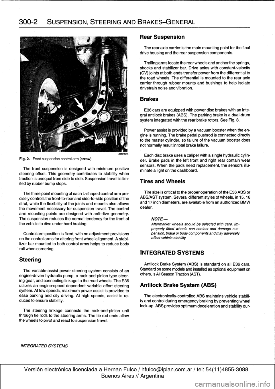
Fig
.
2
.
Front
suspension
control
arm
(arrow)
.
der
.
Brake
pads
in
the
left
front
and
right
rear
contain
wear
sensors
.
When
the
padsneed
replacement,the
sensors
illu-
The
front
suspension
is
designed
with
minimum
positive
minate
a
light
on
the
dashboard
.
steering
offset
.
This
geometry
contributes
to
stability
when
traction
is
unequalfrom
side
to
side
.
Suspension
travel
is
lim-
Tires
and
Wheels
ited
by
rubber
bump
stops
.
The
three
point
mounting
of
each
L-shaped
control
arm
ere-
Tiresize
is
critica¡
to
the
proper
operatíon
of
the
E36
ABS
or
cisely
controls
the
front-to-rear
and
side-to-side
position
of
the
ABS/AST
system
.
Severa¡
different
styles
of
wheels,
in
15,16
strut,
while
the
flexibility
of
the
joints
and
mounts
alsoallows
and
17
inch
diameters,
are
available
from
an
authorized
BMW
the
movement
necessary
for
suspension
travel
.
The
control
dealer
.
arm
mounting
points
are
designed
with
anti-dive
geometry
.
The
suspension
reduces
the
normaltendency
for
the
front
of
NOTE-
the
vehicle
to
dive
under
hard
braking
.
Aftermarket
wheelsshould
be
selected
wlth
care
.
Im-
properly
fitted
wheels
can
contact
anddamage
sus
Control
arm
position
is
fixed,
with
no
adjustment
provisions
pension,
brakeorbodycomponentsandmayadversely
on
the
control
arms
for
alter¡ng
front
wheel
al
ignment
.
A
stabi-
affect
vehicle
stability
.
lizer
bar
mounted
to
both
control
arms
heles
to
reduce
body
rol¡
whencomering
.
INTEGRATED
SYSTEMS
Antilock
Brake
System
(ABS)
is
standard
on
all
E36
cars
.
The
variable-assist
power
steering
system
consists
of
an
Standard
on
some
models
and
installed
as
optional
equipment
on
engine-driven
hydraulic
pump,
a
rack-and-pinion
type
steer-
others,
is
All
Season
Traction
(AST)
.
ing
gear,
and
connecting
linkage
to
the
road
wheels
.
TheE36
utilizes
an
engine-speed
dependent
variable
effort
steering
Antilock
Brake
System
(ABS)
system
.
At
low
speeds,
maximum
power
assist
is
provided
to
ease
parking
and
city
driving
.
Athigh
speeds,
assist
is
re-
The
electronically-controlled
ABS
maintains
vehícle
stabili
duced
to
ensure
stability
.
ty
and
control
during
emergency
braking
by
preventing
wheel
lock-up
.
ABS
provides
optimum
deceleration
and
stability
dur-
Page 302 of 759
340-
1
2
BRAKES
ABS
is
self-tested
by
the
ABS
diagnostic
unit
each
time
the
car
is
started
.
Once
the
test
is
complete,
the
ABS
dashboard
light
tucos
off
.
If
the
light
remains
lit
or
comes
on
at
any
time
during
driving,
a
system
fault
has
occurred
and
ABS
is
elec-
tronically
disabled
.
The
conventional
braking
systemremains
fully
functioning
.
ABS
Inspection
A
visual
inspection
of
the
ABS
may
help
to
locate
system
faults
.
If
no
visual
faults
can
befound
and
the
ABS
light
re-
mains
on,
have
the
system
diagnosedbyan
authorized
BMW
dealer
.
Carefully
inspect
the
entire
ABS
wiring
harness,
particularly
the
pulse
sensorharnesses
and
connectors
near
each
wheel
.
Look
for
chafing
or
damage
due
to
incorrectly
routed
wires
.
Carefully
remove
the
wheelspeed
sensors
.
Clean
the
sen-
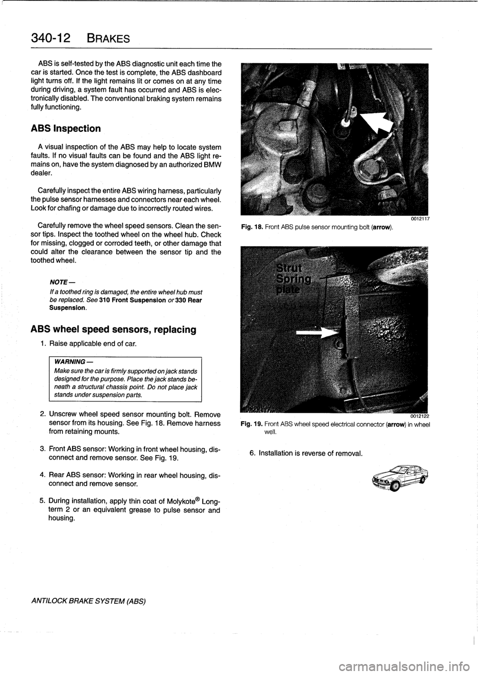
Fig
.
18
.
Front
ABS
pulse
sensor
mounting
bolt
(arrow)
.
sor
tips
.
Inspect
the
toothed
wheel
on
thewheel
hub
.
Check
for
missing,
clogged
or
corroded
teeth,
or
other
damage
that
could
alter
the
clearance
between
the
sensor
tip
and
the
toothed
wheel
.
NOTE-
If
a
toothed
ring
is
damaged,
the
entire
wheel
hub
mustbe
reptaced
.
See
310
Front
Suspension
or330
Rear
Suspension
.
ABS
wheel
speed
sensors,
replacing
1
.
Raise
applicable
end
of
car
.
WARNING
-
Make
sure
thecar
is
firmly
supportedon
jack
stands
designed
for
the
purpose
.
Place
the
jack
stands
be-
neath
a
structural
chassis
point
Do
not
place
jack
stands
under
suspension
parts
.
2
.
Unscrew
wheelspeed
sensor
mounting
bolt
.
Remove
sensor
from
its
housing
.
See
Fig
.
18
.
Remove
harnessfrom
retaining
mounts
.
3
.
Front
ABS
sensor
:
Working
in
front
wheel
housing,
dis-
connect
and
remove
sensor
.
See
Fig
.
19
.
4
.
Rear
ABS
sensor
:
Working
in
rear
wheel
housing,
dis-
connect
andremove
sensor
.
5
.
During
installation,
apply
thin
coat
of
Molykote
0
Long-
term
2
or
an
equivalent
grease
to
pulse
sensor
and
housing
.
ANTILOCK
BRAKE
SYSTEM
(ABS)
0012122
Fig
.
19
.
Front
ABS
wheel
speed
electrical
connector
(arrow)
in
wheel
well
.
6
.
Installation
is
reverse
of
removal
.
Page 306 of 759
400-
4
BODY-GENERAL
INTERIOR
EQUIPMENT
E36
interiors
have
a
unique
character,
with
a
combínation
of
sporty
features
and
innovative
design
.
Al¡
body
versions
were
made
in
a
wide
choice
of
interior
and
exterior
colors
.
New
colors
with
matching
leather
and/or
fabric
upholstery
were
in-
troduced
for
each
model
year,
including
light-alloy
wheels
in
new
designs
.
Driving
comfort
is
enhanced
by
power
steering,
tilt
steering
wheel
(optional),
height-adjustable
front
seats,
and
electrical-
ly
adjustable
and
heated
rear-view
mirrors
.
Inside
thecar
there
are
reading
lights
at
four
seating
positions
.
Seats
and
Seat
Belts
NOTE-
Theseat
base
usedon
cars
with
pyrotechnic
seatbelt
Anatom¡cal
ly-correct
seats
are
constructed
from
polyure-
tensioners
is
not
interchangeable
with
the
earlier
seat
thane
foam
containing
areas
or
"zones"
of
different
firmness
.
base
.
The
seat
bases
have
steel
springs
for
added
support
and
strength
.
The
power
seats
are
provided
with
conveniently
lo-
Instruments
and
Controls
cated
switches
along
the
outside
edge
of
the
seat
.
Heated
seats
are
an
option
in
all
models
.
See
520
Seats
for
more
de-
Everything
in
the
interior
passenger
compartment
essential
tails
.
to
the
driver
is
logically
grouped
and
easy
to
reach
.
Al¡
instru-
ments
and
controls
havebeen
arranged
ergonomically
and
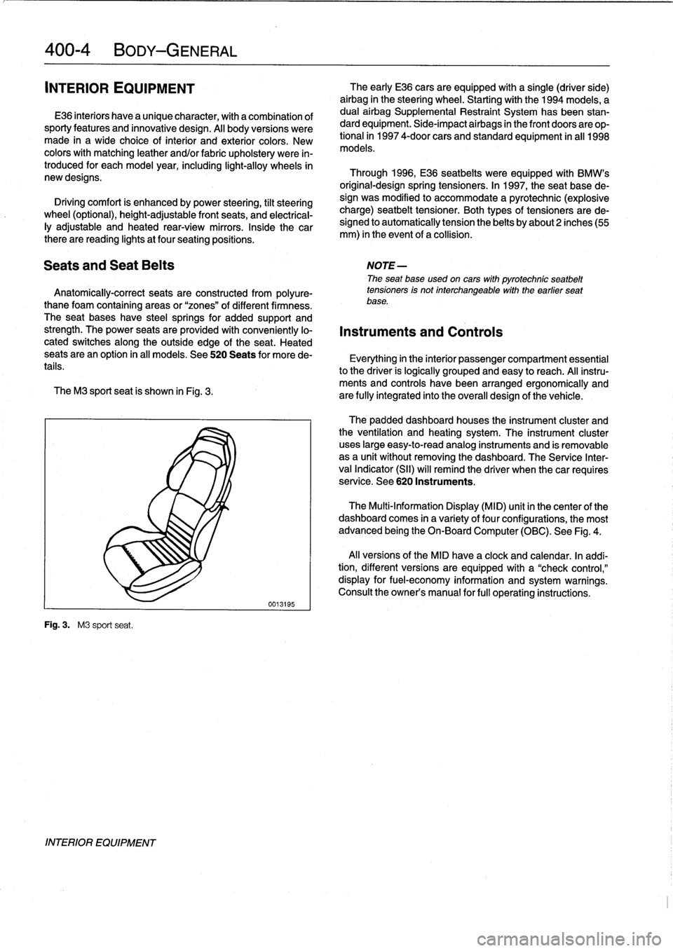
The
M3
sport
seat
is
shown
in
Fig
.
3
.
are
fully
integrated
into
the
overall
design
of
the
vehicle
.
Fig
.
3
.
M3
sport
seat
.
INTERIOR
EQUIPMENT
0013195
The
early
E36
cars
areequipped
with
a
single
(driver
side)
airbag
in
the
steering
wheel
.
Startingwith
the
1994
models,
a
dual
airbag
Supplemental
Restraint
System
has
been
stan-
dard
equipment
.
Side-impact
airbags
in
the
front
doors
are
op-
tional
in
1997
4-door
cars
and
standard
equipment
in
all
1998
models
.
Through
1996,
E36
seatbelts
were
equipped
with
BMW's
original-designspring
tensioners
.
In
1997,
the
seat
base
de-
sign
was
modified
to
accommodate
a
pyrotechnic
(explosive
charge)
seatbelt
tensioner
.
Both
types
of
tensioners
arede-
signed
to
automatically
tension
the
belts
by
about2
inches(55
mm)
in
the
event
of
a
collision
.
The
padded
dashboard
houses
the
instrument
cluster
and
the
ventilation
and
heating
system
.
The
instrument
cluster
uses
large
easy-to-read
analog
instruments
and
is
removable
as
a
unit
without
removing
the
dashboard
.
The
Service
Inter-
val
Indicator
(SII)
will
remind
the
driver
when
thecar
requires
service
.
See
620
Instruments
.
The
Multi-Information
Display
(MID)
unit
in
thecenter
of
the
dashboard
comes
in
a
variety
of
four
configurations,
the
most
advanced
being
the
On-Board
Computer
(OBC)
.
See
Fig
.
4
.
Al¡
versions
of
the
MID
have
a
clock
and
calendar
.
In
addi-
tion,
different
versions
areequipped
with
a
"check
control,"
display
for
fuel-economy
information
and
system
warnings
.
Consult
the
owner's
manual
for
fui¡
operating
instructions
.
Page 345 of 759
GENERAL
This
repair
group
covers
interior
trim
removal
and
installa-
tion
procedures
.
Forremoval
and
installation
of
interior
switches,
including
interior
lighting
equipment,
see
612
Switches
and
Electrical
Accessories
.
Most
of
the
interior
trim
and
finish
paneis
are
clipped
or
screwed
into
place
.
Many
of
the
trim
retaining
clips
arede-
signed
to
be
used
only
once
.
When
removing
trim
that
is
held
in
place
with
clips,
it
is
a
good
idea
lo
have
spareson
hand
be-
fore
beginningthejob
.
CENTER
CONSOLE
The
front
section
center
console
houses
the
Multi-Informa-
tion
Display
(MID)
module,the
front
ashtray
and
cigarette
lighter
;
shifter
lever,
power
window
switches
and
the
hazard
warning
switch
.
The
rear
center
console
section
houses
the
ashtray(s)
and
covers
the
emergency
brakecable
ends
.
Center
console,
removing
and
installing
1
.
Disconnect
negative
(-)
cable
from
battery
and
cover
terminal
with
insulating
material
.
CA
UTION-
Prior
to
disconnectiog
the
battery,
read
the
battery
disconnection
cautionsgiven
at
the
front
of
this
manual
onpage
viii
.
2
.
Remove
shifter
boot
or
selectorlever
cover
.
See250
Gearshift
t-inkage
.
3
.
Remove
rear
ashtray
retaining
screws
totake
out
ash-
tray
.
Remove
rear
console
retaining
screwunder
ash-
tray
.
513
Interior
Tri
m
INTERIORTRIM
513-1
GENERAL
..
.
.....
.
.
.
.
.
.
.
.
.
.
.
......
.
.
.
513-1
DASHBOARD
.....
.
.
.
.
.
.
.
.
.
.
.
.
.
.
...
.
:
.
.513-2
Glove
compartment,removing
and
installing
.
.513-2
CENTER
CONSOLE
.
.
.
.
.
.
.
.
.
.
.........
513-1
Lower
left
dash
panel,
Center
console,
removing
and
installing
.....
513-1
removing
and
installing
.
.
.
.
.
.
.
.
.
.
.....
.
.
513-2
Dashboard,removing
and
installing
.
.
.
.
...
.
.513-3
4
.
Remove
Multi-Information
Display
module
.
See620
In-
struments
.
5
.
Remove
hazardwarning
switch
and
power
window
switches
bypushing
up
and
out
from
below
.
6
.
Remove
lower
left
dashboard
panel
and
glove
compart-
ment
as
described
later
in
this
repair
group
.
7
.
Remove
retaining
screwunder
hazard
light
switch
.
Pull
rear
console
back
and
remove
retaining
nut
at
back
of
front
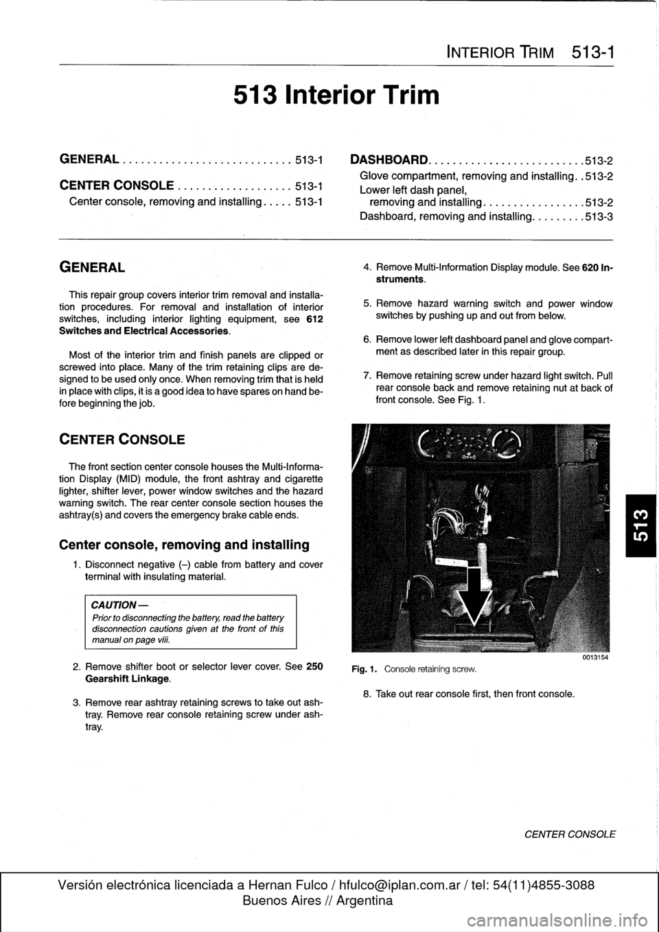
console
.
See
Fig
.
1
.
Fig
.1.
Console
retaining
screw
.
8
.
Take
out
rear
console
first,
then
front
console
.
0013154
CENTER
CONSOLE
Page 347 of 759
Dashboard,
removing
and
installing
1
.
Disconnect
negative
(-)
cable
from
battery
and
cover
terminal
with
insulating
material
.
CAUTION-
Prior
to
disconnectiog
the
battery,
read
the
battery
disconnection
cautionsgiven
at
the
front
of
this
manual
onpage
vi¡¡
.
2
.
Remove
center
console
as
described
earlier
.
3
.
Remove
glove
compartment
as
described
earlier
.
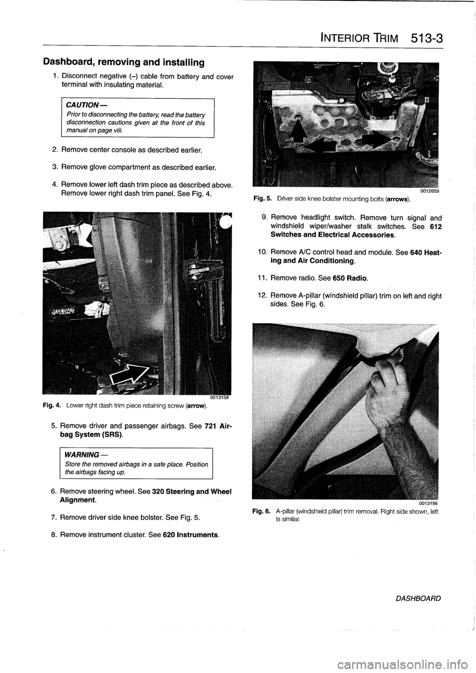
4
.
Remove
lower
left
dash
trim
piece
as
described
above
.
Remove
lower
right
dash
trim
panel
.
See
Fig
.
4
.
Fig
.
4
.
Lower
right
dash
trim
piece
retaining
screw
(arrow)
.
WARNING
-
Store
the
removed
airbags
in
a
safe
place
.
Position
the
airbags
facing
up
.
8
.
Remove
instrument
cluster
.
See
620
Instruments
.
5
.
Remove
driver
and
passenger
airbags
.
See
721
Air-
bag
System
(SRS)
.
6
.
Remove
steering
wheel
.
See
320
Steering
and
Wheel
Alignment
.
INTERIOR
TRIM
513-
3
Fig
.
5
.
Driver
side
knee
bolster
mounting
bolts
(arrows)
.
9
.
Remove
headlight
switch
.
Remove
turn
signal
and
windshield
wiper/washer
stalk
switches
.
See612
Switches
and
Electrical
Accessories
.
10
.
Remove
A/C
control
head
and
module
.
See
640
Heat-ing
and
Air
Conditioning
.
11
.
Remove
radio
.
See650
Radio
.
12
.
Remove
A-pillar
(windshield
pillar)
trim
on
left
and
right
sides
.
See
Fig
.
6
.
UU13156
Fig
.
6
.
A-pillar
(windshield
pillar)
trim
removal
.
Right
side
shown,
left
7
.
Remove
driver
side
knee
bolster
.
See
Fig
.
5
.
is
similar
.
DASHBOARD
Page 348 of 759
513-
4
INTERIOR
TRIM
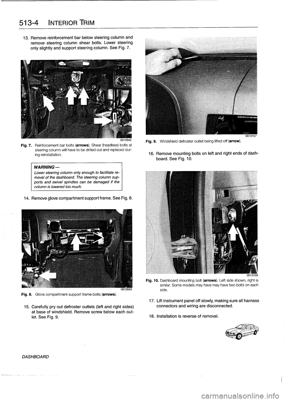
13
.
Remove
reinforcement
bar
below
steering
column
and
remove
steering
column
shear
bolts
.
Lower
steering
only
slightly
and
support
steering
column
.
See
Fig
.
7
.
WARNING
-
Lower
steering
column
only
enough
to
facilitate
re-
moval
of
the
dashboard
.
The
steering
column
sup-
ports
and
swivel
spindles
canbe
damaged
if
the
column
is
lowered
too
much
.
14
.
Remove
glove
compartment
support
frame
.See
Fig
.
8
.
0012643
Fig
.
8
.
Glove
compartment
support
frame
bolts
(arrows)
.
DASHBOARD
0013157
Fig
.
9
.
Windshield
defroster
outlet
being
lifted
off
(arrow)
.
Fig
.
7
.
Reinforcementbar
bolts
(arrows)
.
Shear
(headless)
bolts
at
steering
column
will
have
to
be
drilled
out
and
replaceddur-
ing
reinstallation
.
16
.
Remove
mounting
bolts
on
left
and
right
ends
of
dash-
board
.
See
Fig
.
10
.
Fig
.
10
.
Dashboard
mounting
bolt
(arrows)
.
Left
side
shown,
right
is
similar
.
Some
models
may
have
may
have
two
bolts
oneach
side
.
17
.
Lift
instrument
panel
off
slowly,
making
sure
all
harness
15
.
Carefullypryout
defroster
outlets
(left
and
right
sides)
connectors
and
wiring
are
disconnected
.
a
t
base
of
windshield
.
Remove
screwbelow
each
out-
let
.
See
Fig
.
9
.
18
.
Installation
is
reverse
of
removal
.
Page 379 of 759
Convertible
Top
Lid
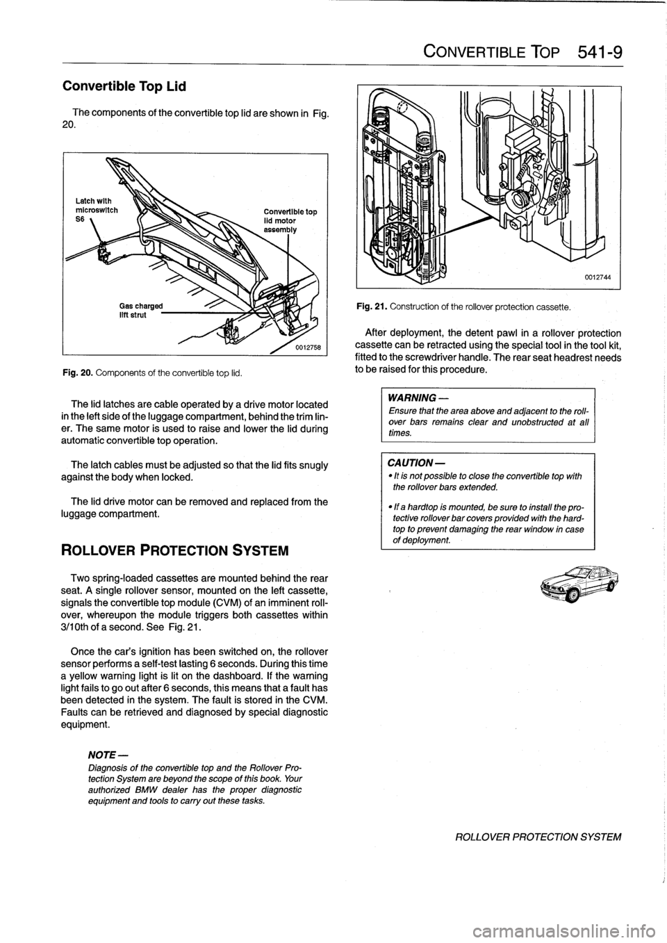
The
components
of
the
convertible
top
lid
are
shown
in
Fig
.
20
.
Fig
.
20
.
Components
of
the
convertible
top
lid
.
ROLLOVER
PROTECTION
SYSTEM
The
lid
latches
are
cable
operated
by
a
drive
motor
located
in
the
left
sideof
the
luggagecompartment,
behind
the
trim
lin-
er
.
The
same
motor
is
used
to
raise
and
lower
the
lid
during
automatic
convertible
topoperation
.
The
latch
cables
must
be
adjusted
so
that
the
lidfits
snugly
against
the
body
when
locked
.
The
lid
drive
motor
can
be
removed
and
replaced
from
the
luggage
compartment
.
Two
spring-locaed
cassettes
are
mounted
behind
the
rear
seat
.
A
single
rollover
sensor,
mounted
on
the
left
cassette,
signals
the
convertible
top
module
(CVM)
of
animminent
roll-
over,
whereupon
the
module
triggers
both
cassettes
within
3j10th
of
a
second
.
See
Fig
.
21
.
Once
the
cars
ignition
has
been
switched
on,
the
rollover
sensor
performs
a
self-test
lasting
6
seconds
.
During
this
time
a
yellow
warning
light
is
lit
on
the
dashboard
.
If
thewarning
lightfails
to
go
out
after
6
seconds,
this
means
that
a
fault
has
been
detected
in
the
system
.
The
fault
is
stored
in
the
CM
Faults
canbe
retrieved
and
diagnosedby
special
diagnostic
equipment
.
NOTE-
Diagnosis
of
the
convertible
top
and
the
Rollover
Pro-
tection
System
are
beyond
the
scope
of
this
book
.
Your
authorized
BMW
dealer
has
the
proper
diagnostic
equipment
and
tools
to
carry
out
these
tasks
.
CONVERTIBLE
TOP
541-
9
Fig
.
21
.
Construction
of
the
rollover
protection
cassette
.
After
deployment,
thedetent
pawl
in
a
rollover
protection
cassette
can
be
retracted
using
the
special
tool
in
the
tool
kit,
fitted
to
the
screwdriver
handle
.
The
rear
seatheadrest
needs
to
be
raised
for
this
procedure
.
WARNING
-
Ensure
that
the
area
above
and
adjacent
to
the
roll-
over
bars
remains
clear
and
unobstructed
at
all
times
.
CAUTION-
"
Itis
not
possible
to
close
the
convertible
top
with
the
rollover
bars
extended
.
"
If
a
hardtop
is
mounted,
be
sure
to
install
the
pro-
tective
rollover
bar
covers
provided
with
the
hard-
top
to
prevent
damaglng
the
rear
window
in
case
of
deployment
.
0012744
ROLLOVER
PROTECTION
SYSTEM
Page 388 of 759
610-2
ELECTRICAL
COMPONENT
LOCATIONS
Fuses
number47
and
50are
mounted
on
the
left
side
splice
panel
.
Refer
lo
Fig
.
5
.
Fuse48
is
mounted
on
the
auxiliary
relay
panel
.
Refer
to
Fig
.
3
.
Fuse
49
is
mounted
in
the
right
side
of
the
luggage
compart-
ment
behind
the
trim
cover
.
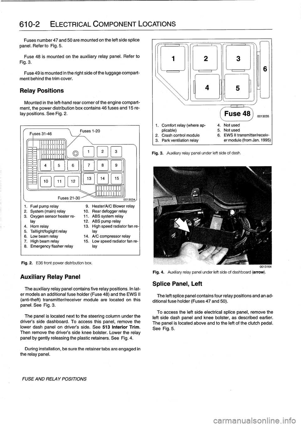
Relay
Positions
Mounted
in
the
left-hand
rear
comer
of
the
engine
compart-
ment,
the
power
distribution
box
contains
46
(uses
and
15
re-
lay
positions
.
See
Fig
.
2
.
Fuses31-46
-
Er
a
&QT
MM
~
Fig
.
2
.
E36
front
power
distribution
box
.
FUSE
AND
RELAY
POSITIONS
Fuses1-20
13
EL1
5
]
mmmmmmmmmm
Fuses
21-30
--
0013034)
1
.
Fuel
pump
relay
9
.
Heater/A/C
Blower
relay
2
.
System
(main)
relay
10
.
Rear
defogger
relay
3
.
Oxygen
sensorheater
re-
11
.
ABS
system
relay
lay
12
.
ABS
pump
relay
4
.
Horn
relay
13
.
High
speed
radiator
fan
re-
5
.
Taillight/foglight
relay
]ay
6
.
Low
beam
relay
14
.
A/C
compressor
relay
7
.
High
beam
relay
15
.
Low
speed
radiator
fan
re-
8
.
Emergency
flasherrelay
¡ay
Auxiliary
Relay
Panel
The
auxiliary
relay
panel
contains
five
relay
positions
.
In
lat-
er
modeis
an
additional
fuse
holder
(Fuse48)
and
the
EWS
II
(anti-theft)
transmitter/receiver
module
are
located
on
this
panel
.
See
Fig
.
3
.
The
panel
is
located
nextto
the
steering
column
under
the
driver's
side
dashboard
.
To
access
this
panel,
remove
the
pwer
dash
panel
on
driver's
side
.
See513
Interior
Trim
.
Then
remove
the
driver's
side
knee
bolster
.
Lower
the
relay
panel
by
gently
releasing
the
plastic
retainers
.
See
Fig
.
4
.
During
installation,
be
sure
the
retainer
tabs
are
engaged
in
the
relay
panel
.
Splice
Panel,
Left
3
¡ni
Fig
.
3
.
Auxiliary
relay
panel
under
left
side
of
dash
.
Fuse
48)
0013035
1
.
Comfort
relay
(where
ap-
4
.
Not
used
plicable)
5
.
Not
used
2
.
Crash
control
module
6
.
EWS
II
transmitter/receiv-
3
.
Park
ventilation
relay
er
module
(from
Jan
.
1995)
0013164
Fig
.
4
.
Auxiliary
relay
panel
under
left
sideof
dashboard
(arrow)
.
The
left
splice
panel
contains
four
relay
positions
and
an
ad-
ditional
fuse
holder
(Fuses
47
and
50)
.
To
access
the
left
side
electrical
splice
panel,
remove
the
left
side
dash
panel
and
knee
bolster,
as
described
earlier
.
The
panel
is
located
above
and
lo
the
left
of
the
clutch
pedal
.
See
Fig
.
5
.
Page 432 of 759
612-4
SWITCHES
AND
ELECTRICAL
ACCESSORIES
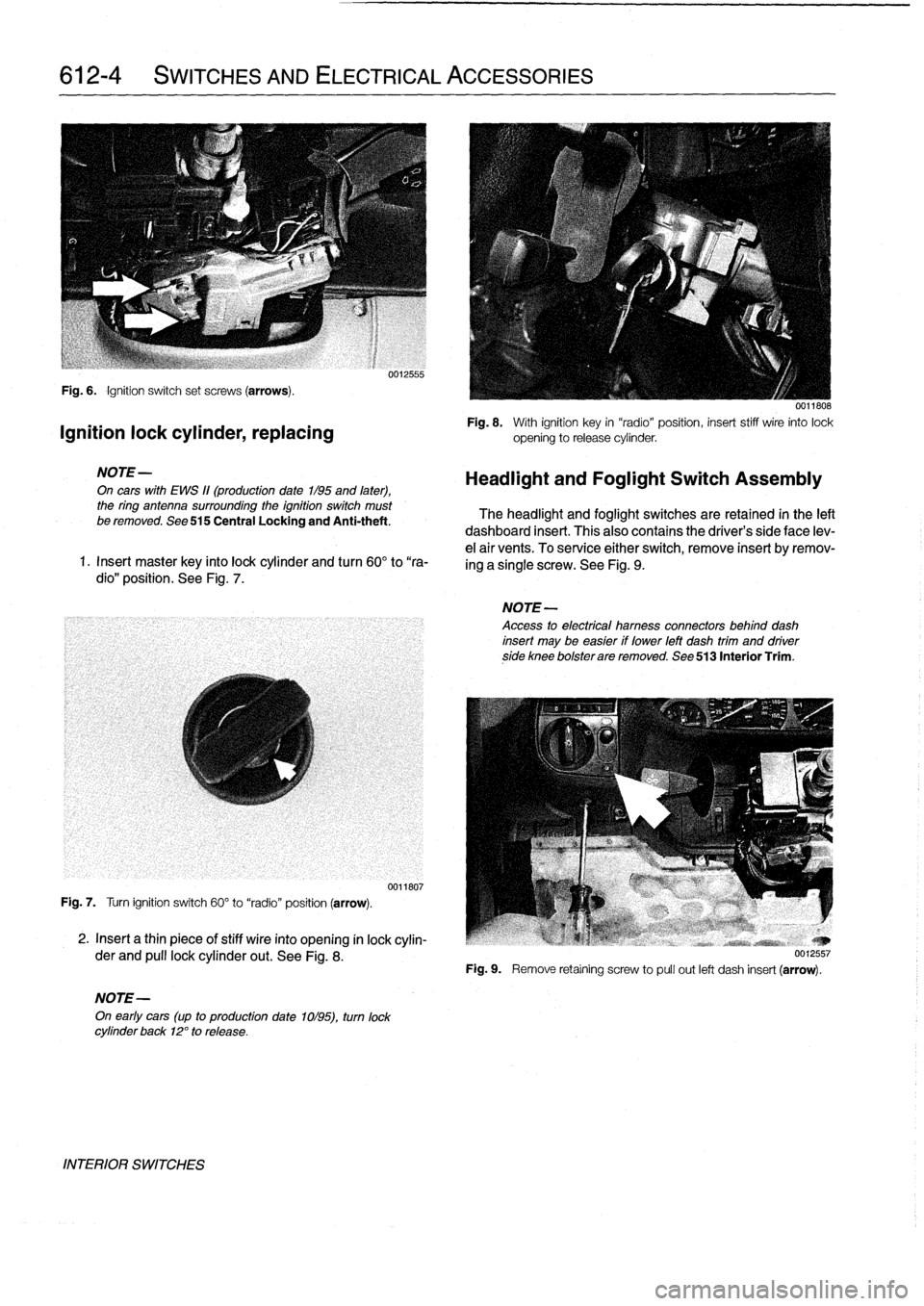
Fig
.
6
.
Ignition
switch
set
screws
(arrows)
.
Ignition
lock
cylinder,
replacing
NOTE-
On
cars
with
EWS
11(production
date
1/95
and
later),
the
ring
antenna
surrounding
the
ignition
switch
must
be
removed
.
See
515
Central
Locking
and
Anti-theft
.
1
.
Insert
master
key
finto
lock
cylinder
and
turn
60°
to
"ra-
dio"
position
.
See
Fig
.
7
.
Fig
.
7
.
Turn
ignition
switch
60°
to
"radio"
position
(arrow)
.
2
.
Insert
a
thin
piece
of
stiff
wire
into
opening
in
lock
cylin-
der
and
pull
lockcylinder
out
.
See
Fig
.
8
.
NOTE-
On
early
cars
(up
to
production
date
1ol95),
turn
lock
cylinder
back
12°
to
release
.
INTERIOR
SWITCHES
0012555
0011807
0011808
Fig
.
8
.
With
ignition
key
in
"radio"position,
insert
stiff
wire
into
lock
opening
to
release
cylinder
.
Headlight
and
Foglight
Switch
Assembly
The
headlight
and
foglight
switches
are
retained
in
the
left
dashboard
insert
.
This
alsocontains
the
driver's
side
face
lev-
e¡
air
vents
.
To
service
either
switch,
remove
insert
byremov-
ing
a
single
screw
.
See
Fig
.
9
.
NOTE-
Access
to
electrical
hamess
connectors
behind
dash
insert
may
be
easier
if
lower
left
dash
trim
and
driverside
knee
bolsterare
removed
.
See
513
Interior
Trim
.
Fig
.
9
.
Remove
retaíning
screw
to
pull
out
left
dash
insert
(arrow)
.
Page 477 of 759
721
Airbag
System
(SRS)
Airbag
Systems
.......
.
...
.
.
.
.
.
....
.
.
.
.
721-1
AIRBAG
SENSORS
AND
ELECTRONICS
721-2
SRS
Warning
Light
and
Fault
Display
.
.
.
.
.
..
721-2
Airbagcontact
ring,
replacing
........
.
.
.
.
.
721-3
Airbag
crash
sensor,replacing
..
.
....
.
...
.
721-4
ZAE
control
module,
replacing
.
.
.
.........
721-5
GENERAL
This
repair
group
covers
only
removal
and
installation
of
air-
bag
components
.
Airbag
system
repair
and
fault
diagnosis
is
not
covered
here
.
Diagnostics,
component
testing,
and
airbag
system
repair
should
be
carried
out
by
trained
BMW
service
technicians
.
NOTE-
Special
test
equipment
is
required
to
retrieve
SRS
fault
codes,
diagnose
system
faults,
and
resetltum
off
the
SRS
indicator
light
.
The
SRS
indicator
light
will
remain
on
until
any
problem
has
been
corrected
and
the
fault
memory
has
been
cleared
.
When
servicing
cars
equipped
with
SRS,
the
precautions
on
this
page
mustbeobserved
to
prevent
personal
injury
.
Airbag
Systems
The
airbag
system
installed
on
E36
cars
through
the
1993
model
year
consisted
of
a
single
airbag
in
the
steering
wheel
.
This
systemcan
be
identified
by
the
orange
crash
sensors
lo-
cated
on
the
front
wheel
wells
and
the
absence
of
a
passenger
side
airbag
.
The
ZAE
airbag
system,
starting
in
model
year
1994
(pro-
duction
date9/93
and
later),
provides
both
a
driver
side
and
a
passenger
sideairbag
.
On
ZAE
vehicles,
the
crash
sensorsare
integrated
into
the
airbag
control
module,
located
under
thecenter
of
the
rear
seat
.
The
ZAE
control
module
triggers
deployment
of
the
airbags
When
it
sensos
the
vehicle
deceler-
ating
at
a
rate
equivalent
to
a
head-on
collisionof
at
least
13
mph
(18
km/h)
.
In
some
1997
4-door
models
and
all
1998
models,
side-impact
airbags
were
installed
in
the
front
doors
.
The
airbag
units
are
mounted
behindthe
door
trim
panels
.
Caution
mustbeused
when
working
on
vehicle
systems
in
the
proximity
of
air
bags,
such
as
the
steering
column,
the
dashboard,
or
the
doors
.
AIRBAG
SYSTEM
(SRS)
721-1
GENERAL
.
.
.
.
.
.
.
.
.
.
.......
.
......
.
.
.
.
721-1
Front
side-impact
airbag
crash
sensor,
removing
and
installing
....
.
.....
.
.....
.
721-5
AIRBAGS
..............
.
.
.
.
.
.
.
.
.
.
.
.
.
.
.
721-5
Driver
side
airbag,
removing
and
installing
.
.
.
721-5
Passenger
side
airbag,
removing
and
installing
..............
.
.
.721-6
Front
side-impact
airbag,
removing
and
installing
.
.
.
.
.
.
.
.
.
.
......
.721-7
WARNING
-
"
Airbag(s)
are
inflated
byan
explosive
device
.
Handled
improperly
or
without
adequate
safe-
guards,
the
System
can
be
very
dangerous
.
Spe-
cial
precautions
must
be
observed
prior
to
any
work
ator
near
the
driverside
airbag,
the
passen-
ger
side
airbag
(where
applicable)
or
the
side-im-
pact
airbags
(where
applicable)
.
"
The
airbag
is
a
vehicle
safety
system
.
Serious
in-
jury
may
result
if
System
service
is
attempted
by
persons
unfamiliar
with
the
BMW
SRS
and
its
ap-
proved
service
procedures
.
BMW
advises
that
all
inspection
and
service
be
performed
by
an
autho-
rized
BMW
dealer
.
"
Always
disconnect
the
battery
and
cover
the
neg-
ative
()
battery
terminal
with
an
insulator
before
startingdiagnostic,
troubleshooting
or
service
worknot
associated
with
SRS,
and
before
doing
any
welding
on
the
car
.
"
If
an
airbag
has
been
activated
due
to
an
acci-dent,
BMW
specifies
that
SRS
components
be
replaced
.
For
more
information
on
post-collision
SRS
service,
see
an
authorized
BMW
dealer
.
"
Do
not
allow
the
airbag
unit
to
come
in
contact
with
cleaning
solutions
orgrease
.
Never
subject
an
airbag
unit
to
temperatures
aboye
212°F
(100°C)
.
When
reconnecting
the
battery,
no
per-
son
should
be
inside
the
vehicle
.
"
Always
place
an
airbag
unitthat
has
been
re-
moved
from
its
packaging
with
the
padded
sidefacing
upward
.
Do
not
leave
an
airbag
unlt
unat-
tended
.
"
!f
the
airbag
unit
or
airbag
control
modulehas
been
dropped
froma
height
of
!
1
2
meter
(1
Y2
ft.)
ormore,
theairbag
unit
should
not
be
installed
.
Aírbag
system
components
are
shown
in
Fig
.
1.
GENERAL