light BMW 325i 1994 E36 Owner's Guide
[x] Cancel search | Manufacturer: BMW, Model Year: 1994, Model line: 325i, Model: BMW 325i 1994 E36Pages: 759
Page 79 of 759
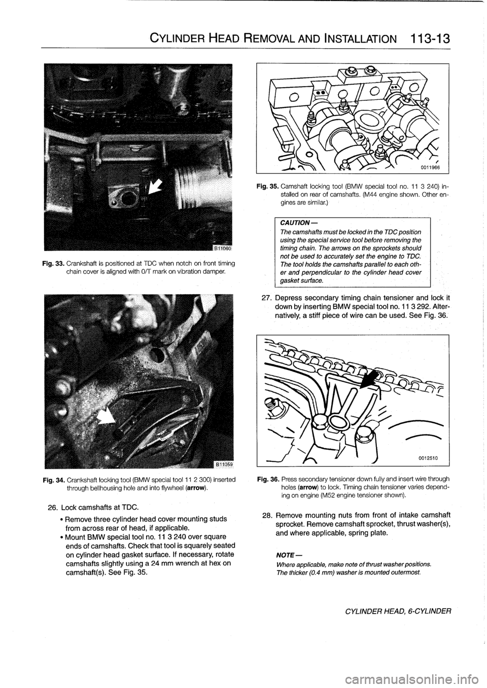
Fig
.
33
.
Crankshaft
is
positioned
at
TDC
when
notch
oh
front
timing
chain
cover
is
alignedwith
0/T
mark
on
víbration
damper
.
CYLINDER
HEAD
REMOVAL
AND
INSTALLATION
113-
1
3
Fig
.
35
.
Camshaft
locking
tool
(BMW
special
tool
no
.
11
3
240)
in-
stalled
on
rear
of
camshafts
.
(M44
engine
shown
.
Other
en-
gines
are
similar
.)
CAUTION-
The
camshafts
must
be
locked
in
the
TDC
position
using
the
special
service
tool
before
removing
the
timing
chain
.
Thearrowson
the
sprockets
should
not
be
used
to
accurately
set
the
engine
to
TDC
.
The
tool
holds
the
camshafts
parallel
to
each
oth-
er
and
perpendicular
to
the
cylinder
head
covergasket
surface
.
27
.
Depress
secondary
timing
chain
tensioner
and
lock
t
down
by
inserting
BMW
special
tool
no
.
113
292
.
Alter-
natively,
a
stiff
piece
of
wire
can
be
used
.
See
Fig
.,36
.
Fig
.
34
.
Crankshaft
locking
tool
(BMW
special
tool
11
2
300)
inserted
Fig
.
36
.
Press
secondary
tensioner
down
fully
and
insert
wire
through
through
bellhousinghole
and
finto
flywheel
(arrow)
.
holes
(arrow)
to
lock
.
Timingchain
tensioner
varies
depend-
ing
on
engine
(M52
engine
tensioner
shown)
.
26
.
Lockcamshafts
at
TDC
.
"
Remove
three
cylinder
head
cover
mounting
studs
28
.
Remove
mounting
nuts
from
front
of
intake
camshaft
from
across
rear
of
head,
if
applicable
.
sprocket
.
Remove
camshaft
sprocket,
thrust
washer(s),
"
Mount
BMW
special
tool
no
.
11
3
240
over
square
and
where
applicable,
spring
plate
.
ends
of
camshafts
.
Check
that
tool
is
squarely
seated
on
cylinder
head
gasket
surface
.
If
necessary,
rotate
NOTE-
camshafts
slightly
using
a
24
mm
wrench
at
hexon
Where
applicable,
make
note
of
thrust
washer
positions
.
camshaft(s)
.
See
Fig
.
35
.
The
thicker
(0
.4
mm)
washer
is
mounted
outermost
.
CYLINDER
HEAD,6-CYLINDER
Page 81 of 759
NOTE-
Cylinder
head,
installing
(6-cylinder
engine)
CAUTION-
If
the
camshafts
were
removed
and
installed
while
the
cylinder
head
was
off,
a
minimum
waiting
time
is
required
after
ínstalling
the
camshafts
.
When
the
camshaftsareremoved,
the
hydraullc
lifters
can
expand
.
This
expansion
can
cause
increased
valve
lift
when
the
camshafts
are
bolted
down,
re-
sulting
in
open
valves
.
Cylinder
head
installation
waiting
times
"
68°F
(20°C)
and
higher
.
.
.
..
..........
10
minutes
"
50-68°F
(10-20°C)
........
..
.........
30
minutes
"
32-50°F
(0-10
°C)
.........
...
........
75
minutes
CYLINDER
HEAD
REMOVAL
AND
INSTALLATION
113-
1
5
1
.
Clean
cylinder
head
and
gasket
surfaces
of
cylinder
block
and
al¡
timing
chain
covers
.
"
Remove
all
foreign
matter
and
any
¡¡quid
from
bolt
holes,
then
clean
with
a
thread
chaser
.
CA
UTION-
Do
not
use
ametal
scraper
or
wire
brush
to
clean
the
aluminum
cylinder
head
or
pistons
.
If
neces-
sary,
use
a
hard
wooden
or
plastic
scraper
.
Also
available
are
abrasive
discs
to
be
used
in
conjunc-
tion
with
an
electric
drill
.
Be
sure
to
use
the
correct
disc
for
the
typeof
metal
being
cleaned
.
2
.
Check
gasket
surface
of
cylinder
head
and
cylinder
block
for
warpage
using
a
straight
edge
.
NOTE-
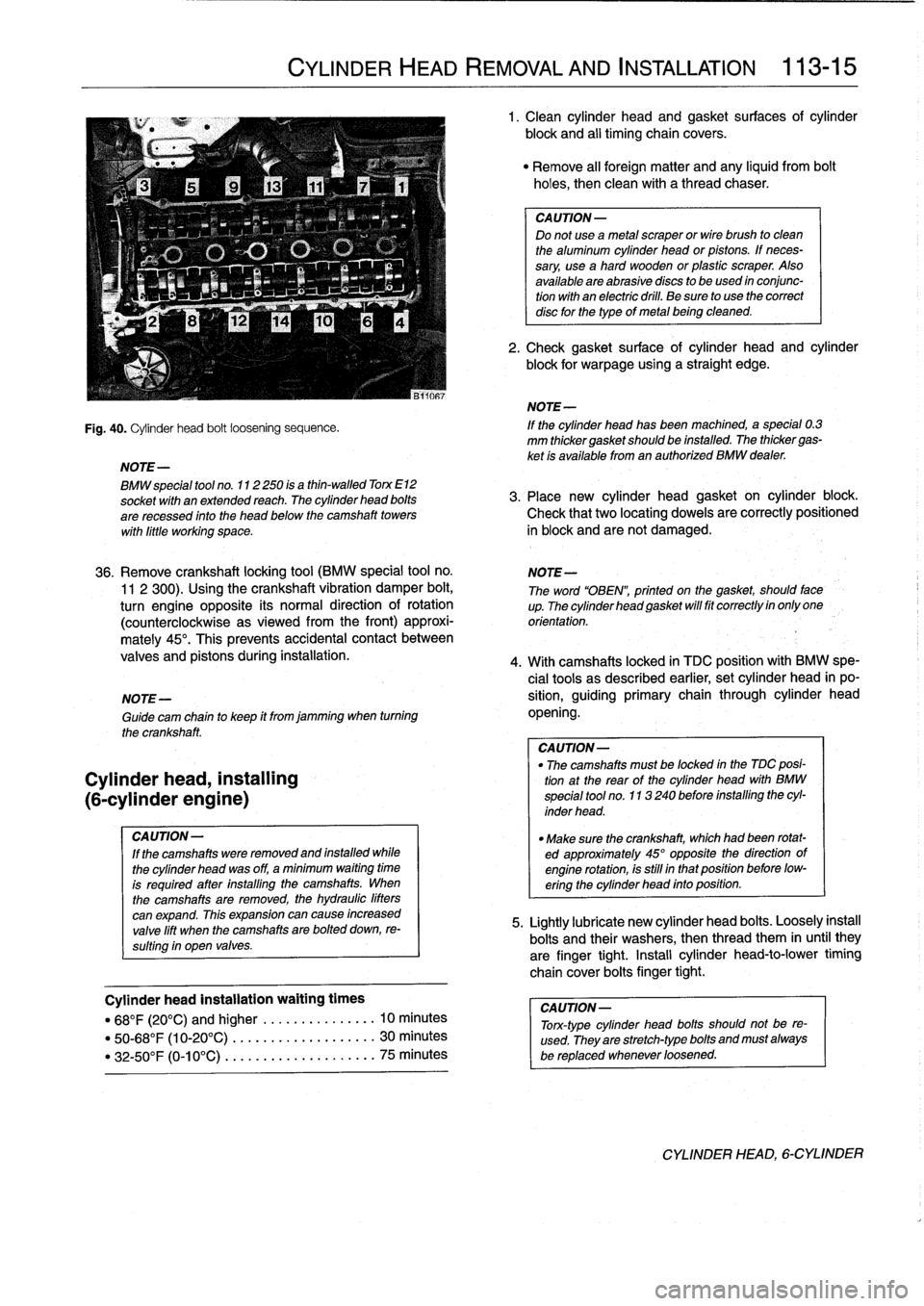
Fig
.
40
.
Cylinder
head
bolt
loosening
sequence
.
If
the
cylinder
head
has
been
machined,a
special
0
.3
mm
thickergasketshould
be
installed
.
The
thickergas-
ket
is
available
from
an
authorized
BMW
dealer
.
BMW
special
tool
no
.
112250
is
a
thin-walled
Torx
E12
socket
wíth
anextended
reach
.
The
cylinder
head
bolts
3
.
Place
new
cylinder
head
gasket
on
cylinder
block
.
are
recessed
finto
the
head
below
the
camshaft
towers
Check
that
two
locating
dowels
are
correctly
positioned
wíth
liffle
working
space
.
in
block
and
arenot
damaged
.
36
.
Remove
crankshaft
locking
tool
(BMW
special
tool
no
.
NOTE-
11
2
300)
.
Using
the
crankshaft
vibration
damper
bolt,
The
word
"OBEN",
printed
on
the
gasket,
should
face
turn
engine
opposite
its
normal
direction
of
rotation
up
.Thecylinderheadgasketwillfitcorrectlyinonlyone
(counterclockwise
asviewed
from
the
front)
approxi-
orientation
.
mately
45°
.
This
prevents
accidental
contact
between
valves
and
pistons
during
installation
.
4
.
With
camshafts
locked
in
TDC
positionwith
BMW
spe-
cial
tools
as
described
earlier,
set
cylinder
head
in
po
NOTE-
sition,
guiding
primary
chain
through
cylinder
head
Guide
cam
chain
to
keep
it
from
jamming
when
turning
opening
.
the
crankshaft
.
CA
UTION-
"
The
camshafts
must
be
locked
in
the
MC
posi-
tion
at
the
rear
of
the
cylinder
head
with
BMW
special
tool
no
.
113240
before
installing
the
cyl-
inder
head
.
"
Make
sure
the
crankshaft,
which
had
been
rotat-
ed
approximately
45°
opposite
thedirection
of
engine
rotation,is
still
in
that
position
before
low-
ering
the
cylinder
head
into
position
.
5
.
Lightly
lubricate
new
cylinder
head
bolts
.
Loosely
instan
bolts
and
their
washers,
then
thread
them
in
until
they
are
finger
tight
.
Install
cylinder
head-to-lower
timing
chaincover
boitsfinger
tight
.
CAUTION-
Tonc-type
cylinder
head
bolts
should
not
be
re-
used
.
They
are
stretch-typebolts
and
must
always
be
replaced
whenever
loosened
.
CYLINDER
HEAD,
6-CYLINDER
Page 99 of 759
NOTE-
The
vibration
damper
center
bolt
is
very
tight
.
A
heavy
duty
holding
device,
such
as
BMW
special
tool
no
.
112
150,
should
be
used
to
hold
the
vibration
damper
hub
V
stationary
while
the
bolt
is
loosened
.
v
11
.
Usingloosened
bolt
at
vibration
damper,
turn
crank-
shaft
to
TDC
and
lock
in
position
by
inserting
BMW
special
tool
no
.
11
2
300
through
transmission
bell-
-
p
housing
.
See
Fig
.
5
.
v
O
NOTE-
I\
0011966a
"
If
necessary,
remove
plugfrom
locating
boye
in
lower
edge
of
bell
housing
.
"
Confirm
that
locatng
tool
has
been
correctlyinstalled
by
trying
to
rotate
the
crankshaft
.
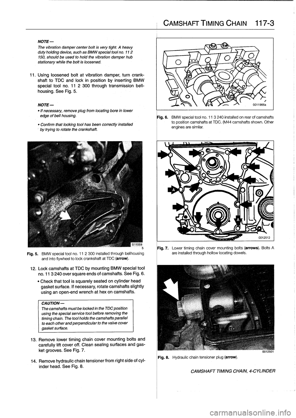
Fig
.
7
.
Lower
timing
chain
cover
mounting
bolts
(arrows)
.
Bolts
A
Fig
.
5
.
BMW
special
tool
no
.
11
2300
installed
through
bellhousing
are
installed
through
hollow
locating
dowels
.
and
finto
flywheel
to
lock
crankshaft
at
TDC
(arrow)
.
CA
UTION-
Thecamshafts
mustbe
locked
in
the
MC
position
using
the
specialservice
tool
before
removing
the
timing
chain
.
The
tool
holds
the
camshafts
parallel
to
each
other
and
perpendicular
to
the
valve
cover
gasket
surface
.
12
.
Lockcamshafts
at
TDC
bymounting
BMW
special
tool
no
.
113
240
over
square
ends
of
camshafts
.
See
Fig
.
6
.
"
Check
that
tool
is
squarely
seated
on
cylinder
head
gasket
surface
.
If
necessary,
rotate
camshafts
slightly
using
an
open-end
wrench
at
hexon
camshafts
.
13
.
Remove
lower
timing
chaincover
mounting
bolts
and
carefully
lift
cover
off
.
Clean
sealing
surfaces
and
gas-
ket
grooves
.
See
Fig
.
7
.
14
.
Remove
hydraulic
chaintensioner
from
right
side
of
cyl-
inder
head
.
See
Fig
.
8
.
CAMSHAFT
TIMING
CHAIN
117-
3
Fig
.
6
.
BMW
special
tool
no
.
11
3240
installed
on
rearof
camshafts
to
position
camshafts
at
TDC
.
(M44
camshafts
shown
.
Other
engines
are
similar
.
Fig
.
8
.
Hydraulic
chain
tensionerplug
(arrow)
.
CAMSHAFT
TIMING
CHAIN,
4-CYLINDER
Page 102 of 759
117-
6
CAMSHAFT
TIMING
CHAIN
15
.
Insta¡¡
upper
timing
chaincover
:
17
.
Remove
crankshaft
locking
tool
from
transmission
bell-
"
Thoroughly
clean
profile
gasketgroove
and
all
sealing
housing
and
camshaft
locking
tool
from
rear
of
cylinder
surfaces
.
head
.
"
Applya
small
bead
ofsilicon
sealer
(3-Bond
1209®
or
equivalent)
to
upper
and
lower
joint
comers
where
18
.
Turn
engine
over
by
hand
in
direction
of
rotation
at
least
chaincover
meets
cylinder
head
.
two
full
rotations
.
Reinstall
camshaft
and
crankshaft
"
Insta¡¡
new
profile
gasket
to
groove
in
lowerchain
cover
.
locking
tools
to
check
engine
timing
.
Repeat
cam
timing
"
Protect
top
of
profile
gasket
using
thin
sheetmetal
procedure
if
tools
do
not
fit
easily
into
position
.
Remove
(BMW
special
tool
no
.
11
2
330
or
equivalent)
.
See
locking
tools
.
Fig
.
15
.
"
Attach
new
gaskets
to
cover
with
light
dabs
of
gasket
19
.
Install
cylinder
head
cover
as
described
in
113
Cylin-
sealant,
hold
gaskets
in
placeusing
cover
mounting
der
HeadRemoval
and
Installation
.
screws
.
"
Place
upper
timing
cover
into
position
.
Snug
down
al¡
NOTE-
screws,
without
tightening
.
Carefully
slide
out
sheet
OnM44
engines,
note
oil
supply
O-ring
and
replace
ff
metal
.
necessary
.
"
Temporarily
install
cylinder
head
cover
without
gasket
.
Insta¡¡
and
tighten
at
least
two
cylinder
head
cover
mounting
bolts
to
seat
upper
timing
chaincover
.
"
Tighten
all
upper
timing
cover
screws
.
Tightening
Torque
"
Remove
valve
cover
.
"
Cylinder
head
cover
to
cylinder
head
(M6
screws)
...
..
.
.
10
Nm
(89
ín-Ib)
-
CAMSHAFT
TIMING
CHAINS,
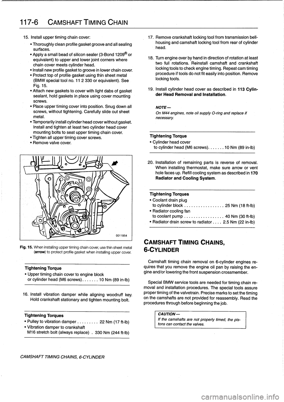
Fig
.
15
.
When
installing
upper
timing
chain
cover,
use
thin
sheetmetal
6-CYLINDER
(arrow)
to
protect
profile
gasket
when
installing
uppercover
.
Tightening
Torque
"
Upper
timing
chaincover
to
engine
block
or
cylinder
head
(M6
screws)
....
.
..
10
Nm
(89
in-lb)
16
.
Install
vibration
damper
while
aligning
woodruff
key
.
Hold
crankshaft
stationary
and
tighten
mounting
bolt
.
Tightening
Torques
I
CAUTION-
"
Pulley
to
vibration
damper
..
.
.
.
....
22
Nm
(17
ft-Ib)
lf
the
camshaftsare
not
properly
timed,
the
1
pis-
tons
can
contact
thevalves
.
"
Vibration
damper
tocrankshaft
M16
stretch
bolt
(always
replace)
.
330
Nm
(244
ft-Ib)
CAMSHAFT
TIMINGCHAINS,
6-CYLINDER
20
.
Installation
of
remaining
parts
is
reverse
of
removal
.
When
installing
thermostat,
make
sure
arrow
or
vent
hole
faces
up
.
Refill
cooling
system
as
described
in
170
Radiator
and
Cooling
System
.
Tighteníng
Torques
"
Coolant
drain
plug
to
cylinder
block
.
..
.
.
.
...
.
..
.....
25
Nm
(18
ft-Ib)
"
Radiator
cooling
fan
to
coolant
pump
.
..
.
...
...
..
.....
40
Nm
(30
ft-Ib)
"
Radiator
drain
screw
to
radiator
....
2
.5
Nm
(22
in-lb)
Camshaft
timing
chainremovalon
6-cylinder
engines
re-
quires
that
you
Rmove
the
engine
oil
pan
by
raising
the
en-
gine
and/or
lowering
the
front
suspension
crossmember
.
Special
BMW
service
tools
are
needed
for
timing
chain
re-
moval
and
installation
procedures
.
The
special
tools
assure
proper
timing
of
the
valvetrain
.
Precise
marks
to
setthe
timing
on
the
camshafts
arenot
provided
for
reassembly
.
Read
the
procedures
through
before
beginning
thejob
.
Page 105 of 759
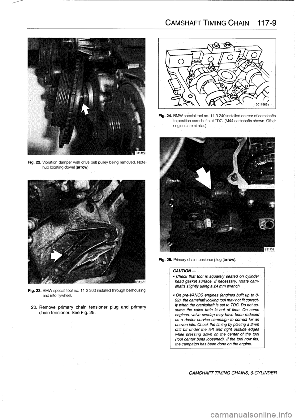
Fig
.
22
.
Vibration
damper
with
drive
belt
pulley
being
removed
.
Notehub
locating
dowel
(arrow)
.
Fig
.
23
.
BMW
special
tool
no
.
11
2
300
installed
through
bellhousing
and
into
flywheel
.
20
.
Remove
primary
chain
tensioner
plug
and
primary
chain
tensioner
.
See
Fig
.
25
.
CAMSHAFT
TIMING
CHAIN
117-
9
Fig
.
24
.
BMW
special
tool
no
.
113
240
installed
on
rear
of
camshafts
to
position
camshafts
at
TDC
.
(M44
camshafts
shown
.
Other
engines
are
similar
.)
Fig
.
25
.
Primary
chain
tensioner
plug
(arrow)
.
CAUTION-
"
Check
thattool
is
squarely
seated
on
cytinder
head
gasket
surface
.
If
necessary,
rotate
cam-
shafts
slightly
using
a
24
mm
wrench
"
On
pre-VANOS
engines
(engines
built
up
to
8-
92),
the
camshaft
locking
tool
may
not
fit
correct-
ly
when
the
crankshaft
is
set
to
TDC
.
Do
notas-
sume
the
valve
train
is
out
oftime
.
On
some
engines,
valve
overlap
may
havebeen
reduced
as
a
dealer
service
campaign
to
correct
for
an
uneven
idle
.
Check
thetiming
by
placing
a
3mm
drill
bit
under
the
left
and
right
outside
edges
while
pressíng
down
on
thecenter
of
the
tool
(tool
center
bolts
loosened)
.
If
the
tool
now
fits,
the
campaign
has
beendone
on
the
engine
.
CAMSHAFT
TIMING
CHAINS,
6-CYLINDER
Page 106 of 759
117-
1
0
CAMSHAFT
TIMING
CHAIN
21
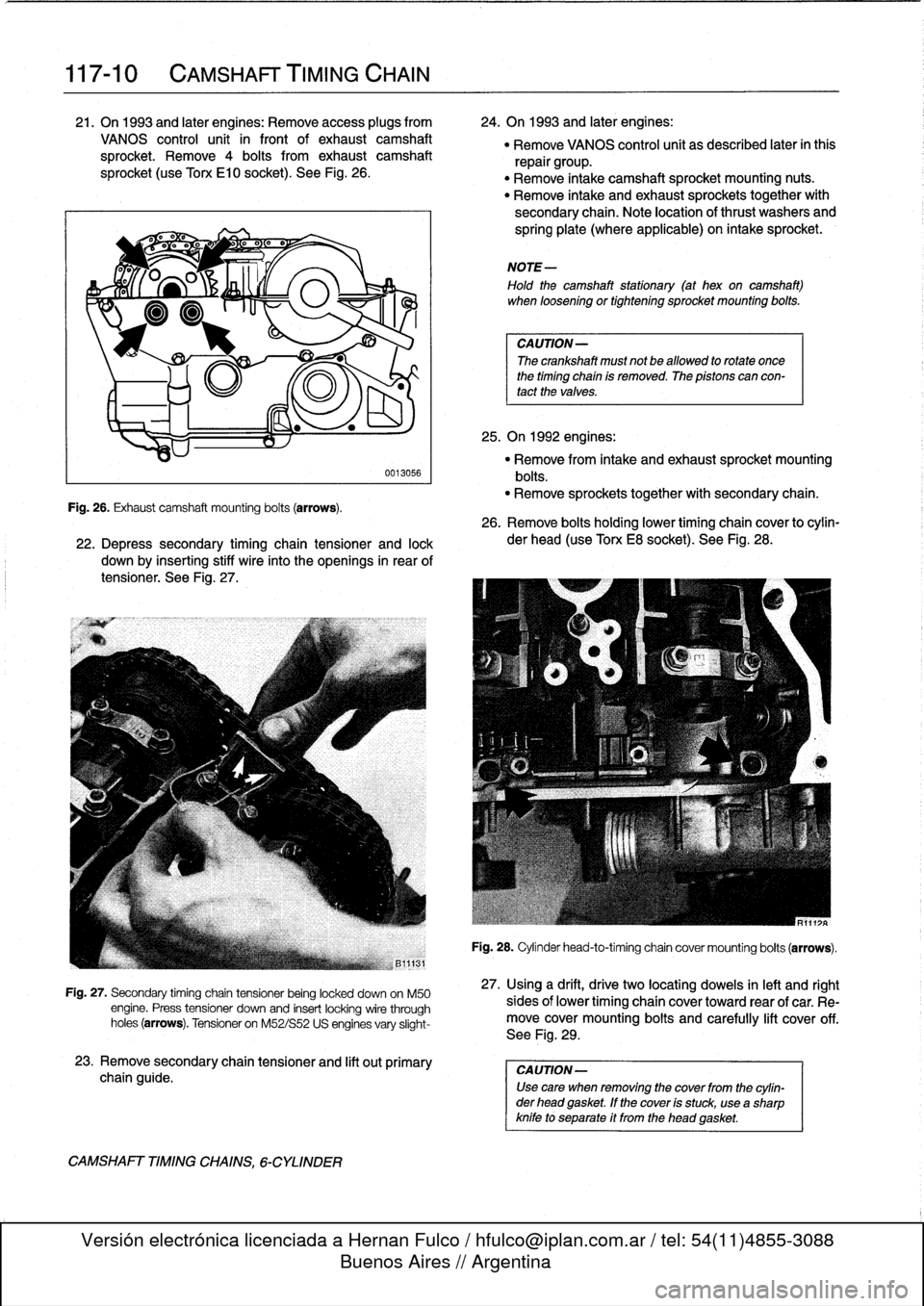
.
On
1993
and
lates
engines
:
Remove
access
plugs
from
24
.
On
1993
and
later
engines
:
VANOS
control
unit
in
front
of
exhaust
camshaft
"
Remove
VANOS
control
unit
as
described
laterinthis
sprocket
.
Remove
4
bolts
from
exhaust
camshaft
repair
group
.
sprocket
(useTono
El0
socket)
.
See
Fig
.
26
.
"
Remove
intake
camshaft
sprocket
mounting
nuts
.
"
Remove
intake
and
exhaust
sprockets
together
with
secondary
chain
.
Note
location
of
thrust
washers
and
spring
plate
(where
applicable)
on
intake
sprocket
.
Fig
.
26
.
Exhaust
camshaftmounting
bolts
(arrows)
.
CAMSHAFT
TIMING
CHAINS,
6-CYLINDER
0013056
22
.
Depress
secondary
timing
chain
tensiones
and
lock
down
by
inserting
stiff
wire
into
the
openings
in
rear
of
tensioner
.
See
Fig
.
27
.
Fig
.
27
.
Secondary
timing
chaintensioner
being
locked
down
on
M50
engine
.
Press
tensioner
downand
insert
locking
wire
through
holes(arrows)
.
Tensioner
on
M52/S52
US
engines
vary
slight-
23
.
Remove
secondary
chain
tensioner
and
lift
out
primary
chain
guide
.
NOTE-
Hold
the
camshaft
stationary
(at
hex
on
camshaft)
when
loosening
ortightening
sprocket
mounting
boits
.
CAUTION-
The
crankshaft
must
not
be
allowed
to
rotate
once
the
timing
chain
is
removed
.
The
pistons
can
con-
tact
the
valves
.
25
.
On
1992
engines
:
"
Remove
from
intake
and
exhaust
sprocket
mounting
bolts
.
"
Remove
sprockets
together
with
secondary
chain
.
26
.
Remove
bolts
holding
lower
timing
chain
cover
to
cylin-
der
head
(use
Torx
E8
socket)
.
See
Fig
.
28
.
MR111:
R
Fig
.
28
.
Cylinderhead-to-timingchain
covermounting
bolts
(arrows)
.
27
.
Using
a
drift,
drive
two
locatiog
dowels
in
left
and
right
sides
of
lower
timing
chaincover
toward
rear
of
car
.
Re-
move
covermounting
boits
and
carefully
lift
cover
off
.
See
Fig
.
29
.
CA
UTION-
Use
care
when
removing
the
cover
from
the
cylin-
der
head
gasket
.
If
the
cover
is
stuck,
useasharp
knife
to
separate
it
from
the
head
gasket
.
Page 107 of 759
9)
B11126
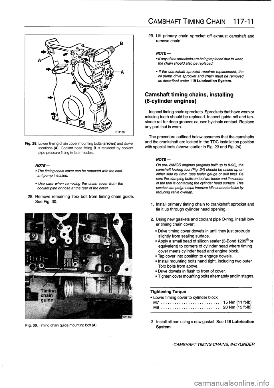
Fig
.
29
.
Lower
timing
chain
cover
mounting
bolts
(arrows)
anddowel
locations
(A)
.
Coolant
hose
fitting
B
is
replaced
by
coolant
pipe
pressure
fitting
in
later
models
.
28
.
Remove
remaining
Torx
bolt
from
timing
chain
guide
.
See
Fig
.
30
.
Fig
.
30
.
Timing
chainguide
mounting
bolt(A)
.
CAMSHAFT
TIMING
CHAIN
117-
11
29
.
Lift
primary
chain
sprocket
off
exhaust
camshaft
and
remove
chain
.
NOTE-
"
If
any
of
the
sprockets
are
being
replaced
due
to
wear,
the
chain
should
also
be
replaced
.
"
If
the
crankshaft
sprocket
requires
replacement,
the
oil
pump
drive
sprocket
and
chain
must
be
removed
as
described
under
119
Lubrication
System
.
Camshaft
timing
chains,
installing
(6-cylinder
engines)
Inspecttiming
chainsprockets
.
Sprockets
that
haveworn
or
missing
teeth
should
be
replaced
.
Inspect
guide
rail
and
ten-
sioner
rail
for
deep
grooves
caused
by
chain
contact
.
Replace
any
parí
that
is
worn
.
The
procedure
outlined
below
assumes
that
the
camshafts
and
the
crankshaft
are
locked
in
the
TDC
installation
position
with
special
tools
(shown
earlier
in
Fig
.
23
and
Fig
.
24)
.
NOTE-
NOTE-
On
pre-VANOS
engines
(engines
built
up
to
8-92),
the
"
The
timing
chain
cover
can
be
removed
with
the
cool-
camshaft
locking
tool
(Fig
.
24)should
be
raised
upon
ant
pump
installed
.
eitherside
by
3mm
(use
feeler
gauge
or
dril¡
bits)
.
Be
sure
the
clamping
bolts
on
tool
are
loose
and
thecenter
"
Use
care
when
removing
the
chain
cover
from
the
of
the
tool
is
contacting
the
cylinder
head
surface
.
This
coolant
pipe
or
hose
at
the
rearof
the
cover
.
service
campaign
helps
improve
idle
characteristics
by
reducing
valve
overlap
.
1
.
Install
primary
timing
chain
to
crankshaft
sprocket
and
tie
it
up
through
cylinder
head
opening
.
2
.
Using
new
gaskets
and
coolant
pipe
O-ring
;
insta¡¡
low-
ertiming
chain
cover
:
"
Drive
timing
cover
doweis
inuntil
they
just
protrude
slightly
from
sealing
surface
.
"
Apply
a
small
bead
of
silicon
sealer
(3-Bond
1209
©
or
equivalent)
to
corners
of
cylinder
head
where
timing
cover
meets
cylinder
head
and
engine
block
.
"
Tap
cover
into
position
to
engage
doweis
.
"
Install
mounting
bolts
hand
tight,
including
two
outer
Torx
bolts
from
above
.
"
Drive
doweis
in
flush
to
front
of
cover
.
"
Tighten
cover
mounting
bolts
alternately
and
in
stages
.
Tightening
Torque
"
Lower
timing
cover
to
cylinder
block
M7
................
...
..
.
.....
15
Nm
(11
ft-Ib)
M8
.............
.
.
...
.........
20
Nm
(15
ft-Ib)
3
.
Insta¡¡
oil
pan
using
a
new
gasket
.
See
119
Lubrication
Systern
.
CAMSHAFT
TIMINGCHAINS,
6-CYLINDER
Page 112 of 759
117-
1
6
CAMSHAFT
TIMING
CHAIN
15
.
Remove
crankshaft
locking
tool
.
Remove
special
test
equipment
.
Insta¡¡
oil
supply
line
using
new
seals
and
reconnect
solenoid
connector
.
Remainder
of
installa-
tion
is
reverse
of
removal
.
Tightening
Torque
"
Cylinder
head
cover
to
cylinder
head
.
10
Nm
(89
in-lb)
"
VANOS
oil
supply
line
to
VANOS
control
unit
(banjo
bolt)
..
.........
32
Nm
(24
ft-Ib)
"
VANOS
solenoidlo
VANOS
control
unit
........
.
.
.
..
........
30
Nm
(22
ft-Ib)
VANOS
control
unit,
removing
Special
BMW
service
tools
are
required
lo
remove
and
in-
stall
the
VANOS
control
unit
.
Read
the
procedure
through
be-
forestarting
the
job
.
1
.
Remove
radiator
cooling
fan
shroud
and
cooling
fan
.
See
170
Radiator
and
Cooling
System
.
CAUTION-
Radiator
fan
has
left
hand
threads
.
2
.
Remove
top
plastic
engine
covers
.
Disconnect
ignition
coil
harness
connectors
from
coils
.
Remove
ignition
coils
.
Remove
cylinder
head
cover
.
Unclip
andremove
oil
baffle
cover
from
above
intake
camshaft
.See
113
Cylinder
Head
Removal
and
Installation
.
NOTE-
Make
note
of
the
mounting
bolt
insulator
arrangement
during
removal
of
the
cylinder
head
cover
.
3
.
Set
engine
lo
TDC
by
rotating
engine
in
normal
operat-
ing
direction
until
camshaft
lobes
at
cylinder
no
.
1
are
facing
each
other
and
"0/T"
mark
(0°TDC)
on
vibration
damper
lines
up
with
cast
boss
on
lower
timing
chain
cover
.
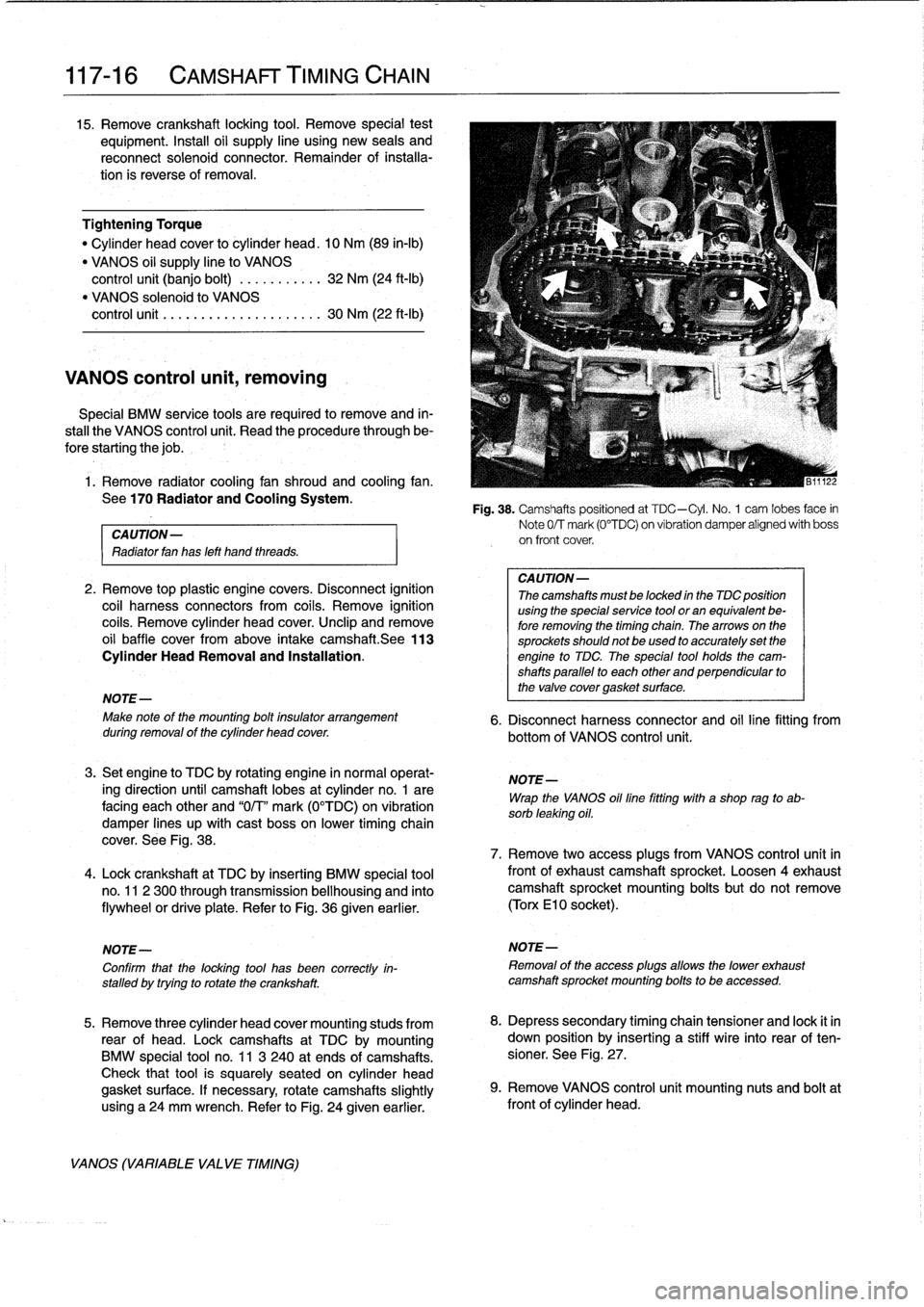
See
Fig
.
38
.
4
.
Lock
crankshaft
at
TDC
by
inserting
BMW
special
tool
no
.
11
2
300
through
transmission
bellhousing
and
finto
flywheel
or
drive
plate
.
Refer
to
Fig
.
36
given
earlier
.
NOTE-
Confirm
that
the
locking
tool
has
been
correctly
in-
stalled
by
trying
to
rotatethe
crankshaft
.
5
.
Remove
three
cylinder
head
cover
mounting
studs
from
rear
of
head
.
Lockcamshafts
at
TDC
bymounting
BMW
special
tool
no
.
11
3
240
at
ends
of
camshafts
.
Check
that
tool
is
squarely
seated
on
cylinder
head
gasket
surface
.
If
necessary,
rotate
camshafts
slightly
using
a24
mm
wrench
.
Refer
to
Fig
.
24
given
earlier
.
VANOS
(VARIABLE
VALVE
TIMING)
Fig
.
38
.
Camshafts
positioned
at
TDC-Cyl
.
No
.
1
cam
lobes
face
in
Note
0/T
mark
(0°TDC)
on
vibration
damper
alígned
with
boss
on
front
cover
.
CA
UTION-
Thecamshafts
mustbe
locked
in
the
TDC
position
using
the
specialservice
tool
or
an
equivalent
be-
fore
removing
the
timing
chain
.
Thearrows
on
the
sprockets
should
not
be
used
to
accurately
set
the
engine
to
TDC
The
special
tool
holds
the
cam-
shafts
parallel
to
each
other
and
perpendicular
to
the
valve
cover
gasket
surface
.
6
.
Disconnect
harness
connector
and
oil
line
fitting
from
bottom
of
VANOS
control
unit
.
NOTE-
Wrap
the
VANOS
oilfine
fitting
with
a
shop
rag
to
ab-
sorb
leaking
oil
.
7
.
Remove
two
access
plugs
from
VANOS
control
unit
in
frontof
exhaustcamshaft
sprocket
.
Loosen
4exhaustcamshaft
sprocket
mounting
bolts
but
do
not
remove
(Torx
El
0
socket)
.
NOTE-
Removal
of
the
access
plugs
allows
the
lower
exhaust
camshaft
sprocket
mounting
bolts
to
be
accessed
.
8
.
Depress
secondary
timing
chain
tensioner
and
lock
it
in
down
position
by
inserting
a
stiff
wire
into
rear
of
ten-
sioner
.
See
Fig
.
27
.
9
.
Remove
VANOS
control
unít
mounting
nuts
and
boltat
front
of
cylinder
head
.
Page 115 of 759
119
Lubrication
System
LUBRICATION
SYSTEM
119-1
GENERAL
.
.
.
.
.
.
...
.
.
.
.
.
.
.
...,
,
...
.
.
.
.
119-1
OH
pan,
removing
and
installing
(6-cylinder
engine,
1992
models)
.
.
.
.
.
.
.
.
.
119-4
TROUBLESHOOTING
.
.
.
.
.
.
...
.
.
.
.....
.
119-1
Oil
pan,
removing
and
installing
Oil
pressure,
checking
.
.
.
.
.
.
...
.
.
.
.
.
.
.
.
.
119-1
(6-cylinder
engine,
1993
and
later
models)
.119-6
Oil
pressure
warning
system,
testing
.
.
.
.
.
.
.
119-2
OIL
PUMP
.
.......
.
.............
.119-8
OIL
PAN
.
.
.
.
.
.....
.
.
.
.
.
......
.
.
.
.
.
.
.
..
119-2
Oil
pump,
removing
and
installing
Oil
pan,
removing
and
installing
(4-cylinder
engine)
.
.
.
...
.
..........
.
.
.119-8
(4-cylinder
engines)
.
.
...
.
....
.
.
.
.
.
.
.
..
119-2
Oil
pump,
removing
and
installing
(6-cylinder
engine)
.
.
.....
.
.........
.
.119-10
GENERAL
Oil
pressure,
checking
The
oil
pan
and
the
oil
pump
can
be
removed
with
theen-
gine
installed,
although
engine
liftinglsupport
equipment
is
necessary
.
NOTE-
Oil
change
procedure
and
oil
filter
replacement
are
covered
in
020
Maintenance
Program
.
Al¡
engines
are
equipped
with
an
oil
pressure
warning
sys-
tem
to
help
prevent
engine
damage
.
Other
safety
features
in-
clude
:
"
A
filter
bypass
to
provide
lubrication
should
the
oil
filter
become
clogged
.
"
An
oil
pump
pressure
relief
valve
to
prevent
excessive
system
pressure
.
TROUBLESHOOTING
The
lubrication
warning
system
consists
of
an
oil
pressure
switch
mounted
in
the
oil
circuit
and
an
instrument
panel
warn-
ing
light
.
CAUTION-
If
the
red
oil
pressurewarning
light
comes
on
or
flashes
on
while
driving,
always
assume
that
the
oil
pressure
is
low
.
To
perform
an
oíl
pressure
test,
BMW
specifies
special
tools
that
attach
to
thetop
of
the
oíl
filter
housing
.
The
following
pro-
cedure
works
well
using
standard
automotive
oil
pressure
testing
equipment
attached
to
the
oil
pressure
switch
port
in
the
engine
.
In
some
engines,
however,
access
tothis
port
may
be
extremely
restricted
.
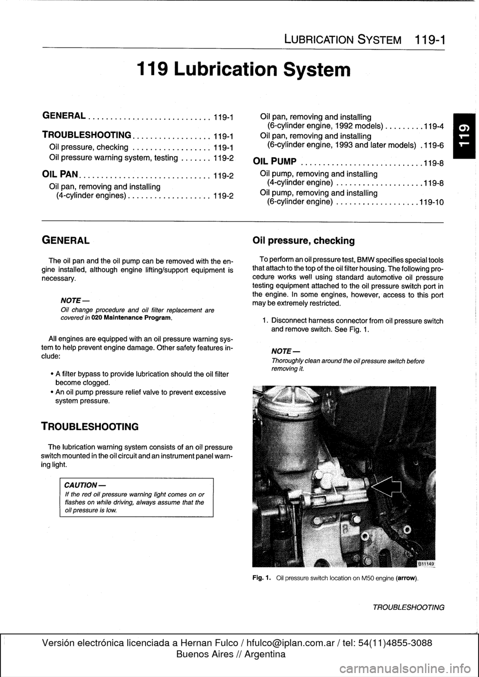
1
.
Disconnect
harness
connector
from
oil
pressure
switch
andremove
switch
.
See
Fig
.
1
.
NOTE-
Thoroughly
clean
around
the
oil
pressure
switchbefore
removing
it
.
Fig
.
1
.
Oil
pressure
switch
location
on
M50
engine
(arrow)
.
TROUBLESHOOTING
Page 116 of 759
119-2
LUBRICATION
SYSTEM
NOTE-
Component
Location
If
the
light
does
not
go
out,
thewiring
to
theswitch
is"
Oil
pressure
switch
most
likely
grounded
somewhere
between
the
switch
all
engines
.......
...
.
..
......
ora
oil
filter
housing
terminal
and
the
warning
light
.
Sea
Electrical
Wiring
Diagrams
atrearof
manual
for
electrical
schematics
.
CAUTION-
Some
oil
may
drain
out
as
the
oil
pressure
switch
is
removed
.
Use
a
rag
to
soak
up
any
spills
.
2
.
Install
pressure
gauge
in
place
of
switch
.
3
.
With
gauge
instalied,
start
engine
and
allow
to
reach
operating
temperature
.
Check
oil
pressureboth
cold
and
hot
.
NOTE-
For
the
most
accurate
test
results,
the
engine
oil
(and
filter)
shouldbe
newand
of
the
correct
grade
.
Oil
Pressure
"
¡dle
(mínimum)
..
.
.
..............
.
.
0
.5
bar
(7psi)
"
Regulated
pressure
(elevated
engine
speed)
4-cylinder
engines
..
......
4
.3
±
0
.2
bar
(63
t3
psi)
6-cylinder
engines
.
.
.............
.
4
.0
bar
(59
psi)
4
.
Remove
pressure
gauge
and
reinstall
pressure
switch
.
If
testing
shows
low
oil
pressure,
one
or
more
of
the
follow-
ing
conditions
may
be
indicated
:
OIL
PAN
"
Worn
or
faulty
oii
pump
.
"
Worn
or
faulty
engine
bearings
The
oil
pancan
be
removed
with
the
engine
instalied,
al-
Severe
engine
wear
.
though
specíal
enginesupport
equipment
will
be
needed
.
Al¡
of
these
conditionsindicate
the
need
for
major
repairs
.
Oil
pressure
warning
system,
testing
When
the
ignition
is
tumed
ora,
the
oil
pressure
warning
light
comes
ora
.
When
the
engine
ís
started
and
the
oil
pressure
ris-
es
slightly,
the
oil
pressure
switch
opens
and
thewarning
light
goes
out
.
Make
sure
the
oil
leve¡
is
correct
before
making
tests
.
1
.
Turra
ignition
switch
ora
.
"
Warning
light
ora
instrument
panel
must
light
up
.
2
.
Remove
connector
from
oil
pressure
switch
.
"
Warning
light
ora
instrument
panel
must
go
out
.
OIL
PAN
3
.
If
warning
light
does
not
light
when
ignition
is
ora,
re-
move
connector
from
oil
pressure
switch
anduse
a
jumper
wire
to
ground
connector
terminal
to
a
clean
metal
surface
.
NOTE
-
If
the
warning
light
comes
ora,
check
the
switch
as
de-
scríbed
in
the
nextstep
.
If
the
warning
light
does
not
come
ora,
thewiring
to
the
instrument
cluster
or
to
the
light
itself
isfaulty
.
4
.
To
test
switch,
connect
ara
ohmmeter
between
terminal
in
switch
body
and
ground
.
With
engine
off,
these
should
be
continuity
.
With
engine
running,
oil
pressure
should
opera
switch
and
there
should
beno
continuity
Replace
a
faulty
switch
.
WARNING
-
Keep
in
mind
that
low
oil
pressure
may
be
prevent-
ing
the
switch
from
tuming
the
light
out
.
If
the
light
remains
ora
while
the
engine
is
running,
check
the
oil
pressure
asdescribed
earlier
.
Do
not
drive
the
car
until
the
problem
is
corrected
.
Theengine
may
be
severely
damaged
.
Oil
pan,
removing
and
installing
(4-cylinder
engines)
1
.
Raise
car
arad
place
securely
ora
jackstands
.
2
.
Remove
splash
shíeld(s)
from
under
engine,
where
ap-
plicable
.
3
.
Drain
engine
oil
as
described
in
020
Maintenance
Pro-
gram
.
4
.
Disconnect
vacuum
hose
adapter
from
vacuum
brake
booster
at
rear
of
engine
compartment
.
5
.
Remove
oil
dipstick
guide
tube
mounting
nut
and
pull
guide
tube
from
oil
pan
.
See
Fig
.
2
.