Testing maf Sensor BMW 325i 1994 E36 Workshop Manual
[x] Cancel search | Manufacturer: BMW, Model Year: 1994, Model line: 325i, Model: BMW 325i 1994 E36Pages: 759
Page 148 of 759

130-2
FUEL
INJECTION
GENERAL
This
repair
group
covers
fuel
injection
system
component
testing
and
repair
.
Special
equipment
is
necessary
for
some
of
the
procedures
given
in
this
repair
group
.
If
you
do
not
have
the
equipment
required
to
do
the
job,
it
is
recommended
that
these
repairs
be
left
to
an
authorized
BMW
dealer
.
The
BMW
dealer
is
equipped
with
sophisticated
diagnostic
test
equip-
ment
that
is
capable
of
quicklypinpointing
hard-to-find
fuel
in-
jection
problems
.
NOTE-
"
Wiring
diagrams
for
the
engine
management
system,
can
be
found
at
the
rear
of
the
manual
under
Electri-
cal
Wiring
Diagrams
.
"
For
ignition
system
repairinformation,
see120
Igni-
tion
System
.
"
For
fuel
supply
system
testing
and
repair,
see160
The
engine
control
module
(ECM)
uses
electrical
signals
Fuel
Tank
and
Fuel
Pump
.
from
the
mass
air
flow
sensor,
the
air
and
coolant
temperature
sensors,
the
crankshaft
position/rpm
sensor,
the
knock
sen
Principies
Of
Operation
sors
and
the
oxygen
sensorsas
the
primary
inputs
to
electron-
ically
control
fuel
delivery
and
ignition
timing
.
There
are
five
versions
of
engine
management
systems
usedon
the
E36
cars
.
Each
has
the
same
basic
components
and
operating
principles
.
The
most
notable
difference
is
that
1996
and
later
cars
use
a
sophisticated
OBD
II-compliant
sys-
tem
.
See
Table
a
.
Table
a
.
Engine
Management
System
Variants
Engine
code/year
1
System
4-cy1inder
M42
(1
.8
I)
1992-1995
Bosch
DME
Ml
.7
M44
(1
.91)
1996-1998
~
Bosch
DME
M5
.2
(OBD
II)
6-cylinder
M50
1992
(2.5
I)
Bosch
DME
M3
.1
1993-1995
(2.5
I)
Bosch
DME
M3
.3.1
(VANOS)
M52
1996-1998
(3281-
2
.8
I)
Siemens
MS
41
.1
(OBD
II)
1998
(3231
-
2
.5
I)
Siemens
MS
41
.1
(OBD
II)
M-Power
S50US
(M3
-
3
.01)
1995
Bosch
DME
M3
.3
.1
S52US
(M3
-
3
.21)
1997-1998
Siemens
MS
41
.1
(0131)
11)
NOTE-
-
Descriptions
and
procedures
in
the
first
partof
this
re-
pairgroup
refer
to
all
the
various
engine
management
systems
.
"
Particulars
of
each
fuel
injection
system
are
treated
in
separate
sections
in
the
second
part
of
this
repair
group
.
GENERAL
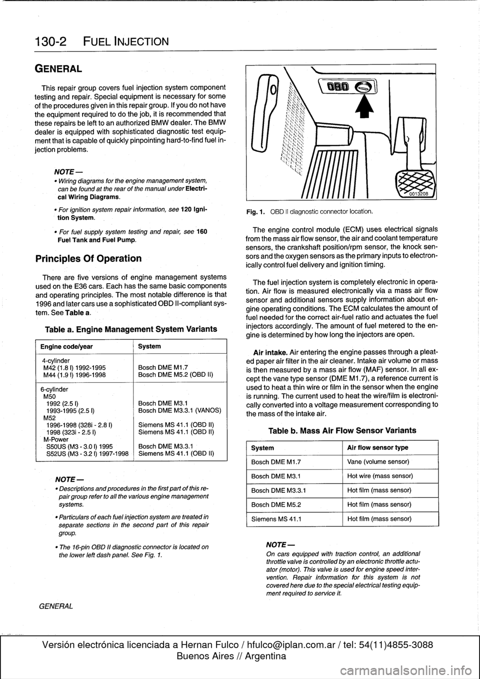
Fig
.1
.
OBD
II
diagnostic
connector
locatíon
.
The
fuel
injection
system
is
completely
electronic
in
opera-
tion
.
Air
flow
is
measured
electronically
via
a
mass
air
flow
sensor
and
additional
sensors
supply
information
about
en-
gine
operating
conditions
.
The
ECM
calculates
the
amount
of
fuel
needed
for
the
correct
air-fuel
ratio
and
actuates
the
fuel
injectors
accordingly
.
The
amount
offuel
metered
to
theen-
gine
is
determined
by
how
long
the
injectors
are
open
.
Airintake
.
Air
entering
the
engine
passes
through
a
pleat-
ed
paper
air
filter
in
the
air
cleaner
.
Intake
air
volume
or
mass
is
then
measured
bya
mass
air
flow
(MAF)
sensor
.
In
al¡
ex-
cept
the
vane
type
sensor
(DME
M1
.7),
a
reference
current
is
used
to
heat
a
thin
wireor
film
in
the
sensor
when
the
engine
is
running
.
The
current
used
to
heat
the
wire/film
is
electroni-
cally
converted
into
a
voltage
measurement
corresponding
to
the
mass
of
the
intake
air
.
Table
b
.
Mass
Air
Flow
Sensor
Variants
System
Al
r
flow
sensor
type
Bosch
DME
M1
.7
Vane
(volume
sensor)
Bosch
DME
M3
.1
Hot
wire
(mass
sensor)
Bosch
DME
M3
.3
.1
Hot
film
(mass
sensor)
Bosch
DME
M5
.2
Hot
film
(mass
sensor)
Siemens
MS
41
.1
Hot
film
(mass
sensor)
"
The
16-pin
OBD
11
diagnostic
connector
is
located
on
NOTE-
the
lower
left
dashpanel
.
See
Fig
.
1
.
On
cars
equipped
wíth
tractioncontrol,
an
additional
throttle
valve
is
controlled
by
an
electronic
throttle
actu-
ator
(motor)
.
This
valve
is
used
for
engine
speed
inter
vention
.
Repair
information
forthis
system
is
notcovered
here
due
to
the
special
electrical
testing
equip-
ment
required
to
service
it
.