air conditioning BMW 325i 1998 E36 User Guide
[x] Cancel search | Manufacturer: BMW, Model Year: 1998, Model line: 325i, Model: BMW 325i 1998 E36Pages: 759
Page 119 of 759
8
.
Remove
air
plenum
from
rear
of
engine
compartment
.
See
640
Heating
and
Air
Conditioning
.
9
.
Release
drive
belt
tension
and
remove
alternator
drive
belt
.
Remove
A/C
compressor
drive
belt
.
See
Fig
.
6
.
B11143
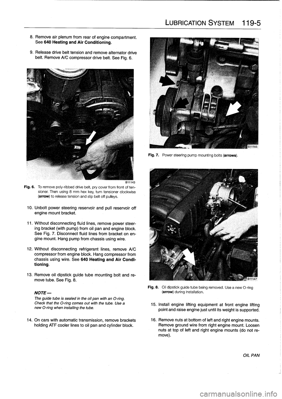
Fig
.
6
.
To
remove
poly-ribbed
drive
belt,
pry
cover
from
front
of
ten-
sioner
.
Then
using
8
mm
hex
key,
turntensioner
clockwise
(arrow)
torelease
tension
and
slip
belt
off
pulleys
.
10
.
Unbolt
power
steering
reservoir
and
pull
reservoir
off
engine
mount
bracket
.
11
.
Without
disconnecting
fluid
lines,
remove
power
steer-
ing
bracket
(with
pump)
from
oil
panand
engine
block
.
See
Fig
.
7
.
Disconnect
fluid
lines
from
bracket
on
en-
gine
mount
.
Hang
pump
from
chassis
using
wire
.
12
.
Without
disconnecting
refrigerant
lines,
remove
A/C
compressor
from
engine
block
.
Hang
compressor
from
chassis
using
wire
.
See
640
Heating
and
Air
Condi-
tioning
.
13
.
Remove
oil
dipstick
guide
tube
mounting
bolt
and
re-
move
tube
.
See
Fig
.
8
.
NOTE-
The
guide
tube
is
sealed
in
the
oil
pan
with
an
O-ring
.
Check
that
the
O-ring
comes
out
with
the
tube
.
Use
anew
O-ring
when
installing
the
tube
.
14
.
On
cars
with
automatic
transmission,
remove
brackets
holding
ATF
cooler
linesto
oil
pan
and
cylinder
block
.
LUBRICATION
SYSTEM
119-
5
Fig
.
7
.
Power
steering
pump
mounting
bolts
(arrows)
.
Fig
.
8
.
Oil
dipstick
guide
tube
being
removed
.
Usea
new
O-ring
(arrow)
during
installation
.
15
.
Insta¡¡
engine
lifting
equipment
at
front
engine
lifting
point
and
raise
engine
just
until
its
weight
is
supported
.
16
.
Remove
nuts
at
bottom
of
left
and
right
engine
mounts
.
Remove
ground
wire
from
right
engine
mount
.
1-oosen
nuts
at
top
of
left
and
right
engine
mounts
(do
not
re-
move)
.
OIL
PAN
Page 145 of 759
Starter,
removing
and
installing
(6-cylinder
engine
with
automatic
transmission)
The
starter
on
a
6-cylinder
car
with
automatic
transmission
ís
removed
from
above
.
It
is
necessary
to
remove
the
íntake
manifold
and
disconnect
a
number
of
electrical
harness
con-
nectors
.
1
.
Disconnect
negative
(-)
battery
cable
.
2
.
Remove
air
plenum
from
rear
of
engine
compartment
.
See640
Heating
and
Air
Conditioning
.
3
.
Remove
top
enginecovers
.
See
Fig
.
9
.
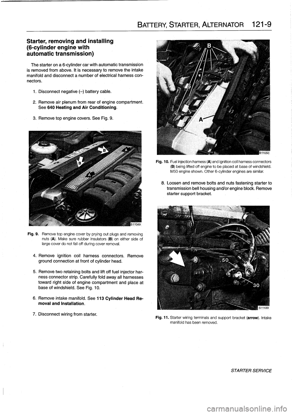
Fig
.
9
.
Remove
top
engine
cover
by
prying
out
plugs
and
removing
nuts
(A)
.
Make
sure
rubber
insulators
(B)
on
either
sideof
large
cover
do
not
fall
off
during
cover
removal
.
4
.
Remove
ignition
coil
harness
connectors
.
Remove
ground
connection
at
front
of
cylinder
head
.
5
.
Remove
two
retaining
bolts
and
lift
off
fuel
injector
har-
ness
connector
strip
.
Carefully
fold
away
all
harnesses
toward
right
side
of
engine
compartment
and
place
at
base
of
windshield
.
See
Fig
.
10
.
6
.
Remove
intake
manifold
.
See
113
Cylinder
Head
Re-
moval
and
Installation
.
7
.
Disconnect
wiring
from
starter
.
BATTERY,
STARTER,
ALTERNATOR
121-
9
Fig
.
10
.
Fuel
injection
harness
(A)
and
ignition
coíl
harness
connectors
(B)
being
lifted
off
engine
to
be
placed
at
base
ofwindshield
.
M50
engine
shown
.
Other
6-cylinder
engines
are
similar
.
8
.
Loosen
and
remove
bolts
and
nuts
fastening
starter
to
transmission
bell
housing
and/or
engine
block
.
Remove
starter
support
bracket
.
Fig
.
11
.
Starter
wiring
terminals
and
support
bracket(arrow)
.
Intake
manifold
has
been
removed
.
STARTER
SERVICE
Page 195 of 759
170
Radiator
and
Cooling
System
GENERAL
.
.
.....
.
...
.
.
.
.
.
....
.
.
.
.
.
.
.
.170-1
Coolant
Pump
and
Thermostat
........
.
.
.
.
170-1
Radiator
and
Expansion
Tank
.........
.
...
170-1
Cooling
Fans
.
....
.
.
.
.
.
.
.
.
.
.....
.
......
170-2
Warnings
and
Cautions
.
.
.
.
.
.
.
.
.
.
.
.
...
.
.
.
170-2
TROUBLESHOOTING
...
.
.
.
...
.
.
.
.
.
.
.
.
.170-2
Cooling
System
Pressure
Test
...
.
.
.
.
.
.
.
.
.
170-3
Thermostat
Quick
Check
.
.
.
.
...
.
.
.
.
.
.
.
.
.
170-3
Temperature
Gauge
Quick
Check
.
.
.
.
.
.
.
.
.
170-3
Cooling
fan,
testing
.
.
.
.
........
.
.
.
.
.
.
.
.
.
170-4
COOLING
SYSTEM
SERVICE
.
.
.
.
.
.
.
.
.
.
170-5
Coolant,draining
and
filling
.
.
......
.
.
.
.
.
..
170-5
Cooling
system,
bleeding
(radiator
with
integral
expansion
tank)
.....
170-6
GENERAL
This
section
covers
repair
and
troubleshooting
information
for
the
engine
cooling
system
.
For
heater
core
and
related
heating
and
air
conditioning
components,
see640
Heating
and
Air
Conditioning
.
Coolant
Pump
and
Thermostat
A
centrifuga¡-type
coolant
pump
is
mounted
to
the
front
of
the
engíne
.
The
belt-driven
pump
circulates
coolant
through
the
system
whenever
the
engíne
is
running
.
A
thermostat
con-
trols
the
flow
of
coolant
into
the
radiator
.
When
the
engíne
is
cold
the
thermostat
is
closed
so
coolant
bypasses
the
radiator,
recirculating
from
the
engíne
directly
back
to
the
pump
.
When
the
engíne
reaches
operating
tem-
perature,
the
thermostat
opens
and
coolant
circulates
through
the
whole
system
including
the
radiator
.
Radiator
and
Expansion
Tank
The
radiator
is
a
crossflow
design
.
A
translucent
expansion
tank
provides
for
coolant
expansion
at
higher
temperatures
and
easy
monitoringof
the
coolant
leve¡
.
On
4-cylinder
modeis,
the
radiator
expansion
tank
is
integral
with
the
radiator
.
See
Fig
.
1
.
RADIATOR
AND
COOLING
SYSTEM
170-1
Belt-driven
cooling
fan,
replacing
.
.......
.
.
.
170-7
Electric
cooling
fan,
replacing
.
.
.
.....
.
.
.
.
.
170-8
Auxiliary
cooling
fan,
replacing
.
.
.....
.
.
.
.
.
170-8
Thermostat,
replacing
.
.
.
.
.
.
.
.
.
.....
.
.
.
.
.
170-9
Coolant
pump,
replacing
..........
.
.
.
.
.
.
170-10
RADIATOR
SERVICE
.....
.
......
.
.
.
.
.
.
170-11
Radiator,
removing
and
installing
....
.
.
.
.
.
.
170-11
TABLES
a
.
Coolant
Temperature
Sensor
Wire
Colors
...
.
..
.
.
170-3b
.
Auxiliary
Cooling
Fan
Switching
Temperatures
.:.
.170-4
c
.
Auxiliary
Cooling
Fan
Temperature
Switch
Tests
..
..
.
...
...
.
.............
.
..
.
.
170-5d
.
Cooling
System
Capacities
..............
..
.
.
.
170-6
A
.
Expansion
tank
C
.
Dualtemperature
fan
switch
B
.
Radiator
drain
screw
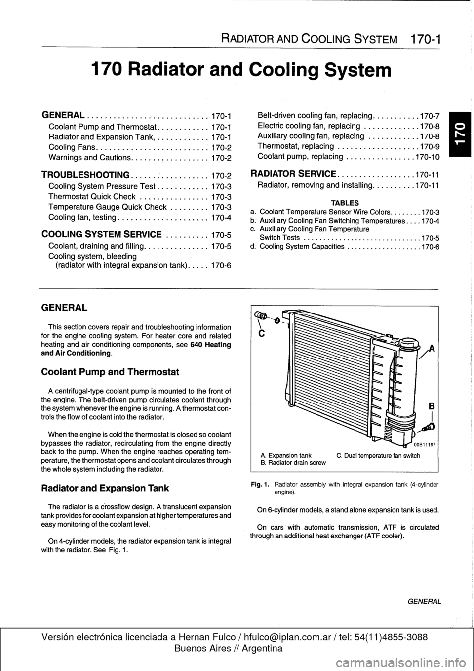
Fig
.
1
.
Radiator
assembly
with
integral
expansion
tank
(4-cylinder
engine)
.
On
6-cylinder
models,
a
standalone
expansion
tank
is
used
.
On
cars
with
automatic
transmission,
ATF
is
circulated
through
an
additional
heat
exchanger
(ATF
cooler)
.
GENERAL
Page 198 of 759
170-
4
RADIATOR
AND
COOLING
SYSTEM
A
quick
testat
the
coolant
temperature
gauge
sender
can
The
auxiliary
cooling
fan
comes
on
when
coolant
tempera
determine
if
the
gauge
is
functioning
correctly
.
ture
exceeds
a
predetermined
leve¡
or
whenever
the
air
condi-
tioning
is
on
.
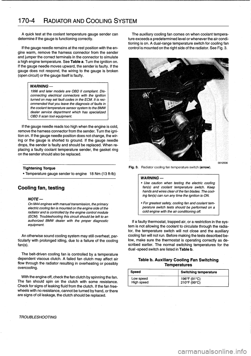
A
dual-range
temperature
switch
for
cooling
fan
lf
the
gauge
needie
remains
at
the
rest
position
with
theen-
control
is
mounted
on
the
right
side
of
the
radiator
.
See
Fig
.
3
.
gine
warm,
remove
the
harness
connector
from
the
sender
and
jumper
the
correct
terminals
in
the
connector
to
simulate
a
high
engine
temperature
.
See
Table
a
.
Turn
the
ignition
on
.
If
the
gauge
needle
moves
upward,
the
sender
is
faulty
.
If
the
gauge
does
not
respond,
the
wiring
to
the
gauge
is
broken
(open
circuit)
or
the
gauge
itselfis
faulty
.
WARNING
-
1996
and
laten
models
are
OBD
11
compliant
.
Dis-
connecting
electrical
connectors
wíth
the
ignition
turned
on
may
set
fault
codes
in
the
ECM
.
It
is
rec-
ommended
that
you
leave
the
diagnosis
of
faults
in
the
coolant
temperature
sensorsystem
to
the
BMW
dealer
service
department
which
has
specialized
OBD
11
scan
tool
equipment
.
If
the
gauge
needle
reads
too
high
when
the
engine
is
cold,
remove
the
harness
connector
from
the
sender
.
Turn
the
igni-
tion
on
.
lf
the
gauge
needle
position
does
not
change,
the
wir-
ing
or
the
gauge
is
shorted
to
ground
.
If
the
gauge
needle
drops,
the
sender
is
faulty
and
should
be
replaced
.
When
re-
placing
a
faulty
coolant
temperature
sender,
the
gasket
ring
on
the
sender
should
also
be
replaced
.
Tightening
Torque
"
Temperature
gauge
sender
to
engine
18
Nm
(13
ft-Ib)
Cooling
fan,
testing
NOTE-
OnM44
engines
with
manual
transmission,
the
primary
electric
cooling
fan
is
mounted
on
the
engine
side
of
the
radiator
and
is
controlled
by
the
engine
control
module
(ECM)
.
Troubleshooting
thiscircuit
should
be
left
to
an
authorized
BMW
dealer
with
the
proper
diagnostic
equipment
An
otherwise
sound
cooling
system
may
still
overheat,
par-
ticularly
with
prolonged
idling,
due
to
a
failure
of
the
coolíng
fan(s)
.
The
belt-driven
cooling
fan
is
controlled
by
a
temperature
dependent
viscous
clutch
.
A
failed
fan
clutch
may
affect
air
flow
through
the
radiator
resulting
in
overheating
orpossibly
overcooling
.
Speed
Low
sp
High
s
With
the
engine
off,
check
thefan
clutch
by
spinning
thefan
.
eed
The
fan
should
spin
on
the
clutch
with
some
resistance
.
peed
Check
for
signs
of
leaking
fluid
from
the
clutch
.
If
thefan
free-
wheels
with
no
resistance,
cannot
be
tu
rned
by
hand,
or
there
are
signs
of
oil
leakage,
the
clutch
should
be
replaced
.
TROUBLESHOOTING
Fig
.
3
.
Radiatorcooling
fan
temperature
switch
(arrow)
.
WARNING
-
"
Use
caution
when
testing
the
electric
cooling
fan(s)
and
coolant
temperature
switch
.
Keep
hands
and
wires
clear
of
thefan
blades
.
The
cool-
ing
fan(s)
can
run
any
time
the
ignition
is
ON
.
"
For
greatest
safety,
coolíng
fan
and
coolant
tem-perature
switch
tests
shouldbe
performed
on
acoldengine
with
the
air
conditioning
off
.
Table
b
.
Auxiliary
Cooling
Fan
Switching
Temperatures
Switching
temperature
196°F(91°C)
210°F(99°C)
0012506
If
a
faulty
thermostat,
trapped
air,
or
a
restriction
in
the
sys-
tem
is
not
allowing
the
coolant
to
circulate
through
the
radia-
tor,
the
temperature
switch
will
not
close
and
the
auxiliary
cooling
fan
will
not
run
.
Before
making
the
tests
described
be-
low,
make
sure
the
thermostat
is
operating
correctly
as
de-
scribed
earlier
.
The
normal
switching
temperatures
for
the
dual
-speed
switch
are
listed
in
Table
b
.
Page 204 of 759
170-10
RADIATOR
AND
COOLING
SYSTEM
Coolant
pump,
replacing
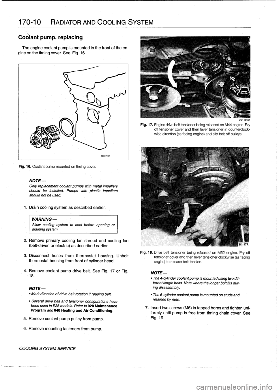
The
engine
coolant
pump
is
mounted
in
the
frontof
the
en-
gine
on
the
timing
cover
.
See
Fig
.
16
.
Fig
.
16
.
Coolant
pump
mounted
on
timing
cover
.
NOTE-
Onlyreplacement
coolant
pumps
with
metal
¡mpellers
should
be
installed
.
Pumps
with
plastic
impellers
should
not
be
used
.
1.
Drain
cooling
system
as
described
earlier
.
0013197
WARNING
-
Allow
cool¡ng
system
to
cool
before
open¡ngor
drain¡ng
system
.
2
.
Remove
primary
cooling
fan
shroud
and
cooling
fan
(belt-driven
or
electric)
as
described
earlier
.
Fig
.
17
.
Engine
drive
belt
tensioner
being
released
on
M44
engine
.
Pry
off
tensioner
cover
and
then
lever
tensioner
in
counterciock-
wise
direction
(as
facing
engine)
and
slip
belt
off
pulleys
.
Fig
.
18
.
Drive
belt
tensioner
being
released
on
M52
engine
.
Pry
off
3
.
Disconnect
hoses
from
thermostat
housing
.
Unbolt
tensioner
cover
and
then
lever
tensioner
clockwise
(as
facing
thermostat
housing
from
front
of
cylinder
head
.
engine)torelease
belt
tension
.
4
.
Remove
coolant
pump
drive
belt
.
See
Fig
.
17
or
Fig
.
18
.
NOTE-
-
Mark
direction
of
drive
belt
rotation
if
reusing
belt
.
"
The
6-cylinder
coolant
pump
¡s
mounted
on
studs
and
retained
by
nuts
.
"
Severa¡
drive
belt
and
tensioner
configurations
havebeenused
in
E36
models
.
Refer
to
020
Maintenance
Program
and
640
Heating
and
Air
Conditioning
.
5
.
Remove
coolant
pump
pulley
from
pump
.
6
.
Remove
mounting
fasteners
from
pump
.
COOLING
SYSTEM
SERVICE
NOTE-
"
The
4-cylinder
coolant
pump
¡s
mounted
us¡ng
two
dif-
terent
length
bolts
.
Note
where
thelonger
bolt
fits
dur-
ing
disassembly
.
0011989
7
.
Insert
twoscrews
(M6)
in
tapped
bores
and
tighten
uni-
formly
until
pump
is
free
from
timing
chain
cover
.
See
Fig
.
19
.
Page 291 of 759
Brake
rotor,
removing
and
installing
.
.
.
.
.
.
.
.
340-7
MASTER
CYLINDER
............
.
.
.
.
.
.
.340-7
Master
cylinder,
removing
and
installing
.
...
.
340-7
GENERAL
TROUBLESHOOTING
WARNING
-
"
Although
semi-metallic
and
metallic
Brake
friction
materials
in
Brake
pads
or
shoes
no
longer
con-
tain
asbestos,
they
produce
dangerous
dust
.
"
Brake
fluid
is
poisonous,
highly
corrosive
and
dangerous
to
the
environment
Wear
safety
glasses
and
rubber
gloves
when
working
with
Brake
fluid
.
Do
not
siphonBrake
fluid
with
your
mouth
.
Immediately
clean
away
any
fluid
spilled
on
painted
surfaces
and
wash
with
water,
asBrake
fluid
will
remove
paint
.
"
Always
use
new
Brake
fluid
froma
fresh,
un-
opened
container
.
Brake
fluid
will
absorb
mois-
ture
from
the
air
.
This
canlead
to
corrosion
problems
in
the
brakingsystem,
and
will
also
low-
er
the
Brake
fluid's
boiling
point
.
Dispose
of
Brake
fluid
properly
.
"
Do
notreuse
self-locking
nuts,bolts
or
fasteners
.
They
are
designed
to
be
used
only
once
and
may
failif
reused
.
Always
replace
them
with
new
self-
locking
fasteners
.
BMW
E36
models
areequipped
with
vacuum
power-assist-
ed
four-wheel
disc
brakes
with
an
integral
Antilock
Brake
Sys-
tem
(ABS)
.
Single-pistoncalipers
act
on
solid
or
vented
front
rotors
and
solid
rear
rotors
.
A
brake
pad
wear
sensor
for
each
axle
indicates
when
brake
padsneed
replacement
.
The
dual
drum-type
parking
brakesystem
is
integrated
with
the
rear
brake
rotors
.
NOTE-
M3
models
havevented
directional
Brake
rotors
on
the
rearaxle
as
well
ason
the
front
.
340
Brakes
BRAKES
340-1
GENERAL
.
.
.
.
.
.
.........
.
.
.
..........
340-1
BRAKE
BOOSTER
.........
.
.
.
.
.
...
.
.
.
.
340-8
TROUBLESHOOTING
.......
.
......
.
...
340-1
Brake
booster,
removing
and
installing
....
.
.
340-8
PARKING
BRAKE
.
.....
.
...
.
.
.
.....
.
.
.
340-10
BLEEDING
BRAKES
.
.
.
.
.
.
.
.
..........
340-3
Parking
brake,adjusting
.
.
.
.
.
.
.
.
.
.
.....
.
340-10
Pressure
bleeding
brakes
Parking
brake
shoes,
removing
and
installing
.
340-11(except
cars
with
AST)
.
.
.
.
.
.
.
.
.
...
.
.
.
.
.340-3
Parking
Brake
cable,
replacing
.
.
.
.
.
.
.
.
.
.
.
.
340-11
BRAKE
PADS,
CALIPERS,
ANTILOCK
BRAKE
SYSTEM
(ABS)
.
.
.
.340-11
AND
ROTORS
..........
.
.......
.
.
.
.
.
.
.
340-3
ABS
System
Inspection
.
...
.
.......
.
.
.
..
340-12
Brake
pads,
replacing
............
.
.
.
.
.
.
.
340-4
ABS
wheel
speed
sensors,
replacing
.
.
.
.
..
340-12
Brake
caliper,
removing
and
installing
.
..
..
.
340-6
TABLES
a
.
Brake
System
Troubleshooting
.....
...
.
.
.....
.340-2
b
.
Brake
Rotor
Reconditioning
Specifications
.
.....
.340-7
Brakeperformance
is
mainly
affected
by
three
things
:
the
leve¡
and
condition
of
the
brake
fluid,
the
system's
abilíty
to
create
and
maintain
hydraulic
pressure,
and
the
condition
of
the
friction
components
.
Air
in
the
Brake
fluid
will
make
the
Brake
pedal
feel
spongy
during
braking
or
will
increase
the
Brake
pedalforce
required
to
stop
.
Fluid
contaminated
by
moisture
or
dirt
can
corrode
the
system
.
Inspect
the
Brake
fluid
inside
the
reservoir
.
Ifit
is
dirty
or
murky,
or
is
over
a
year
old,
the
fluid
should
be
replaced
.
Visually
check
the
hydraulic
system
startingat
the
master
cylinder
.
To
check
the
function
of
the
master
cylinder
hold
the
brake
pedal
down
hard
with
the
engine
running
.
The
pedal
should
feelsolid
and
stay
solid
.
If
the
pedal
slowly
falls
to
the
floor,
either
the
master
cylinder
is
leaking
internally,
or
fluid
is
leaking
externally
.
If
no
leaks
canbe
found,
the
master
cylin-
der
is
faulty
and
should
be
replaced
.
Check
all
Brake
fluid
lines
and
couplings
for
leaks,
kinks,
chafing
and
corrosion
.
Check
the
Brake
booster
by
pumping
the
Brake
pedal
ap-
proximately
10
times
with
the
engine
off
.
Hold
the
pedal
down
and
start
the
engine
.
The
pedal
should
fa¡¡
slightly
.
If
not,
check
for
any
visiblefaults
before
suspecting
a
faulty
brake
booster
.
Check
for
strong
vacuum
at
the
vacuum
hose
fitting
at
the
booster,
and
check
the
non-retum
valve
for
one-way
flow
.
Worn
or
contaminated
brake
pads
will
cause
poor
braking
performance
.
Oil-contaminated
or
glazed
pads
will
cause
stopping
distances
to
increase
.
Inspect
the
rotors
for
glazing,
discoloration
and
scoring
.
Steering
wheel
vibration
while
braking
at
speed
is
often
caused
by
warped
rotors,
but
can
also
be
caused
byworn
suspension
components
.
TROUBLESHOOTING
Page 297 of 759
Brake
rotor,
removing
and
installing
Brake
rotors
shouldalways
be
replaced
in
pairs
.
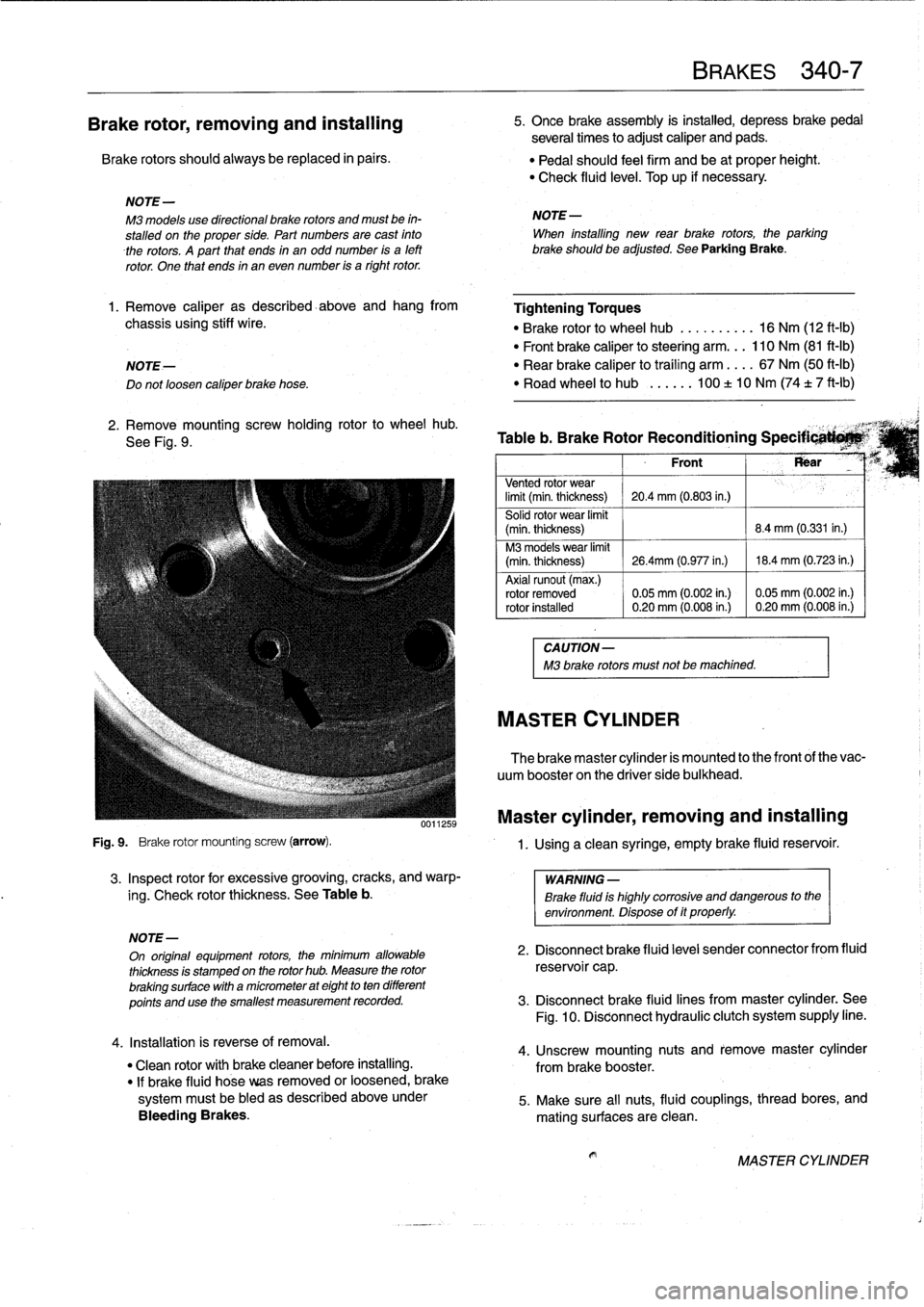
Fig
.
9
.
Brake
rotor
mounting
screw
(arrow)
.
3
.
Inspect
rotor
for
excessive
grooving,
cracks,
and
warp-
ing
.
Check
rotor
thickness
.
See
Table
b
.
4
.
Installation
is
reverse
of
removal
.
"
Clean
rotor
with
brakecleaner
before
installing
.
"
If
brake
fluid
hose
veas
removed
or
loosened,
brake
systemmustbe
bled
as
described
aboveunder
Bleeding
Brakes
.
BRAKES
340-
7
5
.
Once
brake
assembly
is
instalind,
depress
brakepedal
several
times
to
adjust
caliper
and
pads
.
"
Pedal
should
feel
firm
and
be
at
proper
height
.
"
Check
fluid
leve¡
.
Top
up
if
necessary
.
NOTE-
M3
models
use
directional
brake
rotors
and
mustbe
in-
NOTE-
stalled
on
the
proper
side
.
Part
numbes
are
cast
finto
When
installing
new
rear
brake
rotors,
the
parking
therotors
.
A
part
that
ends
in
an
odd
number
is
a
left
brakeshouldbe
adjusted
.
See
Parking
Brake
.
rotor
.
One
that
ends
in
an
even
number
is
a
right
rotor
.
1.
Remove
caliper
as
described-above
and
hang
from
Tightening
Torques
chassis
using
stiff
wire
.
"
Brake
rotor
to
wheel
hub
..........
16
Nm
(12
ft-Ib)
"
Front
brake
caliper
to
steering
arm
...
110
Nm
(81
ft-Ib)
NOTE-
"
Rear
brake
caliper
to
traíling
arm
....
67
Nm
(50
ft-Ib)
Do
notloosen
caliper
brake
hose
.
"
Road
wheel
to
hub
...
..
.
100
±
10
Nm
(74
t
7
ft-Ib)
2
.
Remove
mountingscrew
holding
rotor
to
wheel
hub
.
,
See
Fig
.
9
.
Table
b
.
Brake
Rotor
Reconditioning
Specificati*M`
Front
Rear
Vented
rotor
wear
limit
(min
.
thickness)
20
.4
mm
(0
.803
in.)
Solid
rotor
wear
limit
(min
.
thickness)
8
.4
mm
(0.331
in
.)
M3
models
wear
limit
(min
.
thickness)
26
.4mm
(0
.977
in
.)
18
.4
mm
(0
.723
in
.)
Axial
runout
(max
.)
rotor
removed
0
.05
mm
(0
.002
in
.)
0
.05
mm
(0
.002
in
.)
rotor
installed
0
.20
mm
(0
.008
in
.)
0
.20
mm
(0
.008
in
.)
CAUTION-
M3
brake
rotors
must
not
be
machined
.
MASTER
CYLINDER
The
brake
master
cylinder
is
mounted
to
the
front
of
the
vac-
uum
booster
on
the
driver
side
bulkhead
.
Master
cylinder,
removing
and
installing
1
.
Using
a
clean
syringe,
empty
brake
fluid
reservoir
.
WARNING
-
Brake
fluid
is
highly
corrosive
and
dangerous
to
the
environment
.
Dispose
of
it
properly
.
NOTE-
On
original
equipment
rotors,
the
mínimum
allowable
2
.
Disconnect
brake
fluid
leve¡
sender
connector
from
fluid
thickness
is
stamped
on
the
rotor
hub
.
Measure
the
rotor
reservoi
r
cap
.
brakingsurface
with
a
micrometer
at
eight
to
ten
different
points
and
use
the
smallest
measurement
recorded
.
3
.
Disconnect
brake
fluid
lines
frommaster
cylinder
.
See
Fig
.
10
.
Disconnect
hydraulic
clutch
system
supply
line
.
4
.
Unscrew
mounting
nuts
and
remove
master
cylinder
from
brake
booster
.
5
.
Make
sure
all
nuts,
fluid
couplings,
thread
bores,
and
mating
surfaces
are
clean
.
MASTER
CYLINDER
Page 303 of 759
GENERAL
.
....
.
.
.
.
.
.......
.
.
.
.
.
...
.
.
.
400-1
INTERIOR
EQUIPMENT
......
.
.
.
.......
400-4
Seats
and
Seatbelts
.
.
.
.
.
.
.....
.
.
.
.
.
..
.
..
400-4
BODY
ASSEMBLY
.
.
.
.
.
.....
.
.
.
.
.
.
.
.
.
.
.400-2
Instruments
and
Controls
.
..
....
.
.
.
.
.
.
.
...
400-4
Exterior
and
Aerodynamics
....
.
.
.
.
.
.
.
.
.
.
.
400-2
Central
Body
Electronics
.......
.
.
.
...
.
...
400-5
Coupe
Models
..
.
.
.
.
.
.......
.
.
.
.
.
.
.
.
.
..
400-3
Electronic
Immobilization
System
.
.
.
...
.
...
400-5
Convertible
Models
.
.
.
.
.
.
.
.....
.
.
.
.
.
.
.
..
400-3
Heating
and
Air
Conditioning
.
...
.
.
.
.
.
.
.
...
400-6
GENERAL
This
section
covers
system
descriptions
and
general
ser-
vice
information
for
the
repair
groupsfound
in
4
Body
and
5
Body
Equipment
.
When
working
or
servicing
cars
equipped
with
SRS
air-
bag(s),
the
following
precautions
must
be
observed
to
prevent
injury
.
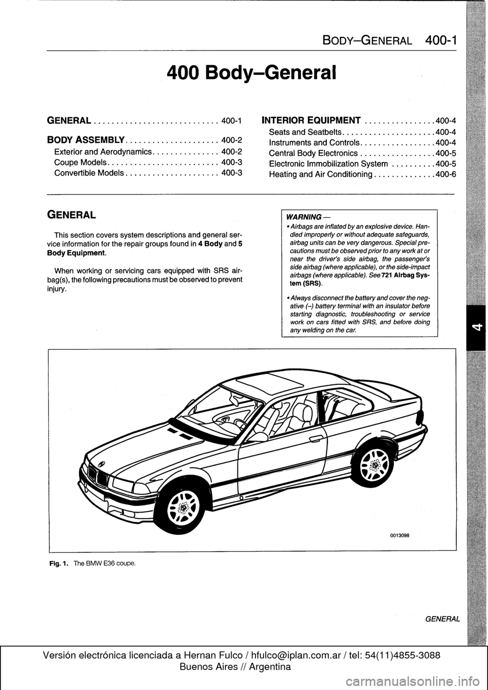
F19
.1
.
The
BMW
E36
coupe
.
400
Body-General
BODY-GENERAL
400-1
WARNING
-
"
Airbags
are
inflated
by
an
explosivedevice
.
Han-dled
improperly
or
without
adequate
safeguards,
airbag
units
can
be
very
dangerous
.
Special
pre-cautions
must
be
observed
prior
to
any
work
ator
near
the
driver's
side
airbag,
the
passenger's
side
airbag
(where
applicable),
or
the
side-impact
aírbags
(where
applicable)
.
See
721
Airbag
Sys-
tem
(SRS)
.
"
Always
disconnect
the
battery
and
cover
the
neg-
ative
(-)
battery
terminalwith
an
insulator
before
starting
diagnostic,
troubleshooting
or
service
work
oncars
fitted
with
SRS,
and
before
doíng
any
welding
on
the
car
.
0013098
GENERAL
Page 308 of 759
400-
6
BODY-GENERAL
Heating
and
Air
Conditioning
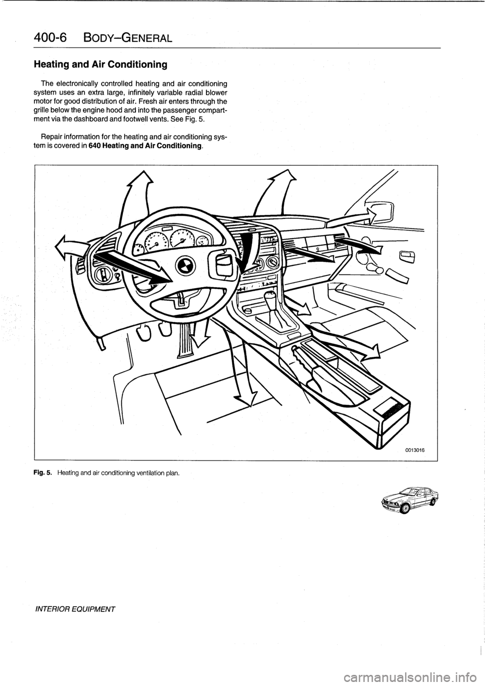
The
electronically
controlled
heating
and
air
conditioning
systemusesan
extra
large,
infinitely
variable
radial
blower
motor
for
good
distribution
of
air
.
Fresh
air
enters
through
the
grille
below
the
engine
hood
and
finto
the
passenger
compart-
ment
via
the
dashboard
and
footwell
vents
.
See
Fig
.
5
.
Repair
information
for
the
heating
and
air
conditioning
sys-
tem
is
covered
in
640
Heating
and
Air
Conditioning
.
Fig
.
5
.
Heating
and
air
conditioning
ventilation
plan
.
INTERIOR
EQUIPMENT
Page 347 of 759
Dashboard,
removing
and
installing
1
.
Disconnect
negative
(-)
cable
from
battery
and
cover
terminal
with
insulating
material
.
CAUTION-
Prior
to
disconnectiog
the
battery,
read
the
battery
disconnection
cautionsgiven
at
the
front
of
this
manual
onpage
vi¡¡
.
2
.
Remove
center
console
as
described
earlier
.
3
.
Remove
glove
compartment
as
described
earlier
.
4
.
Remove
lower
left
dash
trim
piece
as
described
above
.
Remove
lower
right
dash
trim
panel
.
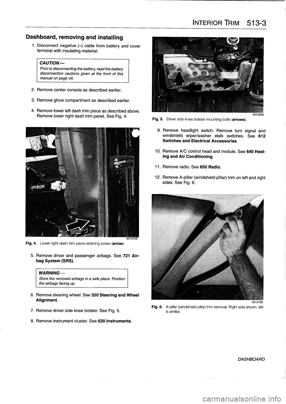
See
Fig
.
4
.
Fig
.
4
.
Lower
right
dash
trim
piece
retaining
screw
(arrow)
.
WARNING
-
Store
the
removed
airbags
in
a
safe
place
.
Position
the
airbags
facing
up
.
8
.
Remove
instrument
cluster
.
See
620
Instruments
.
5
.
Remove
driver
and
passenger
airbags
.
See
721
Air-
bag
System
(SRS)
.
6
.
Remove
steering
wheel
.
See
320
Steering
and
Wheel
Alignment
.
INTERIOR
TRIM
513-
3
Fig
.
5
.
Driver
side
knee
bolster
mounting
bolts
(arrows)
.
9
.
Remove
headlight
switch
.
Remove
turn
signal
and
windshield
wiper/washer
stalk
switches
.
See612
Switches
and
Electrical
Accessories
.
10
.
Remove
A/C
control
head
and
module
.
See
640
Heat-ing
and
Air
Conditioning
.
11
.
Remove
radio
.
See650
Radio
.
12
.
Remove
A-pillar
(windshield
pillar)
trim
on
left
and
right
sides
.
See
Fig
.
6
.
UU13156
Fig
.
6
.
A-pillar
(windshield
pillar)
trim
removal
.
Right
side
shown,
left
7
.
Remove
driver
side
knee
bolster
.
See
Fig
.
5
.
is
similar
.
DASHBOARD