engine oil BMW 328i 1995 E36 Workshop Manual
[x] Cancel search | Manufacturer: BMW, Model Year: 1995, Model line: 328i, Model: BMW 328i 1995 E36Pages: 759
Page 224 of 759
230-
4
MANUAL
TRANSMISSION
Output
shaft
sea¡,
replacing
(transmission
installed)
1
.
Raise
and
safely
support
vehicle
.
Support
transmission
with
transmission
jack
.
WARNING
-
"
When
raising
thecar
using
a
floor
jack
or
a
hy-
draulic
lift,
carefully
position
the
jack
pad
to
pre-vent
damaging
the
car
body
.
A
suitable
liner
(wood,
rubber,
etc
.)
should
be
placed
between
the
jack
and
the
car
to
prevent
body
damage
.
"
Watch
the
jack
closely
.
Make
sure
it
stays
stable
and
does
not
shift
or
tilt
.
As
the
car
is
raised,
the
car
may
roll
slightly
and
the
jack
may
shift
.
2
.
Remove
driveshaft
.
See
260
Driveshaft
.
3
.
Remove
transmission
crossmember
and
lower
trans-
mission
at
rear
.
CAUTION-
Tilting
the
engine
to
lower
thetransmissíon
can
lead
to
damage
to
various
componente
due
to
lackof
clearance
.
-On
cars
with
AST
(traction
control)
remove
throt-
tle
body
before
tilting
engine
.
-Remove
brake
fluid
reservoir
if
necessary
.
4
.
Bend
back
and
remove
collar
nut
lockplate
.
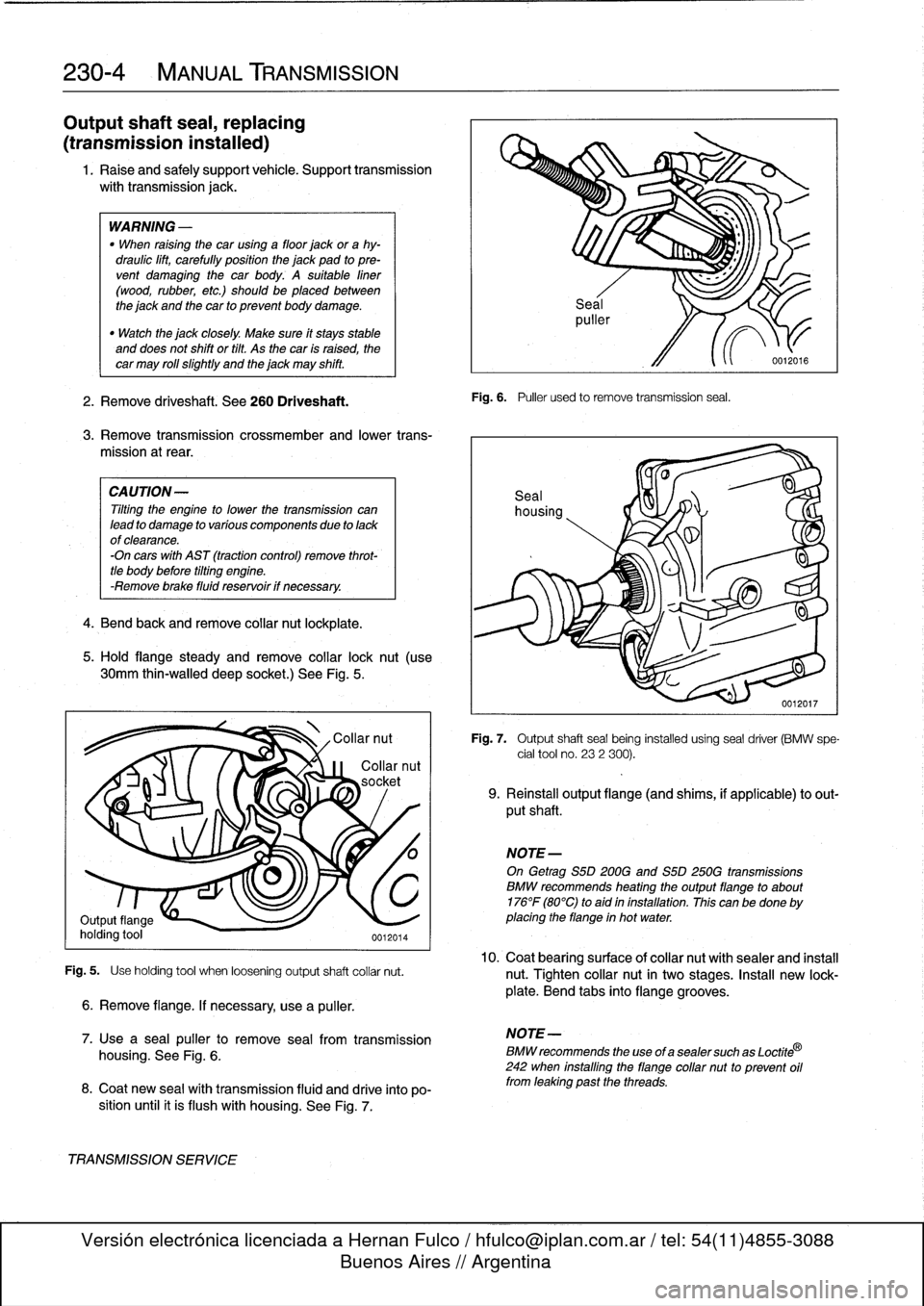
5
.
Hold
flange
steady
andremove
collar
lock
nut
(use
30mm
thin-walled
deep
socket
.)
See
Fig
.
5
.
Fig
.
5
.
Use
holding
tool
when
loosening
output
shaft
collar
nut
.
6
.
Remove
flange
.
If
necessary,
use
a
puller
.
7
.
Use
a
sea¡
puller
to
remove
seal
from
transmission
housing
.
See
Fig
.
6
.
8
.
Coat
new
sea¡
wíth
transmission
fluid
and
drive
into
po-
sition
until
it
is
flush
with
housing
.
See
Fig
.
7
.
TRANSMISSIONSERVICE
Fig
.
6
.
Puller
used
to
remove
transmission
seal
.
Fig
.
7
.
Output
shaftseal
being
installed
using
seal
driver
(BMW
spe-
cial
tool
no
.
232
300)
.
9
.
Reinstall
output
flange
(and
shims,
if
applicable)
to
out-
put
shaft
.
NOTE-
On
Getrag
S5D200G
and
S5D
250G
transmissions
BMW
recommends
heating
theoutputflange
to
about
176°F
(80°C)
to
aid
in
installation
.
This
canbe
done
by
placing
the
flange
in
hot
water
.
10
.
Coat
bearingsurface
ofcollar
nut
withsealer
and
install
nut
.
Tighten
collar
nut
in
two
stages
.
Insta¡¡
new
lock-
plate
.
Bend
tabs
into
flange
grooves
.
NOTE-
BMW
recommends
the
use
of
a
sealer
such
as
Loctite
®
242
when
installing
the
flange
collar
nut
to
prevent
oil
from
leaking
past
the
threads
.
Page 225 of 759
11
.
Raise
transmission
and
reinstall
transmission
cross-
member
.
12
.
Install
driveshaft
using
new
nuts
.
See
260
Driveshaft
.
13
.
Check
transmission
oil
leve¡,
topping
up
asnecessary
.
Tightening
Torques
"
Transmission
crossmember
to
chassis
M8
...............
.
...
.
..
22-24
Nm
(16-17
ft-Ib)
M10
..............
.
..
...
..
.
...
42
Nm
(31
ft-Ib)
"
Transmission
outputflange
to
output
shaft
O
001202
2
Z
:Z
ZZZ~
%
_
j
Stage
I.................
..
.
..
190
Nm
(140
ft-Ib)
Stage
II
(after
loosening)
....
.
.
.
..
120
Nm
(89
ft-Ib)
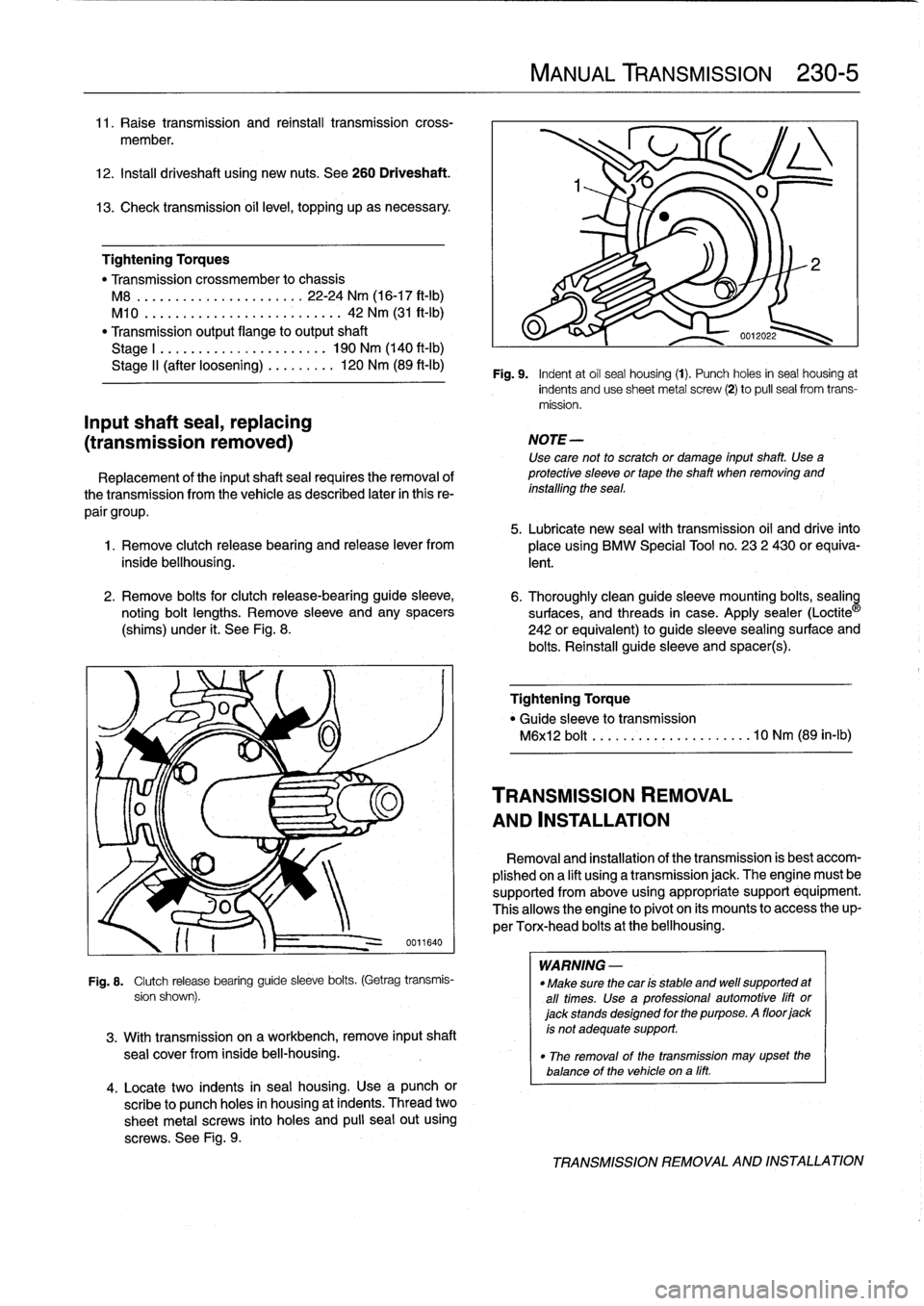
Fi
g
.
9
.
Indent
at
oil
seal
housing
(1)
.
Punch
holes
in
seal
housing
at
Inputshaft
sea¡,
replacing
(transmission
removed)
Replacement
of
the
inputshaft
sea¡
requires
the
removal
of
thetransmission
from
the
vehicle
as
described
later
in
this
re-
pair
group
.
5
.
Lubricate
new
sea¡with
transmission
oil
and
drive
into
1
.
Remove
clutch
release
bearing
and
release
lever
from
placeusing
BMW
Special
Tool
no
.
23
2
430
or
equiva-
inside
bellhousing
.
lent
.
2
.
Remove
bolts
for
clutch
release-bearing
guide
sleeve,
6
.
Thoroughly
cleanguide
sleeve
mounting
bolts,
sealin
noting
bolt
lengths
.
Remove
sleeve
and
any
spacers
surfaces,
and
threads
in
case
.
Apply
sealer
(Loctite
(shims)
under
¡t
.
See
Fig
.
8
.
242
or
equivalent)
to
guide
sleeve
sealingsurface
and
bolts
.
Reinstall
guide
sleeve
and
spacer(s)
.
0011640
Fig
.
8
.
Clutch
release
bearing
guide
sleeve
bolts
.
(Getrag
transmis-
sion
shown)
.
3
.
With
transmission
on
aworkbench,
remove
input
shaft
sea¡
cover
from
inside
bel¡-housing
.
4
.
Locate
two
indents
in
seal
housing
.
Use
a
punch
or
scribe
to
punch
holes
in
housing
at
indents
.
Thread
two
sheetmetal
screws
into
holes
and
pulí
seal
out
using
screws
.
See
Fig
.
9
.
MANUAL
TRANSMISSION
230-
5
indents
anduse
sheetmetal
screw
(2)
to
pul¡
sea¡
from
trans-
mission
.
NOTE-
Use
care
not
to
scratch
or
damage
input
shaft
.
Use
a
protective
sleeve
or
tape
the
shaft
when
removing
and
installing
the
sea¡
.
Tightening
Torque
"
Guide
sleeveto
transmission
M6xl2
bolt
.......
...
.
.
.........
10
Nm
(89
in-lb)
TRANSMISSION
REMOVAL
AND
INSTALLATION
Removal
and
installation
of
the
transmission
is
best
accom-
plished
ona
lift
using
a
transmission
jack
.
The
engine
must
be
supported
from
above
using
appropriate
support
equipment
.
Thisallows
the
engine
to
pivot
on
its
mounts
to
access
theup-
perTorx-head
bolts
at
the
bellhousing
.
WARNING
-
"
Make
sure
thecar
is
stable
and
well
supported
at
all
times
.
Use
a
professional
automotive
lift
or
jack
stands
designed
for
the
purpose
.
A
floor
jack
is
not
adequate
support
.
"
The
removal
of
the
transmission
may
upset
the
balance
of
the
vehicle
ona
líft
.
TRANSMISSION
REMOVAL
AND
INSTALLATION
Page 234 of 759
240-
6
AUTOMATIC
TRANSMISSION
14
.
Remove
transmission
by
pulling
back
and
down
.
Lower
jack
to
allow
transmission
to
clear
vehicle
.
Tightening
Torques
"
ATF
drain
plug
to
ATF
sump
CA
UTION-
MS
270R/A4S
310R
....
..
....
.
..
25
Nm
(18
ft-Ib)
Do
not
allow
the
torque
converter
to
fati
off
the
ASS
310Z(M10
plug)
..
..
..
.
.
..
.
..
16
Nm
(12
ft-Ib)
transmission
inputshaft
.
"
ATF
fill
plug
to
ATF
sump
MS
270R/A4S
310R
..
..
....
..
..
.
33
Nm
(24
ft-Ib)
15
.
Installation
is
reverse
of
removal,
noting
the
following
:
MS
310Z(M30
plug)
......
.
.
..
.
.
100
Nm
(74
ft-Ib)
"Blowoutofcoolerlineswithlow-pressurecompressed
"
ATF
cooler
lines
(A4S
270R/A4S
310R)
air
and
flush
coolerwith
clean
ATF
twice
before
reat-
Coupling
nuts
............
.
.
..
..
.
20
Nm
(15
ft-Ib)
taching
lines
to
transmission
.
Hollow
bolts
.........
.
.....
..
..
.
37
Nm
(28
ft-Ib)
"
Reinforcing
cross
brace
CAUTION-
to
chassis
(M10)
.............
.
..
.
42
Nm
(31
ft-Ib)
"
Wear
safety
glasses
when
working
with
com-
"
Torque
converter
pressedair
.
to
driveplate
(M10)
.........
..
.
..
45
Nm
(33
ft-Ib)
"
Transmissionsupport
crossmember
to
chassis
"
Do
not
reuse
ATF
after
flushing
.
M8
......................
22-24
Nm
(16-17
ft-1b)
M10
................
.
....
..
.
..
42
Nm
(31
ft-Ib)
"
Install
new
sealing
washers
on
hollow
bolts
.
"
Transmissíon
to
engine
(Torx-head
with
washer)
"
Insta¡¡
new
O-rings
on
transmission
cooler
lines,
where
M8
......................
..
.
..
21
Nm
(15
ft-Ib)
applicable
.
M10
.....................
..
..
.
42
Nm
(31
ft-Ib)
"
Inspect
driveplate
for
cracks
or
elongatedholes
.
Re-
M12
................
.
....
..
.
..
72
Nm
(53ft-Ib)
place
if
necessary
.
"
Check
to
be
sure
torque
converter
is
seated
correctly
in
transmission
during
final
installation
.
"
When
mounting
transmission
to
engine,
the
three
mounting
tabs
on
torque
converter
must
be
aligned
with
indentations
on
driveplate
.
Use
an
alignment
dowel
to
line
up
bolt
holes,
if
necessary
.
"
Fill
transmission
with
clean
ATF
until
oil
leve¡
is
even
with
fill
hole
.
Then
check
fluid
leve¡
as
described
ear-
lier
.
"
Adjust
gearshift
mechanism
.
See
250
Gearshift
link-
age
.
NOTE-
Torx-head
mounting
bolts
shouldalwaysbe
used
with
washers
to
prevent
difficult
removal
.
TRANSMISSION
REMOVAL
AND
INSTALLATION
Page 266 of 759
310-
1
0
FRONT
SUSPENSION
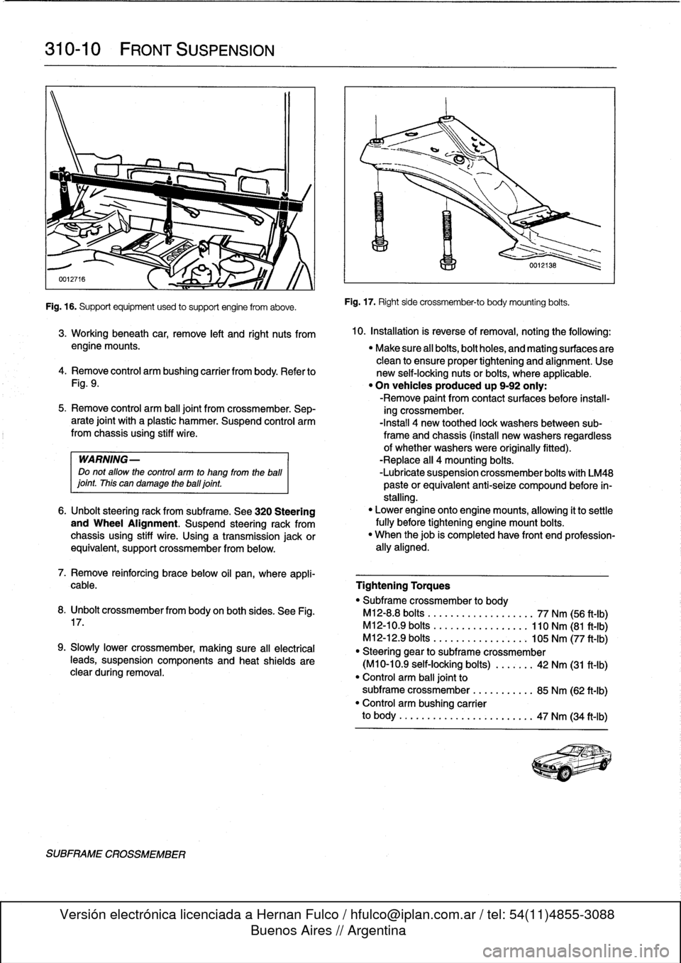
Fig
.
16
.
Supportequipment
used
to
support
engine
from
aboye
.
SUBFRAME
CROSSMEMBER
Fig
.
17
.
Right
side
crossmember-to
body
mounting
bolts
.
3
.
Working
beneath
car,
remove
left
and
right
nuts
from
10
.
Installation
is
reverse
ofremoval,
noting
the
followíng
:
engine
mounts
.
"
Make
sure
all
bolts,bolt
holes,
and
mating
surfaces
are
clean
to
ensure
proper
tightening
and
alignment
.
Use
4
.
Remove
control
arm
bushing
carrier
from
body
.
Refer
to
new
self-locking
nuts
or
bolts,
where
applicable
.
Fig
.
9
.
"
On
vehicles
produced
up
9-92
only
:
-Remove
paint
from
contact
surfaces
before
ínstall-
5
.
Remove
control
arm
ball
joint
from
crossmember
.
Sep-
ing
crossmember
.
arate
joint
with
a
plastic
hammer
.
Suspend
control
arm
-Install
4
new
toothed
lock
washersbetween
sub-from
chassis
using
stiff
wire
.
frame
and
chassis
(install
new
washers
regardless
of
whether
washers
were
originally
fitted)
.
WARNING-
-Replace
all
4
mounting
bolts
.
Do
not
allow
the
control
arm
to
hang
from
the
ball
-Lubrícate
suspension
crossmember
bolts
with
LM48
¡oint
.
This
can
damage
theball¡oint
.
paste
orequivalent
anti-seize
compound
before
ín-
stalling
.
6
.
Unbolt
steering
rack
from
subframe
.
See
320
Steering
"
Lower
engine
onto
enginemounts,
allowing
it
to
settle
and
Wheel
Alignment
.
Suspend
steering
rack
from
fully
before
tightening
engine
mount
bolts
.
chassis
using
stiff
wire
.
Using
a
transmission
jackor
"
When
thejob
is
completed
have
front
end
profession-
equivalent,
support
crossmember
from
below
.
ally
aligned
.
7
.
Remove
reinforcing
brace
below
oil
pan,
where
appli-
cable
.
Tightening
Torques
"
Subframe
crossmember
to
body
8
.
Unbolt
crossmemberfrom
body
on
both
sides
.
See
Fig
.
M12-8
.8
bolts
..................
.
77
Nm
(56
ft-Ib)
17
.
M12-10
.9
bolts
.................
110
Nm
(81
ft-Ib)
M12-12
.9
bolts
............
.
...
.
105
Nm
(77
ft-Ib)
9
.
Slowly
Lower
crossmember,
making
sure
all
electrical
"
Steering
gear
to
subframe
crossmember
teads,
suspension
components
and
heat
shields
are
(M10-10
.9
self-locking
bolts)
..
.
.
.
.
.
42
Nm
(31
ft-Ib)
clear
during
removal
.
"
Control
arm
balljoint
to
subframe
crossmember
...
.......
.
85
Nm
(62
ft-Ib)
"
Control
arm
bushing
carrier
to
body
..........
...
.
.....
.
..
..
47
Nm
(34
ft-Ib)
Page 268 of 759
320-2
STEERING
AND
WHEEL
ALIGNMENT
3
.
Carefully
remove
airbag
from
front
of
steering
wheel
.
See
721
Airbag
System
(SRS)
.
Store
airbag
unit
in
a
safe
place
.
WARNING-
Improper
handling
of
theaírbag
could
cause
seri-
ous
ínjury
.
Store
theaírbag
with
the
horn
pad
facing
up
.
If
stored
facing
down,
accidental
deployment
could
propel
it
vlolently
into
the
air,
causíng
ínjury
.
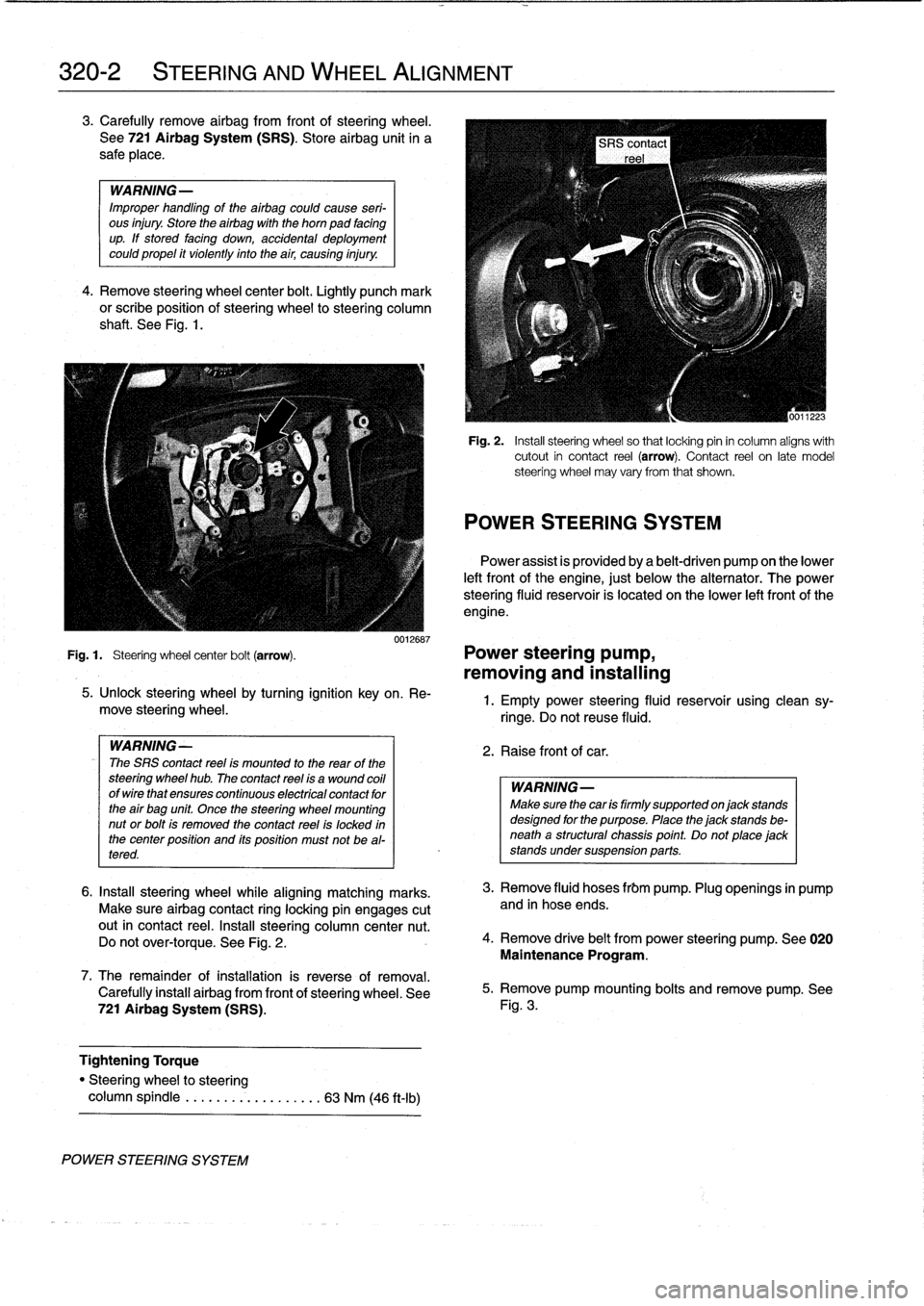
4
.
Remove
steering
wheel
center
bolt
.
Lightly
punch
mark
or
scribe
position
of
steering
wheel
to
steering
column
shaft
.
See
Fig
.
1
.
0012687
Fig
.
1
.
Steering
wheel
center
bolt
(arrow)
.
Power
steering
pump,
removing
and
installing
POWER
STEERING
SYSTEM
5
.
Unlock
steering
wheel
by
turning
ignition
key
on
.
Re-
move
steering
wheel
.
WARNING-
The
SRS
contact
reel
ís
mounted
to
the
rear
of
the
steering
wheel
hub
.
The
contact
reel
ís
a
wound
coil
ofwirethat
ensures
continuous
electrícal
contact
for
the
air
bag
unit
Once
the
steering
wheel
mounting
nut
or
bolt
is
removed
the
contact
reel
is
locked
in
the
center
position
and
its
position
must
not
be
al-
tered
.
6
.
Insta¡¡
steering
wheel
while
aligning
matching
marks
.
Make
sure
airbag
contact
ring
locking
pin
engages
cutout
in
contact
reel
.
Insta¡¡
steering
column
center
nut
.
Do
not
over-torque
.
See
Fig
.
2
.
7
.
The
remainder
ofinstallation
is
reverse
of
removal
.
Carefully
install
airbag
from
front
of
steering
wheel
.
See
721
Airbag
System
(SRS)
.
Tightening
Torque
"
Steering
wheel
to
steering
column
spindle
...
..
..
.
..........
63
Nm
(46
ft-Ib)
Fig
.
2
.
Insta¡¡
steering
wheel
so
that
locking
pin
in
column
aligns
with
cutout
in
contact
reel
(arrow)
.
Contact
reel
on
late
model
steering
wheel
may
vary
from
that
shown
.
POWER
STEERING
SYSTEM
Power
assist
is
províded
by
a
belt-driven
pump
on
the
lower
left
front
of
the
engine,
just
below
the
alternator
.
The
power
steering
fluid
resenroir
is
located
on
the
lower
left
front
of
the
engine
.
1
.
Empty
power
steering
fluid
reservoir
usingclean
sy-
ringe
.
Do
not
reuse
fluid
.
2
.
Raise
front
of
car
.
WARNING
Make
sure
thecar
is
firmly
supportedon
jack
stands
designed
for
the
purpose
.
Place
the
jack
stands
be-
neatha
structural
chassis
point
.
Do
not
place
jack
stands
undersuspension
parts
.
3
.
Remove
fluid
hoses
frbm
pump
.
Plug
openings
in
pump
and
in
hose
ends
.
4
.
Remove
drive
belt
from
power
steering
pump
.
See
020
Maintenance
Program
.
5
.
Remove
pump
mounting
bolts
and
remove
pump
.
See
Fig
.
3
.
Page 269 of 759
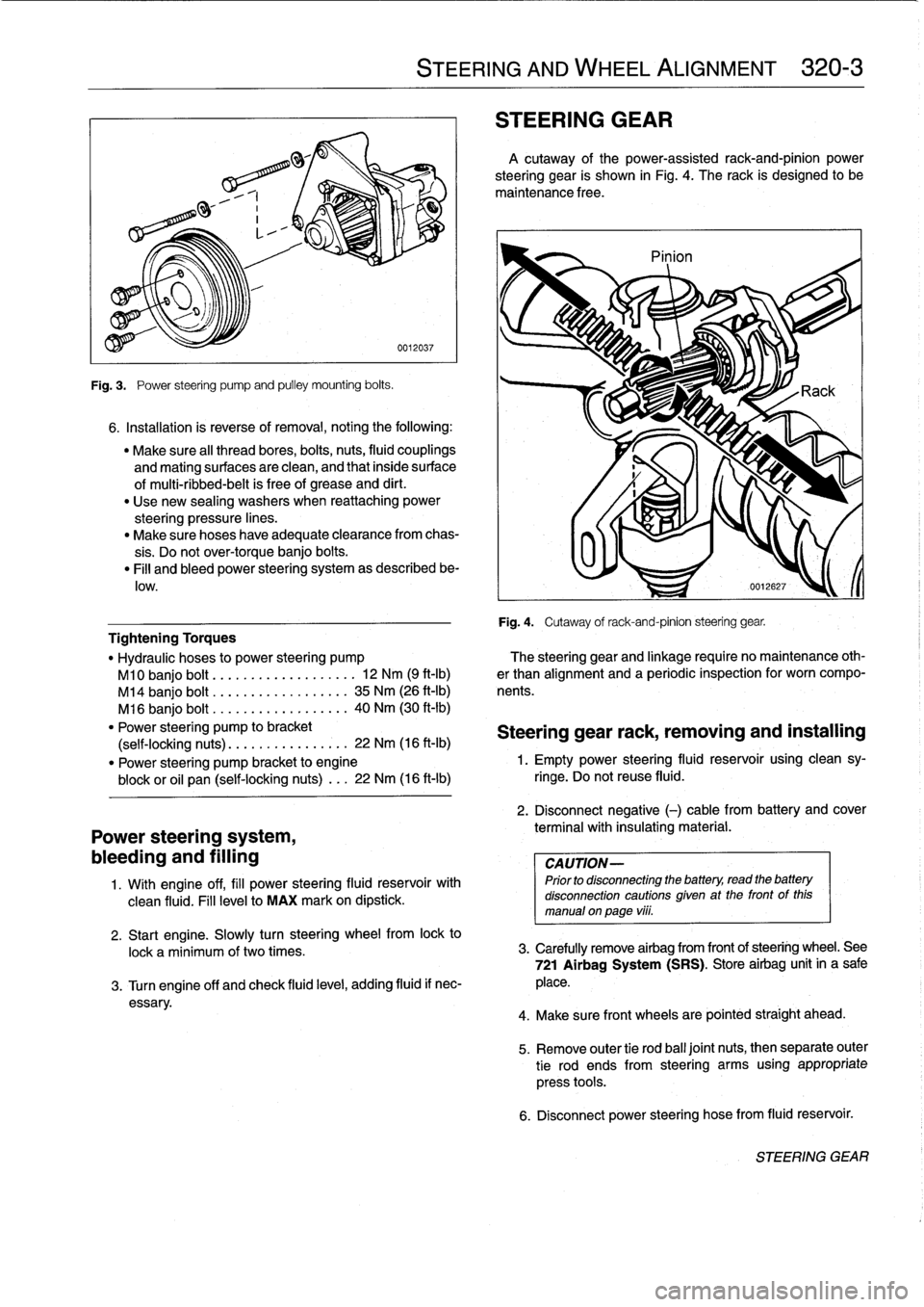
Fig
.
3
.
Power
steering
pump
and
pulley
mounting
bolts
.
6
.
Installation
is
reverse
of
removal,
noting
the
following
:
"
Make
sure
al¡
thread
bores,
bolts,
nuts,
fluid
couplings
and
mating
surfaces
are
clean,
and
that
inside
surface
of
multi-ribbed-belt
is
free
of
grease
and
dirt
.
"
Use
new
sealing
washers
when
reattaching
power
steering
pressure
lines
.
"
Make
sure
hoses
have
adequate
clearance
from
chas-
sis
.
Do
not
over-torque
banjo
bolts
.
"
Fill
and
bleed
power
steering
system
as
described
be-
low
.
Power
steering
system,
bleeding
and
filling
1
.
Wíth
engine
off,
fill
power
steering
fluid
reservoir
with
clean
fluid
.
Fill
levelto
MAX
mark
on
dipstick
.
STEERING
AND
WHEEL
ALIGNMENT
320-
3
STEERING
GEAR
A
cutaway
of
the
power-assisted
rack-and-pinion
power
steering
gear
is
shown
in
Fig
.
4
.
The
rack
is
designed
to
be
maintenance
free
.
Pinion
Fig
.
4
.
Cutaway
of
rack-and-pinion
steering
gear
.
Tightening
Torques
"
Hydraulic
hoses
to
power
steering
pump
?he
steering
gear
and
linkage
require
no
maintenance
oth-
M10
banjo
bolt
.........
..
.
...
...
.
12
Nm
(9
ft-Ib)
er
than
alignment
and
a
periodic
inspection
for
worn
compo
M14
banjo
bolt
..............
..
..
35
Nm
(26
ft-Ib)
nents
.
M16
banjo
bolt
..............
...
.
40
Nm
(30
ft-Ib)
"
Power
steering
pump
to
bracket
Steering
gear
rack,
removing
and
installing
(self-locking
nuts)
.............
..
.
22
Nm
(16
ft-Ib)
"
Power
steering
pump
bracket
to
engine
1
.
Empty
power
steering
fluid
reservoir
using
clean
sy-
block
or
oil
pan
(self-locking
nuts)
...
22
Nm
(16
ft-lb)
ringe
.
Do
not
reuse
fluid
.
2
.
Disconnect
negative
(-)
cable
from
battery
and
cover
terminal
with
insulating
material
.
CAUTION-
Prior
to
disconnectiog
the
battery,
read
the
battery
disconnection
cautions
given
at
the
front
of
this
manual
on
page
viii
.
2
.
Start
engine
.
Slowly
turn
steering
wheelfrom
lock
to
lock
a
minimum
of
two
times
.
3
.
Carefully
remove
airbag
from
frontof
steering
wheel
.
See
721
Airbag
System
(SRS)
.
Store
airbag
unit
in
a
sale
3
.
Turn
engine
off
and
check
fluid
leve¡,
adding
fluid
if
nec-
place
.
essary
.
4
.
Make
sure
front
wheelsare
pointed
straight
ahead
.
5
.
Remove
outer
tie
rod
ball
joínt
nuts,
thenseparate
outer
tie
rod
ends
from
steering
arms
using
appropriate
press
tools
.
6
.
Disconnect
power
steering
hose
from
fluid
reservoir
.
STEERING
GEAR
Page 291 of 759
Brake
rotor,
removing
and
installing
.
.
.
.
.
.
.
.
340-7
MASTER
CYLINDER
............
.
.
.
.
.
.
.340-7
Master
cylinder,
removing
and
installing
.
...
.
340-7
GENERAL
TROUBLESHOOTING
WARNING
-
"
Although
semi-metallic
and
metallic
Brake
friction
materials
in
Brake
pads
or
shoes
no
longer
con-
tain
asbestos,
they
produce
dangerous
dust
.
"
Brake
fluid
is
poisonous,
highly
corrosive
and
dangerous
to
the
environment
Wear
safety
glasses
and
rubber
gloves
when
working
with
Brake
fluid
.
Do
not
siphonBrake
fluid
with
your
mouth
.
Immediately
clean
away
any
fluid
spilled
on
painted
surfaces
and
wash
with
water,
asBrake
fluid
will
remove
paint
.
"
Always
use
new
Brake
fluid
froma
fresh,
un-
opened
container
.
Brake
fluid
will
absorb
mois-
ture
from
the
air
.
This
canlead
to
corrosion
problems
in
the
brakingsystem,
and
will
also
low-
er
the
Brake
fluid's
boiling
point
.
Dispose
of
Brake
fluid
properly
.
"
Do
notreuse
self-locking
nuts,bolts
or
fasteners
.
They
are
designed
to
be
used
only
once
and
may
failif
reused
.
Always
replace
them
with
new
self-
locking
fasteners
.
BMW
E36
models
areequipped
with
vacuum
power-assist-
ed
four-wheel
disc
brakes
with
an
integral
Antilock
Brake
Sys-
tem
(ABS)
.
Single-pistoncalipers
act
on
solid
or
vented
front
rotors
and
solid
rear
rotors
.
A
brake
pad
wear
sensor
for
each
axle
indicates
when
brake
padsneed
replacement
.
The
dual
drum-type
parking
brakesystem
is
integrated
with
the
rear
brake
rotors
.
NOTE-
M3
models
havevented
directional
Brake
rotors
on
the
rearaxle
as
well
ason
the
front
.
340
Brakes
BRAKES
340-1
GENERAL
.
.
.
.
.
.
.........
.
.
.
..........
340-1
BRAKE
BOOSTER
.........
.
.
.
.
.
...
.
.
.
.
340-8
TROUBLESHOOTING
.......
.
......
.
...
340-1
Brake
booster,
removing
and
installing
....
.
.
340-8
PARKING
BRAKE
.
.....
.
...
.
.
.
.....
.
.
.
340-10
BLEEDING
BRAKES
.
.
.
.
.
.
.
.
..........
340-3
Parking
brake,adjusting
.
.
.
.
.
.
.
.
.
.
.....
.
340-10
Pressure
bleeding
brakes
Parking
brake
shoes,
removing
and
installing
.
340-11(except
cars
with
AST)
.
.
.
.
.
.
.
.
.
...
.
.
.
.
.340-3
Parking
Brake
cable,
replacing
.
.
.
.
.
.
.
.
.
.
.
.
340-11
BRAKE
PADS,
CALIPERS,
ANTILOCK
BRAKE
SYSTEM
(ABS)
.
.
.
.340-11
AND
ROTORS
..........
.
.......
.
.
.
.
.
.
.
340-3
ABS
System
Inspection
.
...
.
.......
.
.
.
..
340-12
Brake
pads,
replacing
............
.
.
.
.
.
.
.
340-4
ABS
wheel
speed
sensors,
replacing
.
.
.
.
..
340-12
Brake
caliper,
removing
and
installing
.
..
..
.
340-6
TABLES
a
.
Brake
System
Troubleshooting
.....
...
.
.
.....
.340-2
b
.
Brake
Rotor
Reconditioning
Specifications
.
.....
.340-7
Brakeperformance
is
mainly
affected
by
three
things
:
the
leve¡
and
condition
of
the
brake
fluid,
the
system's
abilíty
to
create
and
maintain
hydraulic
pressure,
and
the
condition
of
the
friction
components
.
Air
in
the
Brake
fluid
will
make
the
Brake
pedal
feel
spongy
during
braking
or
will
increase
the
Brake
pedalforce
required
to
stop
.
Fluid
contaminated
by
moisture
or
dirt
can
corrode
the
system
.
Inspect
the
Brake
fluid
inside
the
reservoir
.
Ifit
is
dirty
or
murky,
or
is
over
a
year
old,
the
fluid
should
be
replaced
.
Visually
check
the
hydraulic
system
startingat
the
master
cylinder
.
To
check
the
function
of
the
master
cylinder
hold
the
brake
pedal
down
hard
with
the
engine
running
.
The
pedal
should
feelsolid
and
stay
solid
.
If
the
pedal
slowly
falls
to
the
floor,
either
the
master
cylinder
is
leaking
internally,
or
fluid
is
leaking
externally
.
If
no
leaks
canbe
found,
the
master
cylin-
der
is
faulty
and
should
be
replaced
.
Check
all
Brake
fluid
lines
and
couplings
for
leaks,
kinks,
chafing
and
corrosion
.
Check
the
Brake
booster
by
pumping
the
Brake
pedal
ap-
proximately
10
times
with
the
engine
off
.
Hold
the
pedal
down
and
start
the
engine
.
The
pedal
should
fa¡¡
slightly
.
If
not,
check
for
any
visiblefaults
before
suspecting
a
faulty
brake
booster
.
Check
for
strong
vacuum
at
the
vacuum
hose
fitting
at
the
booster,
and
check
the
non-retum
valve
for
one-way
flow
.
Worn
or
contaminated
brake
pads
will
cause
poor
braking
performance
.
Oil-contaminated
or
glazed
pads
will
cause
stopping
distances
to
increase
.
Inspect
the
rotors
for
glazing,
discoloration
and
scoring
.
Steering
wheel
vibration
while
braking
at
speed
is
often
caused
by
warped
rotors,
but
can
also
be
caused
byworn
suspension
components
.
TROUBLESHOOTING
Page 392 of 759
610-6
ELECTRICAL
COMPONENT
LOCATIONS
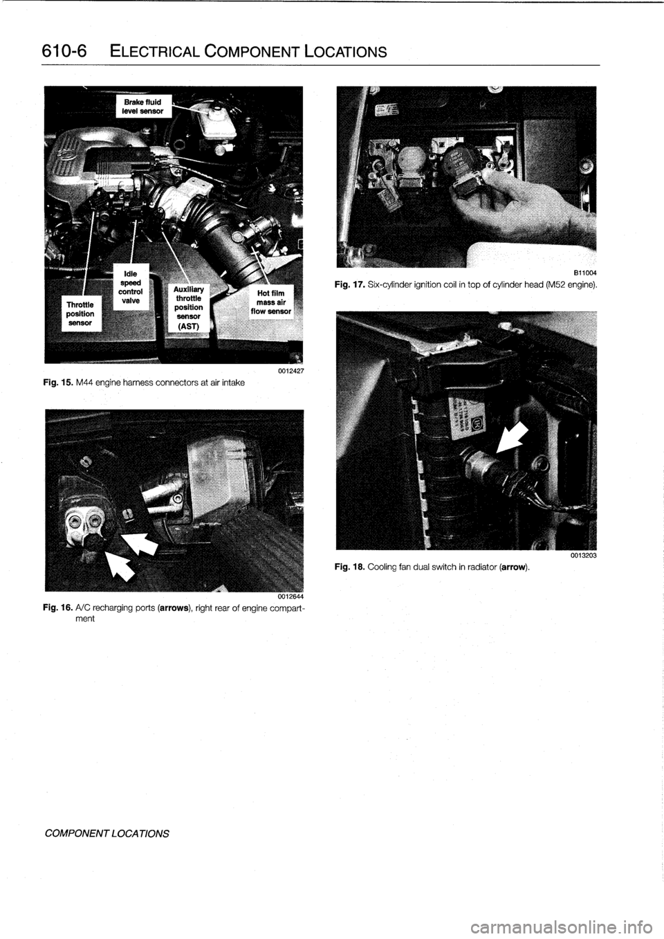
Fig
.
15
.
M44
engine
harness
connectors
atair
intake
0011644
Fig
.
16
.
A/
C
recharging
ports
(arrows),
right
rear
of
engine
compart-ment
COMPONENT
LOCATIONS
0012427
811004
Fig
.
17
.
Six-cylinder
ignition
coil
in
top
of
cylinder
head
(M52
engine)
.
Fig
.
18
.
Cooling
fan
dualswitch
in
radiator
(arrow)
.
0013203
Page 401 of 759
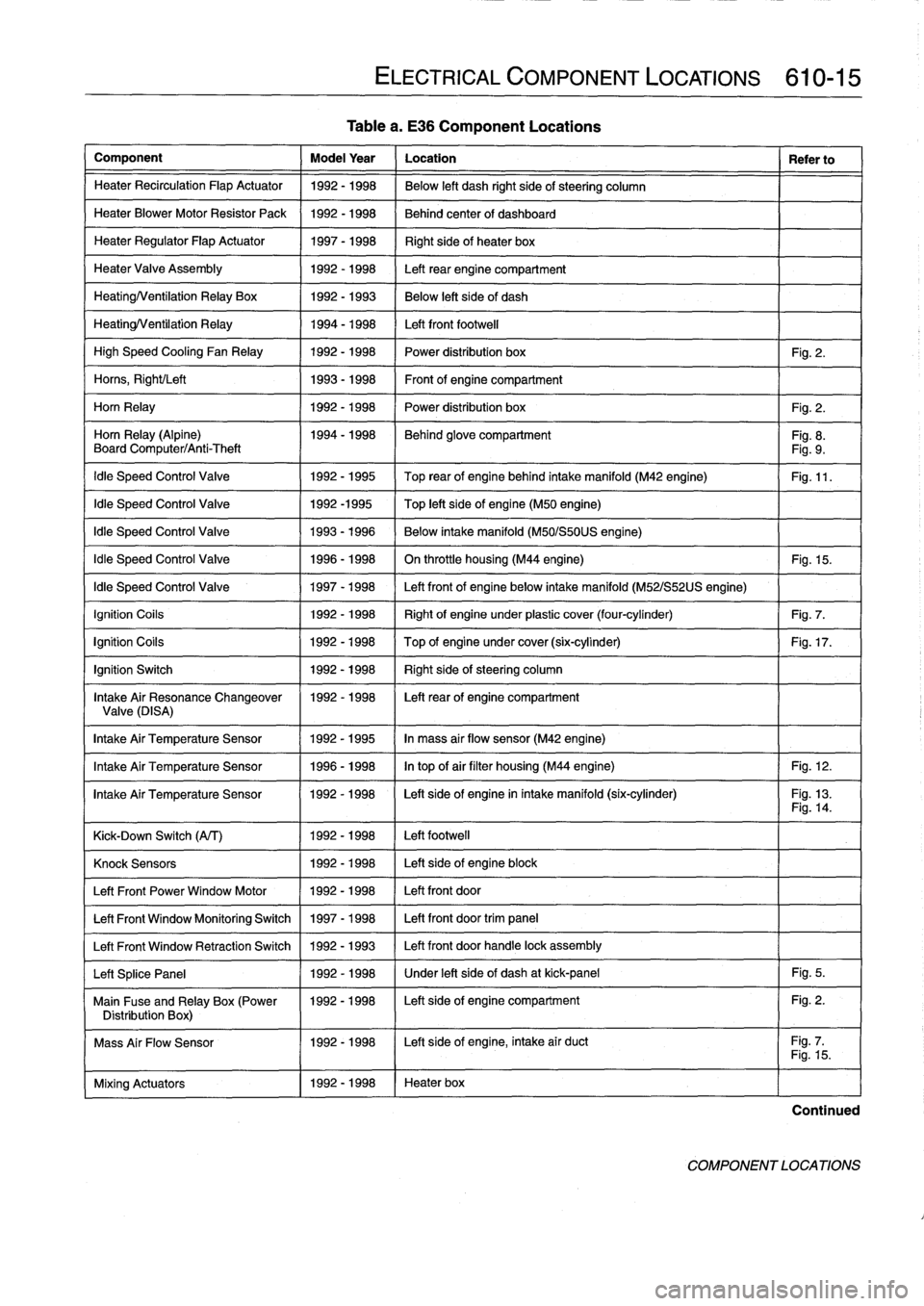
Component
Model
Year
Location
Refer
to
Heater
Recirculation
Flap
Actuator
1992-1998
Below
left
dash
right
side
of
steering
column
HeaterBlowerMotor
Resistor
Pack
1992-1998
Behind
center
of
dashboard
Heater
Regulator
FlapActuator
1997-1998
Right
side
of
heater
box
HeaterValve
Assembly
1992-1998
Left
rear
engine
compartment
HeatingNentilation
Relay
Box
1992-1993
Below
left
side
of
dash
HeatingNentilation
Relay
1994-1998
Left
front
footwell
High
Speed
Cooling
Fan
Relay
1992-1998
Power
distribution
box
Fig
.
2
.
Homs,
Right/Left
1993-1998
Front
of
engine
compartment
Horn
Relay
1992-1998
Power
distribution
box
Fig
.
2
.
Horn
Relay
(Alpine)
1994-1998
Behind
glove
compartment
Fig
.
8
.
Board
Computer/Anti-Theft
Fig
.
9
.
Idle
Speed
Control
Valve
1992-1995
Top
rearof
enginebehind
intake
manifold
(M42
engine)
Fig
.
11
.
Idle
Speed
Control
Valve
1992-1995
Top
left
side
of
engine
(M50
engine)
Idle
Speed
Control
Valve
1993-1996
Below
intake
manifold
(M50/S50US
engine)
Idle
Speed
Control
Valve
1996-1998
On
throttle
housing
(M44
engine)
Fig
.
15
.
Idle
Speed
Control
Valve
1997-1998
Left
front
of
engine
below
intake
manifold
(M52/S52US
engine)
Ignition
Coils
1992-1998
Right
of
engineunder
plastic
cover
(four-cylinder)
Fig
.
7
.
Ignition
Cofs
1992-1998
Top
of
engine
undercover
(six-cylinder)
Fig
.
17
.
Ignition
Switch
1992-1998
Right
sídeofsteering
column
Intake
Air
Resonance
Changeover
1992-1998
Leftrear
of
engine
compartment
Valve(DISA)
Intake
Air
Temperature
Sensor
1992-1995
In
mass
air
flow
sensor
(M42
engine)
Intake
Air
TemperatureSensor
1996-1998
In
top
ofair
filter
housing
(M44
engine)
Fig
.
12
.
Intake
Air
Temperature
Sensor
1992-1998
I
Left
sídeof
engine
in
intake
manifold
(six-cylinder)
-
-
I
Fig
.
13
.
Fig
.
14
.
Kick-Down
Switch
(A/T)
1
1992-1998
1
Left
footwell
Mixing
Actuators
1
1992-1998
1
Heater
box
ELECTRICAL
COMPONENT
LOCATIONS
610-15
Table
a
.
E36
Component
Locations
Knock
Sensors
1
1992-1998
1
Left
side
of
engine
block
Left
Front
Power
Window
Motor
11992-1998
/
Left
front
door
Left
Front
Window
Monitoring
Switch
1
1997-1998
1
Left
front
door
trim
panel
Left
Front
Window
Retraction
Switch
1
1992
-
1993
1
Left
front
door
handle
lock
assembly
Left
Splice
Panel
1
1992-1998
1
Under
left
side
of
dash
at
kick-panel
1
Fig
.
5
.
Main
Fuse
and
Relay
Box
(Power
1992-1998
I
Left
sideof
engine
compartment
Fig
.
2
.
Distribution
Box)
1
I
Mass
Air
Flow
Sensor
1992-1998
I
Left
side
of
engine,
intake
air
duct
Fig
.
7
.1
I
Fig
.
15
.
Continued
COMPONENT
LOCATIONS
Page 402 of 759
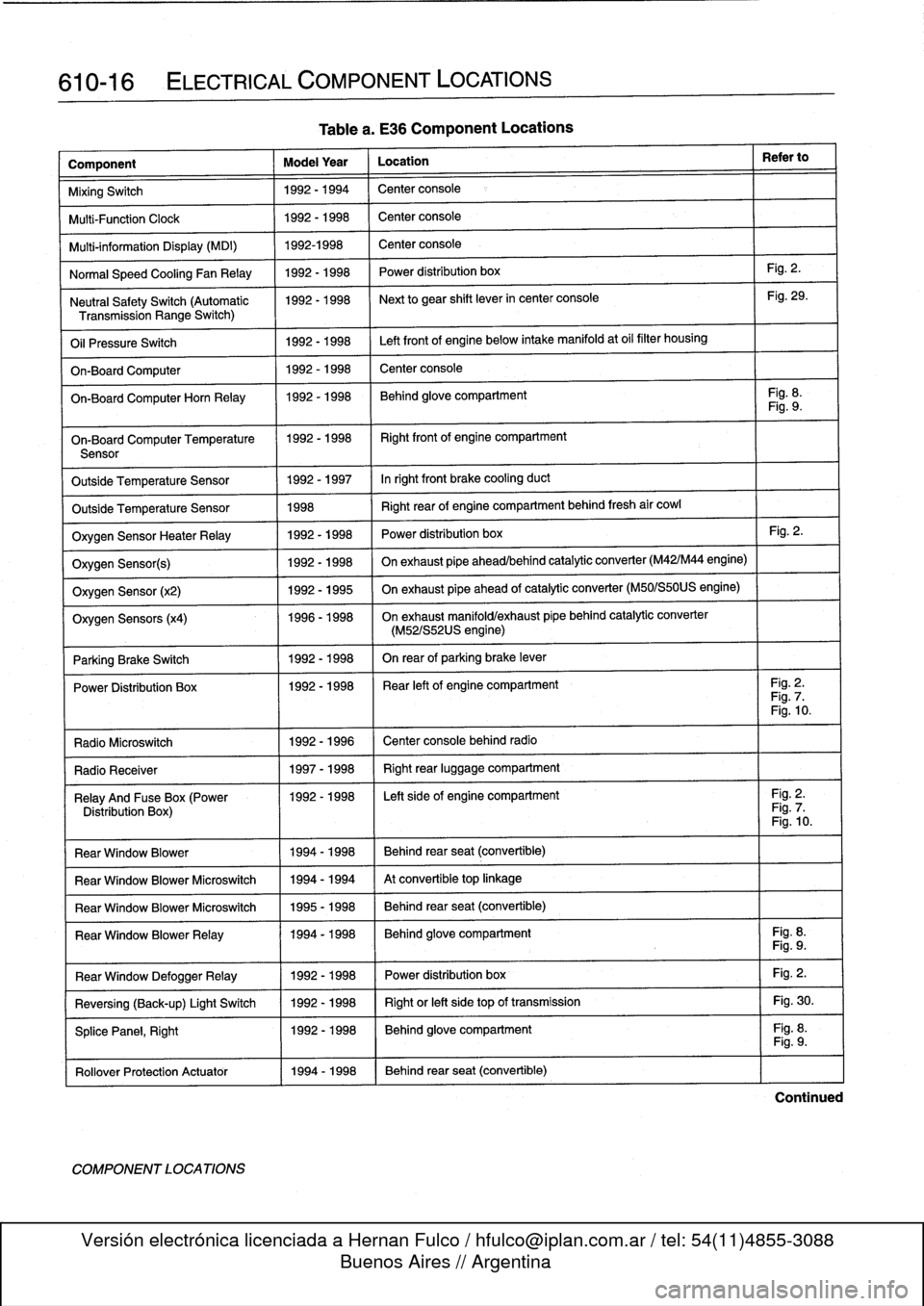
610-16
ELECTRICAL
COMPONENT
LOCATIONS
Component
Model
Year
Location
Refer
to
MixingSwitch
1992-1994
Center
console
Multi-Function
Clock
1992-1998
Center
console
Multi-information
Display
(MDI)
1992-1998
Center
console
Normal
Speed
Cooling
Fan
Relay
1992-1998
Power
distribution
box
Fig
.
2
.
Neutral
SafetySwitch
(Automatic
1992-1998
Next
to
gear
shift
lever
in
center
console
Fig
.
29
.
Transmission
Range
Switch)
Oil
Pressure
Switch
1992-1998
Left
front
of
engine
below
intake
manifold
at
oil
filter
housing
On-Board
Computer
1992-1998
Center
console
On-BoardComputerHorn
Relay
1992-1998
Behind
glove
compartment
Fig
.
8
.
Fig
.
9
.
On-Board
Computer
Temperature
11992-1998
I
Right
front
of
engine
compartment
Sensor
Outside
Temperature
Sensor
1992-1997
Inright
front
brake
cooling
duct
Outside
Temperature
Sensor
1998
Right
rear
of
engine
compartment
behind
fresh
air
cowl
Oxygen
Sensor
HeaterRelay
1992-1998
Power
distribution
box
Fig
.
2
.
Oxygen
Sensor(s)
1992-1998
On
exhaust
pipe
ahead/behind
catalytic
converter
(M42/M44
engine)
Oxygen
Sensor
(x2)
1992-1995
On
exhaust
pipe
ahead
of
catalytic
converter
(M50/S50US
engine)
Oxygen
Sensors
(x4)
1996-1998
On
exhaust
manifold/exhaust
pípe
behind
catalytic
converter
(M52/S52US
engine)
Parking
Brake
Switch
1
1992-1998
I
On
rear
of
parking
brake
lever
Power
Distribution
Box
11992-1998
I
Rear
left
of
engine
compartment
I
Fig
.
2
.
Fig
.
7
.
Fig
.
10
.
Radio
Microswitch
1992
-
1996
Center
console
behind
radio
Radio
Receíver
1
1997-1998
1
Right
rear
luggage
compartment
Relay
And
Fuse
Box
(Power
1992-1998
I
Left
side
of
engine
compartment
I
Fig
.
2
.
Distribution
Box)
Fig
.
7
.
Fig
.
10
.
Rear
Window
Blower
1994-1998
Behind
rear
seat
(convertible)
Rear
Window
Blower
Microswitch
1994-1994
At
convertible
top
linkage
Rear
Window
Blower
Microswitch
1995-1998
Behind
rear
seat
(convertible)
Rear
Window
BlowerRelay
11994-1998
Behind
glove
compartment
Fig
.
8
.
Fig
.
9
.
Fig
.
2
.
Fig
.
30
.
Fig
.
8
.
Rear
Window
DefoggerRelay
Reversing
(Back-up)
Light
Switch
SplicePanel,
Right
Rollover
Protection
Actuator
11994-1998
COMPONENT
LOCATIONS
Table
a
.
E36
Component
Locations
1992-1998
1992-1998
1992-1998
Power
distribution
box
Right
or
left
side
top
of
transmission
Behind
glove
compartment
Behind
rear
seat
(convertible)
Fig
.
9
.
Continued