engine oil BMW 328i 1995 E36 Workshop Manual
[x] Cancel search | Manufacturer: BMW, Model Year: 1995, Model line: 328i, Model: BMW 328i 1995 E36Pages: 759
Page 585 of 759
DATA
LINK
CONNECTOR
1$
,A
WHTT/VIO
COMPUTER
DATA
1~
'
LINES
SYS7EM
1
WH7/~
"
8
R1/
.
.N
r
EGSWARNINGLJ
INSTRUMENTLLUSTER
%16
1
VIO
SHIFT
LK
SOL
AUTO
MODE
SI
G
89077
~\3
IG7IMINGIN7
14
BRN/GRV
HOTATALL
TIMES
r
~
Ea
r
I
~
I
-
"
(
JUNCTION
L
L
JFOIN7
ELECTRICAL
WIRING
DIAGRAMS
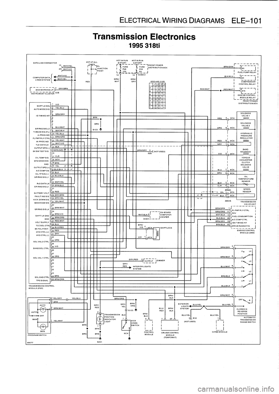
ELE--101
Transmission
Electronics
1995
318ti
HOTINRUNHOTINRUN&START&START
r
FUSE
I
~
F28
L3r-
0
-__
2
I
16
FRONT
POWER
F
ELS
28
E
(DISTRIBUTION
BOX
'-_J
xLOeLz
GRN/
BEN/
RED
WHTGRV
EGSA4S310R
N
'1
003004
G201
D
0
1010
1
300
11
2
1
0
111
00
1
0
g
GRV/RED
2OUTPUT
_JDIMMER
r'`
0
GRV(
--
I
bi
:
RED
INTERIORLIGHTS
I.c2
L
SYSTEM
~N53
I
4BRN
SOLGNDCTRLI
r
-
q
-
--
BRN/GRN
h
~
85
-
I
FUELPUMPRELAV
I
I
COMPRESSOR
I
CONTROLRELAY
I
"
REOIW
TI
87A
I
-
SOLENOIDSOLENOID
VALVE1
BR
N
"
DEG
S
NCA
SPIN
I
SOLENOID
,8
GRN
B
I
NCA
VA
L
E2
GRRNGSIGL3
BLU/WHT
6723
>-
TIMEASSIG(FL)
9
WH7/BLK
A-PROG
IND
10
YEL/BLU
FLPMPPLYCTRL
11
BRN/GRN
M-PROGIND
12
YELIWNT
RED
9
I
T
.DDATALK
13
WH7/VIO
OUTPUT
SPD
()14
BLK
-fl
----
DRY
1-
BKSWTESTSIG5BRN/GRV
BRN/GRV3
(N
OT
USE
D),10
X0
77
CLR
VIO
2
I
OILTEMP
SIG
SPDSENSSHD
18
NCA
19
BRN
GND
20
YEL
T
-
I
OUTPUTBPD(r)
I
A/CCOMPON
16LK/BLU~-
.'BLU
7
44
I
2BLK
BIN
8
OIL7PSIG(a)
11
1
ELK
3
Ir
NCA
__
.
'27
XB52L
SPEED
'
BATTERYVOLT
e
RED
1
-
-~
VEL
1
NCA
SENSOR
FAULTINDSIG
9GRY/BRN
T
~~
BLK
2
NCA
30
GRV/VEL
y
KICK-DO
WN
SIG
1
I
I
1
1
I
MAN
MODESIG
1
YEL/WHT
X
32
l3
BRN/WHT
_
Ft
GRRNGSIGL4
,34
r
ON-BOARD
I
S
BRNIVIO
WHTIBLK41
COMPUTER
SNIFTLKGND
6
BRN/ORG
J(CENTER
GND
%1071
---
VOLTSUPPLY
7
RED/WHT
TLCSOLCTRL
38
BLU
_j
I
BR
BKPD
N/
-
gBLU/RED
VIO
2
NCA
SHIFT
LOCK
L
POSIT
.
HYDCTRL(a)
40
RED
4
HVDCTRL
1
GRV
(-)
~42
VIO
1
NOASOLVAL2CT
43
GRN
RL
t
%851fi
TRANSMISSION
VALVE
UNIT
BRN/ORG
11~IEL
PMPRLYCTRL
I
~WHT/BLK
.
17,
I
DKV
I
BLK%BLU
QB
IFUELCONSUMPTION
I
BRNIA/OCOMPCTRL
I
IIGNTIMINGINT
GRN/GRY
BRN/WHT
8
BRN/BLK
I
ENGINECONTROL
I
MODULERELAY
BRN
RY/I
l
O
RG
EGHOS
B
f
LU~YEL
ALTO
GRV/
YEL(
I
I
BEN
1
E%L
I
I
'
G
RED
RNIWHT
G
BLU/
/
SYSTEM
CLOSEOIN
G123R
ED
ELK
REVERSE
FRONTP0WER
DISTRIBUTION
BOX
IDRIVERANGEP/N~
-
ENGINECONTROL
MODULE
LOME)
O
~
L3
BLU/-
WHT
1-
20
WHT/VIO
SLKIBLU
-
AUTO
\'~
2,1,
T
TRANSMISSION
BLK(
HNI
BLUIVEL
BLU/VEL
PU
I
>I71UN
I
OFF
POSITION
JJJ/
...
BBLK
S
%1a
1
AUTOMATIC
M
I
D
7
26
TRANSMISSION
AN
INDICATOR
1
YEL/WHT
KICK
LIGHT
I
I
~I
(N
OT
US
ED)
I
I
RAN
GE
SWITCH
GOWNBRN
1
SWITCH
I
II
I
II
"
BRNj
MAN
"
CONTROL
CRU
OL
CHIMEMODULE
NCAPROGRAMSWITCH
BENBRN(
MODULE
MODULE
1
1
(TEMPOMAT)
Page 590 of 759
ELE-106
ELECTRICAL
WIRING
DIAGRAMS
8923
1
EGSASS
3102
LlL2L3L4P
11
0
1
q
1
000N
111
0
D
D
0
0
1
40
011
3
1
0
77
200
1
0
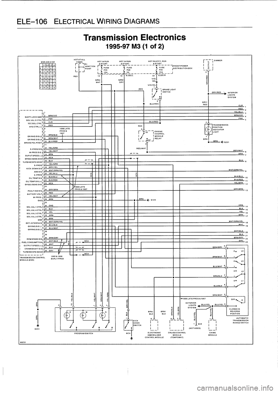
Transmission
Electronics
1995-97
M3
(1
of
2)
HOTATALL
TIMES
HOTINRUNHOTINRUN
HOTINACCV,RUN
.JUNCTION
I
(
POINT
RED
FUSE
FUSE
F26
F2810A
-
--________
-rrr
-
SyK
.1991Z
32
LL,
_
III
NCATRANSMISSION
CONTROL
1995&1998
MODULE(EGS)
EARLVPROD
RED
viol
YELj
VIO/YEL
1
FRONTPOWER
F48
FUSE
DISTRIBUTION
BOX
I
_
11A
____
X19018
SRN/I
BRN(
H
996
LATE
PROD
&
1997
EXTERIOR
I
nrmareNSUMeuaiPTIONuI41
WHT/BLK
Q
NCA
G
RV
I
FUELCO
-
23
I
OUTPUTS
PEED(1)1
42
WHT
ICRANKSHAFTSIGI
43
BLK
-
TURBINESPDSENSI
44
GRY
I
DIMMER
BRAKE
LIGHT
"
r
I
SWITCH
GRVIREO
'~
INTERIOR
LIGHTS
SYSTEM
2
GRV/
"
BILL
IRED
RED
-F,
1
RED
I
I)1
VELSLU
3
I
SHIFT-LOCKGNDI
2
BANIVIO
BAN
VIO
4
I
SOLVALSCTRL
-
I
3
PNKPNK
S
I
TCC
14CLR
BLUIRED
'
2
SOLCTRL
"
I
I
5
RED
RED
TRANSMISSION
HYD
CTRL
(-)
POSITION
I
I
)
1998LATE
g
INDICATOR
I
I)7
P1997ROD&
30
I
C
ENGINE
ONTROL
LIGHT
I
GRRNGSIGL2I
e
BRN/BLK
I
(
MODULE
7
19
BRNIWHT
GRRNGSIGL4
RELAY
I
-
3,87
J
BRN
70
BLU/RED
"
BRN
JI,G201
BRAKE
POL
POST
~IT
)11
S-PROGSIGI
72
YEL/GRN
RED/WHT
M-PROGSIG
1
13
VEL/WHT
14
8114
OUPUTSPEED(-)I
SPEEDSENSSHDI
IS
NCA
-
TURBINESPOSENSI
16
BLU
-
8LU
8
S-PROGI
17
YELIGRN
-
KICK-DOWN
SIGI
i&
GRY/VELABSSIGI
79
WHTIGRN/VEL
WHT/GRN/VEL
9
E-PROGI
20
YEL/BLU
OILTEMPSIGI
21
BLK/BLU
BLK
BLU
10
OIL
TEMP
SIG(
.)(
22
BLK/RED
BLUIRED
it
I
23
NCA
VEL/BRN
12
SPEEDSENSSHDI
4
I
99fi
LATEFAULTINDSIGI)225
GRV/BRN
PROD&7997
26
RED
GRVBRN
13
BATTERVVOLTI
MPROG
27
VEL/WNT
ONOI
28
BRN
"
BRN
G123
I)
SOLVALICTRLI
30
ORG
ORG
14
SOLVAL,CTRLI
31
BLK
BL
.
15
SOLVAL3CTRLI
32
VEL
VEL
7B
SOLVAL2CTRLI
33
GRN
GRN
17GNOI34
BRN
DKT-INTERFACE(
35
WNT/GRN/YEL
WHT/ORN/VEL
1S
GRRNGSIGL1I
36
SLUIBLK
WHT137
BLU/WHT
19
GRRNGSIGL3
138
WHT
BLK
2D
I1
3g
BLK
21
1
40
BRN/GRV
8RN/GRV
22
PROGRAMSWITCH
NCAI
ELECTRONIC
CRUISECONTROL
CHIME
IMMOBILIZER
MODULE
MODULE
1
CONTROLMODULE
(TEMPOMAT)
GRN/WHT
2
RED/-T
S
SRN
7
J
'
CLOSEDIN
REVERSE
BLK
(
BLK
m
I
w
I
w
I
~,I
I
POSITION
r~,Ba
&
START
&START
&START
r_______,______________
AUTOMATIC
KICK
TRANSMISSION
DOWN
III
I
I
RANGESWITCH
SWITCH
II
I
I
Xt4
III
___
I
(NOTUSED)
I
-
Page 592 of 759
ELE-108
ELECTRICAL
WIRING
DIAGRAMS
10885
8
EGSA5S310Z
Li
L2
L3
L4
P
11
0
1
R
1
000
N
111
0D00
01
400
11
3
1
0
11
200
1
0
I)
1
SHIFT-LOCK
ONO
I
2
SOLVALSCTRLI
3
'C'S0
CTRLI
4
C=R/WHT
HYDCTRL
5
RED
1-)
1
OR
RNGSIGL21
B
I
g
BRNIWHT
GRRNGSIGL41~
BRAKEPDLPOSITI
10
BLU/RED
)11
I
S-PROG
SIG(
12
M-PROG
SIG
113YEL/I=HT
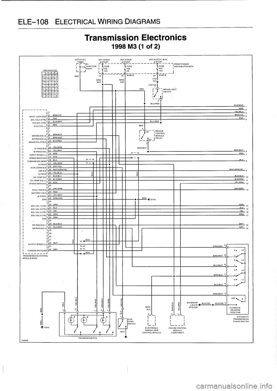
Transmission
Electronics
1998
M3
(1
of
2)
HOTATALL
HOTINRUNHOTINRUN
HOTINACCY,RUN
TIMES
&START
&START
&START
r
,B~
___--
FRONTPOWER
I
M
JUNCTION
FUSE
FUSE
FUSE
I
DISTRIBUTION
BOX
(
POINT
I
F2fi
F28
F46
I
I-
J
__A_----
-A---__----
D
(
12
1
tfi
Y
x1001-Z
32
1
X9
078
GRN(
WHT
GRN/
DRY
VIO/I
YEL
"
VIO/YELj
1
RED
BRAKELIGHT
117
SWITCH
I_`_
1
.J
"
BLUIRE2DY
I
2TTT
RED/WHT
I
mmmmmmm
1®1
"
IIII
H
N~MMNNNNE
L
o~~~m
RED(
B
7
.--t
CONTROL
~
.B7
ENGINE
J
MODULE
RELAY
"
REC/WHT
8B
RN
7
)I
14
BF
.
OUPUTSPEED(-
SPEEDSENSSHD
15
NCA
I
TURBINESPDSENSI
1fi
BLU
-
BLU
8
S-PROGI
17
YEL/GRN
KICK-DOWNSIGI
18
GRYIYEL
I
19
WHT/GRN/YEL
WHT/GRN/YEL
g
E-PROGI
20
YELIBLU
"
<
OIL
121
BLKIBLU
BLKIBLU
TEMP
SIG
10
OILTEMPSIG()I
22
BLK/RED
DLK/RED
11
SPEEDSENSSHDI
27
NCA
VEL/BRN
12
FAULTINDSIGI)21
GRY/BRN
GRY/BRN
13
BATTERY
VOLTI
26
RED
M-PROG
27
YEL/WHT
GNDI
28
BRNIORG
BRN
~I
"
,IG103
I
)29
SOLVAL1CTRLI
30
GAG
ORG
14
SOLVAL4CTRL
I
31
BLK
BLK
15
SOLVAL3CTRLI
32
YEL
YEL
16
SOLVAL2CTRLI
33
GRN
GRN
17
__5,I_
7AI
~
II
I
I
I
ELECTRONIC
CRUISECONTROL
IM
MOBILIZER
MODULECONTROLMODULE
(TEMPOMAT)
GRN/WHT
20
I
EXTERIOR
LIGHTS
14
"
E
-
BRN/
!SYSTEM
CLOSEDIN
mfl
I
T
BLK
REVERSE
POSITION
CLR/WHT
1
RED
2
YELIBLU
3
BRN/VI0
4
PNK
6
R
AUTOMATIC
TRANSMISSION
RANGESWITCH
Page 648 of 759
8299
1
/~
EXCEPT
BRAKE
~J
1997
FLUID
IND
A23
~
.
A16
I
I
SRS
IND
A17
81
18
B
B24
J,
CHARGE
PARK
IND
BRAKE
IND
CHECK
ENGINE
IN.
LEFT
TURN
IND
RIGHT
TURN
IND
1997
ONLY
FUEL
CONSUMPTION
METER
CHECK
IND
SEAT
FRONT
BELT
10
.
LT
INDIND
HIGH
BEAM
IND
FUEL
RESERVE
IND
FUEL
GAUGE
ILL
UM
A22
25
~
(3
USED)
EXCEPT
y
28
7992
TEMPGAUGE
INSTRUMENT
CLUSTER
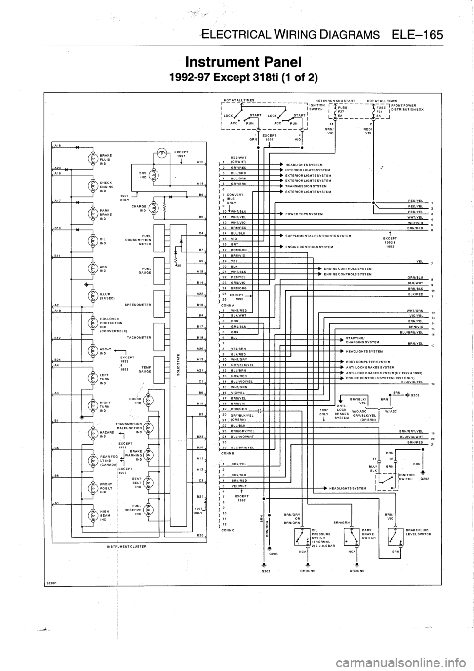
InstrumentPanel
1992-97
Except
318ti
(1
of
2)
B
-ELECTRICAL
WIRING
DIAGRAMS
ELE-165
HOTATALLTIMES
________
HOT
IN
RUNAND
START
HOTATALLTIMES
IGNITION
r
FUSE
FUSE
I
FRONT
UTION
I
(SWITCH
F21
~F31
DISTRIB1000%
LOCK
START
LOCK
START
LL
I
5
_A
_-__-
ACC
RUN
ACC
RUN
14
2
L---
-------
-
-
OR
N1
RED/
T
V
YEL
11
EXCEPT
2
lo
GRN
1997
VIO
RED/WHT
1
(ORWHT)
2
GRYIRED
3
BLU/BRN
4
BLU/GRN
5
GRVIBRN
BS
7
CONVERT-
8
ISLE
ONLY
HEADLIGHTS
SYSTEM
INTERIOR
LIGHTS
SYSTEM
EXTERIOR
LIGHTS
SYSTEM
EXTERIOR
LIGHTS
SYSTEM
TRANSMISSION
SYSTEM
EXTERIOR
LIGHTS
SYSTEM
9
I
iw
.TIBLU
POWERTOPSSYSTEM
11
WHT/YEL
12
WHT/VIO
13
BRN/RED
14
BLU/BLK
15
VIO
16
GRY
-
ENGINE
CONTROLS
SYSTEM
17
BRN/GRN
18
BAN
/Vlo19
YEL
20
BLK
ENGINE
CONTROLS
SYSTEM
A79
21
WHT/BLK
22
RED/YEL
814
23
GRNIVIO
24
BRNIORG
SUPPLEMENTAL
RESTRAINTS
SYSTEM
SPEEDOMETER
816
CONNA
1
WHTIRED
B4
~2
BLK/WHT
ROLLOVER
33
8R~N
PROTECTION
IND
B17
4
GRN/BLU
(CONVERTIBLE)
5
GRIN
TACHOMETER
B18
6
BLU
STARTING/
7
CHARGINGSYSTEM
A20
8
YELIBRN
B
-K/FED
10
WHTIGRY
11
GRYIBLK/YEL
12
BL
LISP
N13
GRN/PED
14
BLU/VIO/YEL
15
WHT/GRN
89
16
VIO/YEL
BRN
"
~I
G202
17
BRNIYEL
GRY/BLK,
BFN
15
18
BN/VIO
VEL
B
ANT
19
BRNIGRN
1997
LOCK
~`r~i
j
W/OASCW/ASO
83
20
GRYIBLK/VEL
ONLY
SYES
4
STEM
GRV/BLK/VEL
21
(ORBRN)
(ORBRN)
22
BLU/BLK
23
BRN/GRV/VEL
BRNIGRVIVEL
19
BRN/GRV
OR
BRN/GRN
HEADLIGHTS
SYSTEM
BODYCOMPUTER
SYSTEM
ANTI-LOCK
BRAKESSYSTEM
ANTI-LOCK
BRAKESSYSTEM
(EX
1992
A1993)
ENGINE
CONTROLS
SYSTEM
(1997
ONLY)
BLU/VIO/YEL
J
EXCEPT
1
.92
.
1993
BIN/
VIO
BRN/GRN
11
OIL
[
._~]
PARK
RA11FL11
AL.^
SWITCH
I
PRESSURE
BRAKE
LEVELSW
U
ITCH
SWITCH
111
G202
GROUND
GROUND
REDIYELRED/YELRED/YEL
WHTIYEL
WHT/VIO
BRN/RED
YEL
GRN/BLU
BLKIWHTBRN/BLK
BLK/RED
WHTIGRN
VIO/YEL
BRNIYELBRN/VIO
BLU/BRNIYEL
BRN/YEL
e9
0
11
1213
141516
Page 649 of 759
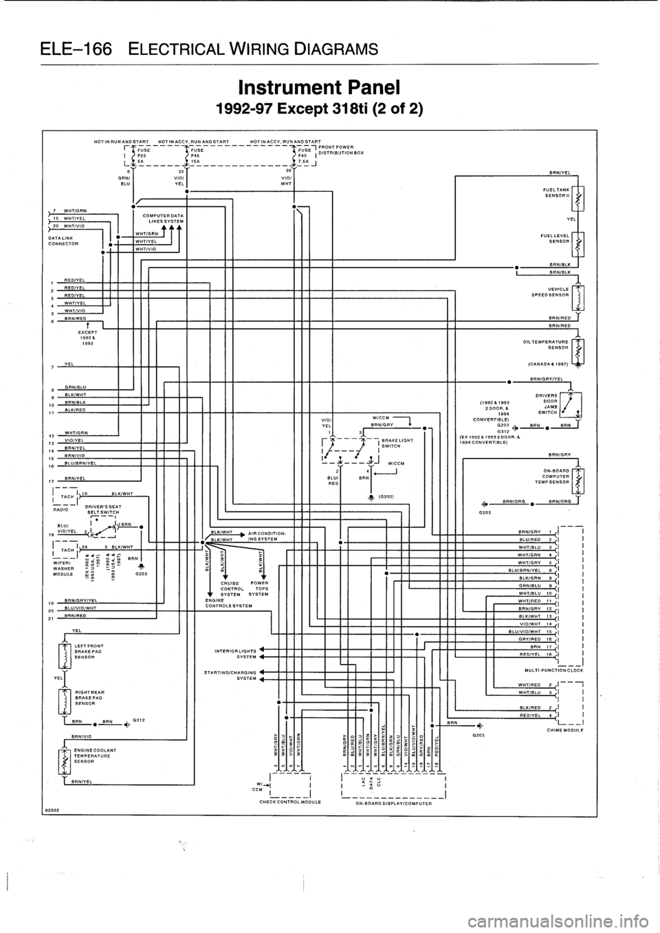
ELE-166
ELECTRICAL
WIRING
DIAGRAMS
"
-
N15
WH7/VA
I
COLIESSSVSTEM
20
WHT/VIO
DATALINK
WHT/GRN
CONNECTOR
WHT/YEL
1
WHT/VIO
REDIVEL
FF"
2
REDIVELREDIVEL
17
BRNIYEL
170
I
TAC-I~
RADIO
DRIVER'SSEAT
BELT
SWITCH
BLUI
I
_
I1
BRN
VIO/YEL
2
I
-
18
19
BRN/GFY/YEL
20
BLU/VIOIWHT
21
BRN/RED
YEL
8299
2
YEL
LEFTFRONT
BRAKEPAD
SENSOR
RIGHT
EAR
BRAKEPAD
SENSOR
HOTINRUNANDSTART
HOTINACCY,PUNANDSTART
HOTINACCY,RUNANDSTART
r
F23
E___
USE
__________-IFFUSE
USE
IDSOTRIBUTIONBOX
BLK/WHT
BRN
"BAN
,I
G312
BRNIVIO
ENGINECOOLANT
TEMPERATURESENSOR
InstrumentPanel
1992-97
Except
318ti
(2
of
2)
5A_____-TISA
____________
.T7
.5AJ
B
32
30Y
GRN/
viol
I
viol
BLU
I
YEL
WHT
WHT/VEL
WHT/VIO
BRNIRED
EXCEPT
1992
&
1993
OIL7EMPESENSOR
7
YEL
(CANADA61997)
.
BRNIGRVIYEL
e
GRNIBLU
9
BLKIWHT
DRIVERS
DOOR
0
JAMB
1994
SWITCH
1
BIN/ILK
(19926
1
993
BLK/RED
2
DOOR,
6
VIOI
WICCM
CONVERT
BR
WHTIGRN
YE'
I
3
N/GRY
~
(EX
1992
6
7993
200
V"'
0R
6
VIO/YEL
I
BRAKELIGHT
.
1990
CONVERTIBLE)
BRNIYEL
SWITCH
BRN/VIO
I
I
8RN/GRV
BLUIBRN/VEL
-
----+-j
W/CCM
.LU/
COMPUTER
REDI
BRN1
~
TEMPSENSOR
MMONE
-
.
INNER
BRNIYEL
I----
I
I--
-
-----
--
W/_I
I
I
CC
M
CHECK
CONTROLMODULE
ON-BOARD
DISPLAYICOMPUTER
BRN
G203
BRNIYEL
FUELTANKI
SENSOR"
FUELLEVEL
SENSORI
8RN/BLK
BRN/BLK
VEHICLE
SPEEDSENSOR
BF
RED
an
RED
YEL
GRN/BLU
9
I
WIT/
WHT/RED
11-I
I
BRNI
.P
Y12
I
I
BLK/WHT
13
I
VIO/WHT
10
I
BLU/VIO/WHT
75
I
GRV/RED
18`
I
I
BRN
17
~I
PEDIYEL
18
I
I
MULTI
FUNCTION
CLOCK
WHTwHTRG1
-
I
WHT/BLU
3
I
II
I
BLKIRED
2
{
I
I
REOIVE
L4
I
I
CHIMEMODULE
Page 652 of 759
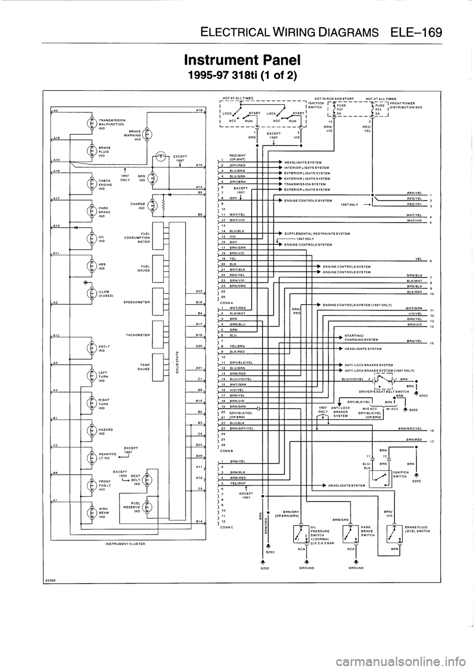
83364
L
J
23
GRN/VIO
-
BLK/WHT
8
24
BRN/ORG
BRNISLK
9
A22
,
25
I
-
BLK/RED
10
26
SPEEDOMETER
B18
CONNA
-
ENGINE
CONTROLS
SYSTEM
(1997
ONLY)
1
WHT/RED
I
'
,,II
I
WHT/GRN
G
REDUI
II
11
VIOIYEL
B4
/
2
BLK/WHT
123
BRN
1
1
11111111
BRN/YEL
13
B77
;
4
GRN/BLU
~ITI
II
IIIIII
BRN/VIO
14
TACHOMETER
818
6
BLU
STARTING/
7
CHARGINGSYSTEM
BRN/YEL
15
A20
6
YEL/8RN
HEADLIGHTSSVSTEM
9
BLK/REO
10
11
GRY/BLK/YEL
ANTI-LOCK
BRAKESSYSTEM
21
12
BLU/BRN
ANTI-LOCK
BRAKESSYSTEM
(1997ONLY)
13
GRN/RED
Cl
14
BLU/VIO/YEL
BLU/VIO/YEL
2LI
\
.I
i
B
L
N
.
II
~
15
WHT/GRN
BRN
16
VIO/YEL
-
-
I
DRIVER'S
SEAT
BELT
SWITCH
j
17
BRNIYEL
.BRN
G203
18
BRN/VIO
GRY/BLK/YEL
BRN
19
BRNIGRN
1997
ANTI-LOCK
W/pqC~
W
j_
p20220
pqy
ONLY
BRAKES
pqy/BLKIVEL
21
(OR
BRN)
SYSTEM
(
r
OR
22
BLU/BLK
23
BRN/GRV/YEL
B
RN/GRY/YEL
.
16
2425
BRN/REO
17
823
.1
28
CONN.
BRN
12
I
I
III
III
_
1
BRN/YEL
BLU/
I
BRN
I
BRN
2
BL
[
BRN/B
I
I
I
IGNITION
3
LK
4
SRN
/RED
,
,SWITCH
G202
5
YEL/WHT
INSTRUMENT
CLUSTER
Instrument
Panel
1995-97
318ti
(1
of
2)
ELECTRICAL
WIRING
DIAGRAMS
ELE-169
HOTATALLTIMES
HOTINRUNANDSTART
HOTATALLTIMES
-~
IGNITION
RRONTPOWER
I
(
SWITCH
r
G27
E
q31
E
I
DISTRIBUTION
BOX
LOCK
START
LOCK
START
i
L
5A
-----
SA_
J
I
ACCRUNACC
RUN
I
14
2
GN/)
REO/
10
EXCEPT
GRN
1997
VIO
V
Y
EL
RED/WHT
1
(ORWHT)
2
GRV/RED
3
BLU/BRN
4
SLUIGRN
5
GAY/BAN
B
EXCEPT
7
1997
8GRY
RED/YEL
ENGINE
CONTROLS
SYSTEM
RED/YEL
1997ONLY
-
"
I
RED/YEL
1011
WHT/YEL
WHTIVEL
4
12
WHT/VIO
WHT/VIO
5
1314
BLU/BLK
SUPPLEMENTAIL
RESTRAINTSSYSTEM
15
V10
ECONTROLS
NGINECOTROLSSYSTEM
17
8RN/GRN
18
BAN/VI0
19
YEL
YEL
B
20
BLK
21
WHT/BLK
ENGINECONTROLSSYSTEM
ENGINECONTROLSSYSTEM
22
RED/YEL
GRN/BLU
7
7
EXCEPT
8
1997
9
10I
V
RN/
I
/
I
B
RNGR
NI
m
I
BRN/GRN
11
(OR
B(N/G
N)81
vio
4
,
12
O
CONNC
I
3I
OIL
PARK
IBRAKEFLUID
LEVEL
SWITCH
/j
/~
PRESSURE
BRAKE
LEVELWITCH
2
SWITCH
V~
SWITCH
7
1)NORMAL
2)
0
.2--BAR
j
G202
HEADLIGHTS
SYSTEM
INTERIORLIGHTS
SYSTEM
EXTERIOR
LIGHTS
SYSTEM
EXTERIOR
LIGHTS
SYSTEM
TRANSMISSION
SYSTEM
EXTERIOR
LIGHTS
SYSTEM
HEADLIGHTS
SYSTEM
.1L
j
GROUND
GROUND
NCAI
NCAI
I
BRN
Page 751 of 759
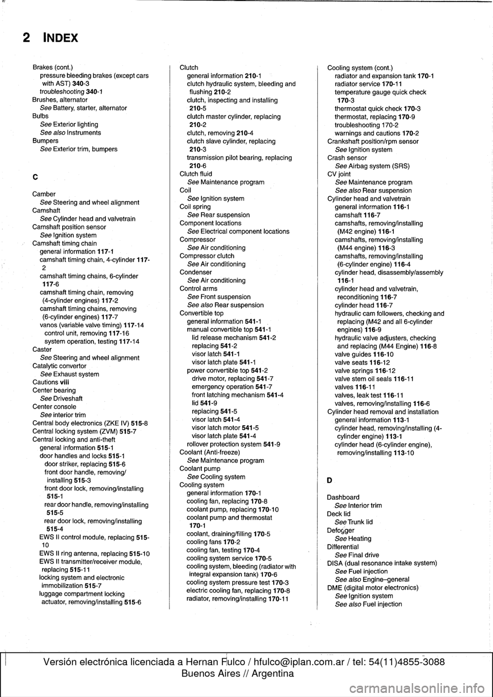
2
INDEX
Brakes
(cont
.)
pressure
bleeding
brakes
(except
cars
wíth
AST)
340-3
troubleshooting
340-1
Brushes,
alternator
See
Battery,
starter,
alternator
Bulbs
See
Exterior
lighting
See
also
Instruments
Bumpers
See
Exterior
trim,
bumpers
C
CamberSee
Steering
and
wheel
alignment
Camshaft
See
Cylinder
head
and
valvetrain
Camshaft
position
sensor
See
Ignition
system
Camshaft
timing
chain
general
information
117-1
camshaft
timingchain,
4-cylinder
117-
2
camshaft
timing
chains,6-cylinder
117-6
camshaft
timing
chain,
removing
(4-cylinder
engines)
117-2
camshaft
timing
chains,
removing
(6-cylinder
engines)
117-7vanos
(variable
valve
timing)
117-14
control
unit,
removing
117-16system
operation,
testing
117-14
Caster
See
Steering
andwheel
alignment
Catalytic
convertor
See
Exhaustsystem
Cautions
viü
Center
bearing
See
Driveshaft
Center
console
See
interior
trim
Central
body
electronics
(ZKE
IV)
515-8
Central
locking
system
(ZVM)
515-7
Centrallocking
and
anti-theft
general
information
515-1
door
handles
and
Iocks
515-1
door
striker,
replacing
515-6
front
door
handle,
removing/
installing
515-3
front
door
lock,
removing/installing
515-1
rear
door
handle,
removing/installing
515-5
rear
door
lock,
removing/installing
515-4
EWS
II
control
module,
replacing
515-10
EWS
II
ring
antenna,
replacing
515-10
EWS
II
transmitter/receiver
module,
replacing
515-11
locking
system
and
electronic
immobilization
515-7
luggage
compartment
locking
actuator,
removing/installing
515-6
Clutch
general
information210-1
clutch
hydraulic
system,
bleeding
and
flushing
210-2
clutch,
inspecting
and
installing
210-5
clutch
master
cylinder,
replacing
210-2
clutch,
removing
210-4
clutch
slave
cylinder,
replacing
210-3
transmission
pilot
bearing,
replacing
210-6
Clutch
fluid
See
Maintenance
program
Coil
See
Ignition
system
Coilspring
See
Rear
suspension
Component
locations
See
Electrical
component
locations
Compressor
See
Air
conditioning
Compressor
clutch
See
Air
conditioning
Condenser
See
Air
conditioningControl
arms
See
Front
suspension
See
also
Rear
suspension
Convertible
top
general
information
541-1
manual
convertible
top
541-1
lid
release
mechanism
541-2
replacing
541-2
visor
latch
541-1
visor
latch
píate
541-1
power
convertible
top
541-2
drive
motor,
replacing
541-7
emergency
operation
541-7
front
latching
mechanism
541-4
lid
541-9
replacing
541-5
visor
latch
541-4
visor
latch
motor541-5
visor
latch
plate
541-4
rollover
protection
system
541-9
Coolant
(Anti-freeze)
See
Maintenance
program
Coolant
pump
See
Cooling
system
Cooling
system
general
information
170-1
cooling
fan,
replacing
170-8
coolant
pump,
replacing
170-10
coolant
pump
and
thermostat170-1
coolant,
draining/filling
170-5
cooling
fans
170-2
cooling
fan,
testing
170-4
cooling
system
service
170-5
cooling
system,
bleeding
(radiator
with
integral
expansion
tank)
170-6
cooling
system
pressure
test
170-3
electric
cooling
fan,
replacing
170-8
radiator,
removing/installing
170-11
Cooling
system
(cont
.)
radiator
and
expansion
tank
170-1
radiator
service
170-11
temperature
gauge
quick
check170-3
thermostat
quick
check
170-3
thermostat,
replacing
170-9
troubleshooting
170-2
warnings
and
cautions
170-2Crankshaft
position/rpm
sensor
See
Ignition
system
Crash
sensor
See
Airbag
system
(SRS)
CV
joint
See
Maintenance
program
See
also
Rear
suspension
Cylinder
head
and
valvetrain
general
information
116-1
camshaft116-7
camshafts,
removing/installing
(M42
engine)
116-1camshafts,
removing/installing
(M44
engine)
116-3
camshafts,
removing/installing
(6-cylinder
engine)
116-4
cylinder
head,
disassembly/assembly
116-1
cylinder
head
and
valvetrain,
reconditioning
116-7
cylinder
head
116-7
hydraulic
cam
followers,
checking
and
replacing
(M42
and
al]
6-cylinder
engines)
116-9
hydraulic
valve
adjusters,
checking
and
replacing
(M44
Engine)
116-8
valve
guides
116-10
valveseats
116-12
valve
springs
116-12
valve
stem
oil
seals
116-11
valves
116-11
valves,
leak
test
116-11
valves,removing/installing
116-6
Cylinder
head
removal
and
installation
general
information
113-1
cylinder
head,
removing/installing
(4-
cylinder
engine)
113-1
cylinder
head
(6-cylinder
engine),
removing/installing
113-10
Dashboard
See
Interior
trim
Deck
lid
See
Trunk
lid
Defogger
See
Heating
Differential
See
Final
drive
DISA
(dual
resonance
intake
system)
See
Fuel
injection
See
also
Engine-general
DME
(digital
motor
electronics)
See
Ignition
system
See
alsoFuel
injection
Page 753 of 759
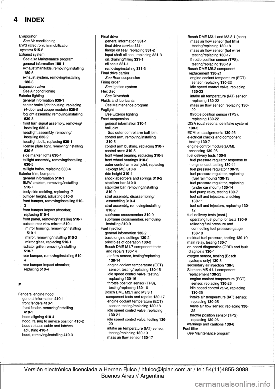
4
INDEX
Evaporator
See
Air
conditioning
EWS
(Electronic
immobilization
system)
515-8
Exhaust
system
See
also
Maintenance
program
general
information
180-1
exhaust
manifolds,
removingAnstalling
180-5
exhaustsystem,
removing/installing
180-3
Expansion
valve
See
Air
conditioning
Exterior
lighting
general
information
630-1
center
brake
light
housing,
replacing
(4-door
and
coupe
models)
630-5
foglight
assembly,
removing/installing
630-3
front
turn
signal
assembly,
removing/
installing
630-4
headlight
assembly,removing/
installing
630-2
headlight
bulb,
replacing
630-1
license
plate
light,
removing/installing
630-6
side
marker
lights
630-4
taillight
assembly,
removing/installing
630-5
taillight
bulbs,
replacing
630-4
Exterior
trim,
bumpers
general
information
510-1
BMW
embiem,
removing/installing
510-7
body
side
molding,
replacing
-7
bumper
height,
adjusting
510-6
front
bumper,
removing/installing
510-3
front
bumper
impact
absorber,
replacing
510-4
front
panel,
removing/installing
510-7
outside
rear
view
mirrors
510-1
mirror
housing,
removing/installing
510-1
mírror,
removing/installing
510-2
mirror
glass,
replacing
510-1
radiator
grille,
removing/installing
510-7
rear
bumper,
removingfinstalling
510-
4
rear
bumper
impact
absorber,
replacing
510-4
F
Fenders,
engine
hood
general
information
410-1
front
fenders
410-1
front
fender,
removing/installing
410-1
hood
aligning
410-4
hood,
raising
to
service
position
410-2
hood
release
cable
and
latches,
adjusting
410-4
hood,
removing/installing
410-3
Finaldrive
general
information
331-1
final
drive
se
rvice
331-1
flange
oil
sea¡,
replacing
331-2
inputshaft
oil
sea¡,
replacing
331-3
oil,
draining/filling
331-1
oil
seals331-1
removing/installing
331-3
Final
drive
carrier
See
Rear
suspension
Firing
order
See
Ignition
system
Flexdisc
See
DriveshaftFluids
and
lubricants
See
Maintenance
program
Foglight
See
Exterior
lighting
Front
suspension
general
information
310-1
ball
joint
See
outer
control
arm
ball
joint
control
arm,
removing/installing
310-5
control
arm
bushing,
replacing
310-7
control
arms
310-5
front
wheel
bearing,
replacing
310-8
front
wheel
bearings
310-8
outer
control
arm
ball
joint,
replacing
(except
M3)310-6
ride
height
310-4shock
absorbers
and
springs
310-2
stabilizer
bar
310-9
stabilizer
bar,
removing/installing
310-9
strut
assembly,disassembling/
assembling310-4
strut
assembly,
removing/installing
310-2subframe
crossmember
310-9subframe
crossmember,
removing/
installing
310-9
Fuel
injection
general
information
130-2
basic
engine
settings
130-2
principies
of
operatínn
130-2
Bosch
DME
Ml
.7
component
tests
and
repairs
130-14
air
floiv
sensor,testing/replacing
130-14
engine
coolant
temperature
(ECT)
sensor,
testing/replacing
130-15
¡dle
speed
control
valve,
testing/
replacing
130-16
throttle
position
sensor
(TPS),
testing/replacing
130-16
Bosch
DME
M3
.1
and
M3
.3
.1
component
tests
and
repairs
130-17
engine
coolant
temperature
(ECT)
sensor,
testing/replacing
130-18
¡dle
speed
control
valve,
replacing
130-21
¡dle
speed
control
valve,
testing
130-
20
intake
air
temperature
(IAT)
sensor,
testing/replacing
130-19
mass
air
flow
sensor130-17
Bosch
DME
M3
.1
and
M3
.3.1
(cont)
mass
air
flow
sensor
(hot
film)
testing/replacing
130-18
mass
air
flow
sensor
(hot
wire)
testing/replacing
130-17
throttle
position
sensor
(TPS),
testing/replacing
130-19
Bosch
DME
M5
.2
component
replacement
130-21engine
coolant
temperature
(ECT)
sensor,
replacing
130-22
ldle
speed
control
valve,
replacing
130-23
intake
air
temperature
(IAT)
sensor,
replacing
130-22
mass
air
flow
sensor,
replacing
130-
22
throttle
position
sensor
(TPS),
replacing
130-22
DISA
(dual
resonance
intake
system)
130-3
ECM
pin
assignments130-26
electrical
checks
andcomponent
testing
130-7engine
control
module(ECM),
accessing
130-26
fuel
delivery
tests
130-9
fuel
pressure
regulator
response
to
engine
load,
testing
130-11
fuel
pressure
regulator
130-13
fuel
pressure
regulator,
replacing
(fuel
rail
mount)130-13
fuel
pressure
regulator,
replacing
(under
car
mount)130-14
fuel
pump
relay,
testing
130-7
fuel
rail
and
injectors,
checking
130-11
fuel
rail
and
injectors,
replacing
130-
12
fuel
delivery
tests
(cont
.)
operatíng
fuel
pump
for
tests
130-9
relieving
fuel
pressure
and
connecting
fuel
pressure
gauge
130-10
residual
fuel
pressure,
testing
130-10
main
relay,
testing
130-7on-board
diagnostics
(OBD)
and
fault
diagnosis
130-4
oxygen
sensor,
testing
(Bosch
systems
only)
130-8
secondary
air
injection
130-5
Siemens
MS
41
.1
component
replacement
130-23
engine
coolant
temperature
(ECT)
sensor,
replacing
130-25
¡dle
speed
control
valve,
replacing
130-26
lntake
air
temperature
(IAT)
sensor,
replacing
130-25
mass
air
flow
sensor,
replacing
130-
25
throttle
position
sensor
(TPS),
replacing
130-26warnings
and
cautions
130-6
Fuel
filter
See
Maintenance
program
Page 754 of 759
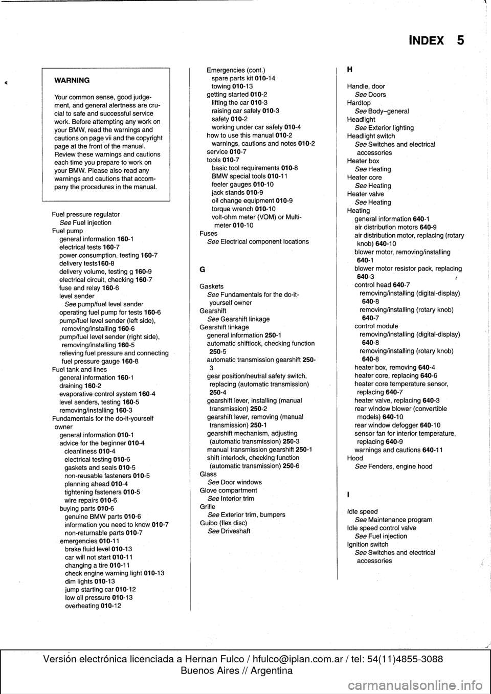
WARNING
Your
common
sense,
good
judge-
ment,
and
general
alertness
are
cru-
cial
tosafe
and
successful
service
work
.
Before
attempting
any
work
on
your
BMW,
read
the
warnings
and
cautions
on
page
vi¡
and
the
copyright
page
at
the
frontof
the
manual
.
Review
these
warnings
and
cautions
each
time
you
prepare
to
work
on
your
BMW
.
Please
also
read
any
warnings
and
cautions
that
accom-
pany
the
procedures
in
the
manual
.
Fuel
pressure
regulator
See
Fuel
injection
Fue]
pump
general
information
160-1
electrical
tests
160-7
power
consumption,
testing
160-7
delivery
tests160-8
delivery
volume,
testing
g
160-9
electrical
circuit,
checking
160-7
fuse
and
relay
160-6
level
sender
See
pump/fuel
leve¡
sender
operating
fuel
pump
for
tests
160-6
pump/fuel
level
sender
(left
side),
removing/installing
160-6
pump/fuel
leve¡
sender
(right
side),
removing/installing
160-5
relieving
fuel
pressure
and
connecting
fue¡
pressure
gauge
160-8
Fueltank
and
lines
general
information
160-1
draining
160-2
evaporative
control
system
160-4
leve¡
senders,
testing
160-5
removing/installing
160-3
Fundamentals
for
the
do-it-yourself
owner
general
information
010-1
advice
for
the
beginner
010-4
cleanliness
010-4
electrical
testing
010-6
gaskets
and
seals
010-5
non-reusable
fasteners
010-5
planning
ahead
010-4
tightening
fasteners
010-5
wire
repairs
010-6
buying
parts
010-6
genuine
BMW
parts
010-6
information
you
need
to
know
010-7
non-returnable
parts
010-7
emergencies
010-11brake
fluid
leve¡
010-13
car
will
not
start
010-11
changinga
tire
010-11
check
enginewarning
light
010-13
dim
Iights
010-13
jump
starting
car
010-12
low
o]I
pressure
010-13
overheating
010-12
Emergencies
(cont
.)
spare
parts
kit
010-14
towing
010-13
gettingstarted
010-2
lifting
thecar
010-3
raising
car
safely
010-3
safety
010-2
working
under
car
safely
010-4
how
to
use
this
manual
010-2
warnings,
cautions
and
notes
010-2
service
010-7
tools
010-7
basic
tool
requirements010-8
BMW
specialtools
010-11
feeler
gauges
010-10
jack
stands
010-9
oil
change
equipment
010-9
torque
wrench
010-10
volt-ohm
meter
(VOM)
or
Multi-
meter010-10
Fuses
See
Electrical
component
locations
G
Gaskets
See
Fundamentals
for
the
do-it-
yourself
owner
Gearshift
See
Gearshift
linkage
Gearshift
linkagegeneral
information
250-1
automatic
shiftlock,
checking
function
250-5
automatic
transmission
gearshift
250-
3
gear
position/neutral
safety
switch,
replacing
(automatic
transmission)
250-4
gearshift
lever,
installing
(manual
transmission)
250-2
gearshift
lever,
removing
(manual
transmission)
250-1
gearshift
mechanism,
adjusting
(automatictransmission)
250-3
manual
transmission
gearshift
250-1
shift
interlock,
checking
function
(automatic
transmission)
250-6Glass
See
Door
windows
Glove
compartment
See
Interior
trim
Grille
See
Exterior
trim,
bumpers
Guibo
(flex
disc)
See
Driveshaft
Handle,
door
See
Doors
Hardtop
See
Body-general
Headlight
See
Exterior
lighting
Headlight
switch
See
Switches
and
electrical
accessoriesHeater
box
See
Heating
Heater
core
See
Heating
Heater
valve
See
Heating
Heating
general
information
640-1
air
distribution
motors
640-9
air
distribution
motor,
replacing
(rotary
knob)
640-10
blower
motor,
removing/installing
640-1blower
motor
resistor
pack,
replacing
640-3
control
head
640-7
removing/installing
(digital-display)
640-8
removing/installing
(rotary
knob)
640-7
control
module
removing/installing
(digital-display)
640-8
removing/installing
(rotary
knob)
640-8
heater
box,
removing640-4
heater
core,
replacing
640-6
heater
core
temperature
sensor,
replacing
640-7
heater
valve,
replacing
640-3
rear
window
blower
(convertible
models)
640-10
reas
window
defogger
640-10sensor
fan
forinterior
temperature,
replacing
640-9warnings
and
cautions
640-11
Hood
See
Fenders,
engine
hood
Idle
speed
See
Maintenance
program
Idle
speed
control
valve
See
Fuel
injection
Ignition
switch
See
Switches
and
electrical
accessories
INDEX
5
Page 755 of 759
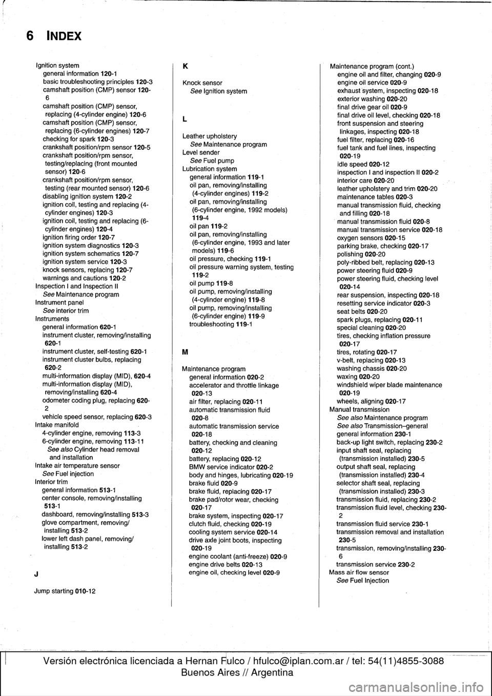
6
INDEX
Ignition
system
general
information
120-1basictroubleshooting
principies
120-3camshaft
position
(CMP)
sensor
120-
6
camshaft
positíon
(CMP)
sensor,
replacing
(4-cylinder
engine)
120-6camshaft
position
(CMP)
sensor,
replacing
(6-cylinder
engines)
120-7
checking
for
spark
120-3
crankshaftposition/rpm
sensor
120-5
crankshaft
position/rpm
sensor,
testing/replacing
(front
mounted
sensor)
120-6
crankshaft
positíon/rpm
sensor,
testing
(rear
mounted
sensor)
120-6
disabling
ignition
system120-2
ignition
coil,
testing
and
replacing
(4-
cylinder
engines)
120-3
ignition
coil,
testing
and
replacing
(6-
cylinder
engines)
120-4
ignítion
firing
order
120-7
ignition
system
diagnostics
120-3
ignition
system
schematics
120-7
ignition
system
service
120-3knock
sensors,
replacing
120-7warnings
and
cautions
120-2
Inspectíon
I
and
Inspection
II
See
Maintenanceprogram
Instrumentpanel
See
interior
trim
Instruments
general
information
620-1
instrument
cluster,
removinglinstalling
620-1
instrument
cluster,
self-testing
620-1
instrument
cluster
bulbs,
replacing
620-2
multi-information
display
(MID),
620-4
multi-information
display
(MID),
removing/installing
620-4
odometer
coding
plug,
replacing
620-
2
vehicle
speed
sensor,
replacing
620-3
Intake
manifold
4-cylinder
engíne,
removing
113-3
6-cylinder
engine,
removing
113-11
See
alsoCylinder
head
removal
and
installation
Intake
air
temperaturesensor
See
Fuel
injection
Interior
trim
general
information
513-1
center
console,
removing/installing
513-1
dashboard,
removing/installing
513-3
glove
compartment,
removing/
installing
513-2
lower
left
dash
panel,
removing/
installing
513-2
J
Jump
startíng
010-12
K
Knock
sensor
See
Ignition
system
L
Leather
upholstery
See
Maíntenance
program
Leve¡
sender
See
Fuel
pump
Lubrication
system
general
information
119-1
oil
pan,
removing/installing
(4-cylinder
engines)
119-2
oil
pan,
removing/installing
(6-cylinder
engine,
1992models)119-4
oil
pan
119-2
oil
pan,
removing/installing
(6-cylinder
engine,
1993
and
later
models)
119-6
oil
pressure,
checking
119-1
oil
pressure
warningsystem,
testing
119-2
oil
pump
119-8
oil
pump,
removing/installing
(4-cylinder
engine)
119-8
oil
pump,
removing/installing
(6-cylinder
engine)
119-9
troubleshooting
119-1
M
Maíntenance
program
general
information
020-2
accelerator
and
throttle
linkage
020-13
air
filter,
replacing
020-11
automatic
transmission
fluid
020-8
automatic
transmission
service
020-18
battery,
checking
and
cleaning
020-12
battery,
replacing
020-12
BMW
service
indicator
020-2
body
and
hinges,
lubricating
020-19
brake
fluid
020-9
brake
fluid,
replacing
020-17
brake
pad/rotor
wear,
checking
020-17
brake
system,
inspecting
020-17
clutch
fluid,
checking
020-19
cooling
system
service
020-14
drive
axle
joint
boots,
inspecting
020-19
engine
coolant
(anti-freeze)
020-9
engine
drive
belts
020-13
engine
oil,
checking
leve¡
020-9
Maintenance
program
(cont
.)
engine
oil
and
filter,
changing020-9engine
oil
service
020-9
exhaust
system,
inspecting
020-18
exterior
washing020-20
final
drive
gear
oil
020-9
final
drive
oil
level,
checking
020-18
front
suspension
and
steering
linkages,
inspecting
020-18
fuel
filter,
replacing
020-16
fuel
tank
and
fuel
lines,
inspecting
020-19
¡dle
speed
020-12
inspection
I
and
inspection
11
020-2
interior
care020-20
leather
upholstery
and
trim
020-20
maintenance
tables
020-3
manual
transmission
fluid,
checking
and
filling
020-18manual
transmission
fluid
020-8
manual
transmission
service
020-18oxygensensors
020-15
parking
brake,
checking
020-17
polishing
020-20
poly-ribbed
belt,
replacing
020-13
power
steering
fluid
020-9
power
steering
fluid,
checking
leve¡
020-14
rear
suspension,
inspecting
020-18
resetting
service
indicator
020-3
seat
belts
020-20
spark
plugs,
replacing
020-11
special
cleaning
020-20
tires,
checking
inflation
pressure
020-17
tires,
rotating
020-17
v-belt,
replacing
020-13
washing
chassis
020-20waxing020-20
windshield
wiperblade
maintenance
020-19
wheels,
aligníng
020-17
Manual
transmission
See
also
Maintenance
program
See
also
Transmission-general
general
information
230-1
back-up
light
switch,
replacing
230-2
inputshaft
sea¡,
replacing
(transmission
installed)
230-5
output
shaftsea¡,
replacing
(transmission
installed)
230-4
selector
shaft
sea¡,
replacing
(transmission
installed)
230-3
transmission
fluid,
replacing
230-2
transmission
fluidlevel,
checking
230-2
transmission
fluid
service
230-1
transmission
removal
and
installation
230-5
transmission,
removing/installing
230-
6
transmission
service
230-2
Mass
air
flow
sensor
See
Fuel
Injection