alternator belt BMW 328i 1995 E36 User Guide
[x] Cancel search | Manufacturer: BMW, Model Year: 1995, Model line: 328i, Model: BMW 328i 1995 E36Pages: 759
Page 141 of 759
2
.
Remove
cooling
duct
or
terminal
cover
from
rear
of
al-
2
.
Remove
air
cleaner
upper
section
with
mass
air
flow
ternator
.
sensor
.
3
.
Check
for
battery
voltage
between
ground
and
terminal
3
.
Remove
terminal
cover
from
rear
of
alternator
.
Discon
B+
at
back
of
alternator
.
Then
turn
ignition
on
and
nect
wiring
.
check
for
battery
voltage
between
terminal
D+
and
ground
.
See
Fig
.
3
.
lf
voltage
is
not
present
at
either
4
.
Remove
drive
belt
from
alternator
pulley
.
See
020
point,
check
wiring
for
faults
.
Maintenance
program
.
001
¡987
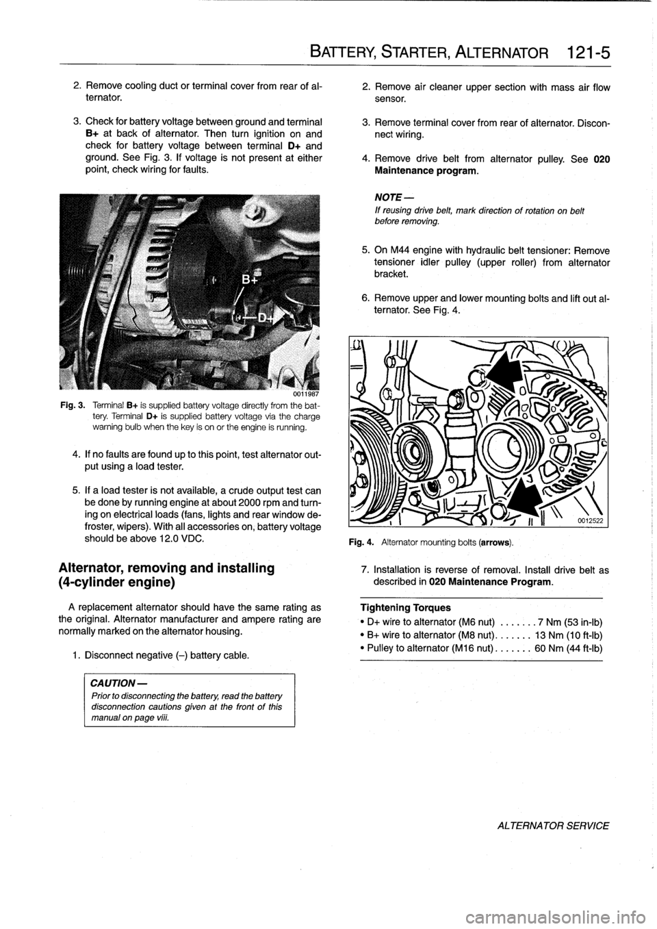
Fig
.
3
.
Terminal
B+
is
supplied
battery
voltage
directly
from
the
bat-
tery
.
Terminal
D+
is
supplied
battery
voltage
via
the
charge
warning
bulb
when
thekey
is
on
or
the
engine
is
running
.
4
.
lf
no
faults
are
foundup
to
thispoint,test
alternator
out-
put
using
a
load
tester
.
5
.
If
a
load
tester
is
not
available,
a
crude
output
test
can
be
done
by
running
engine
at
about
2000
rpmand
turn-
ing
on
electrical
loads
(fans,
lights
and
rear
window
de-
froster,
wipers)
.
With
al¡
accessories
on,
battery
voltage
should
be
above
12
.0
VDC
.
A
replacement
alternator
should
have
the
same
rating
as
the
original
.
Alternator
manufacturer
and
ampere
rating
are
normally
marked
on
the
alternator
housing
.
1
.
Disconnect
negative
(-)
battery
cable
.
CAUTION-
Prior
to
disconnecting
the
battery,
read
the
battery
disconnection
cautions
given
at
the
front
of
this
manual
on
page
vi¡¡
.
BATTERY,
STARTER,
ALTERNATOR
121-
5
6
.
Remove
upper
and
lower
mounting
bolts
and
lift
out
al-
ternator
.
See
Fig
.
4
.
NOTE
-
If
reusing
drive
belt,
mark
direction
of
rotation
on
belt
before
removing
.
5
.
On
M44
engine
with
hydraulic
belt
tensioner
:
Remove
tensioner
idler
pulley
(upper
roller)
from
alternator
bracket
.
Fig
.
4
.
Alternator
mounting
bolts
(arrows)
.
O
u
J
S
v~~
U
I
1
i
n
-12
.22
Alternator,
removing
and
installing
7
.
Installation
is
reverse
of
removal
.
Install
drive
belt
as
(4-cylinder
engine)
described
in
020
Maintenance
Program
.
Tightening
Torques
"
D+
vire
to
alternator
(M6
nut)
.
...
.
.
.
7
Nm
(53
in-lb)
"
B+
wire
to
alternator
(M8
nut)
..
.
.
.
.
.
13
Nm
(10
ft-Ib)
"
Pulley
to
alternator
(M16
nut)
...
..
..
60
Nm
(44
ft-Ib)
ALTERNATOR
SERVICE
Page 142 of 759
121-
6
BATTERY
STARTER,
ALTERNATOR
Alternator,
removing
and
installing
(6-cylinder
engine)
A
replacement
alternator
should
have
the
same
rating
as
the
original
.
Alternator
manufacturer
and
ampere
rating
are
normally
marked
on
the
alternator
housing
.
1
.
Disconnect
negative
(-)
battery
cable
.
CAUTION-
Prior
to
disconnectiog
the
battery,
read
the
battery
disconnection
cautions
given
at
the
front
of
this
manual
onpage
viii
.
2
.
Remove
alternator
cooling
duct
and
air
filter
housing
assembly
from
car
.
Disconnect
wiring
from
rear
of
alter-
nator
.
3
.
Remove
radiator
cooling
fan
and
fan
shroud
.
See
170
Radiator
and
Cooling
System
.
4
.
Remove
alternator
drive
belt
from
alternator
pulley
.
On
engines
with
hydraulic
belt
tensioner,
remove
tensioner
idler
pulley
(upper
roller)
from
alternator
bracket
.
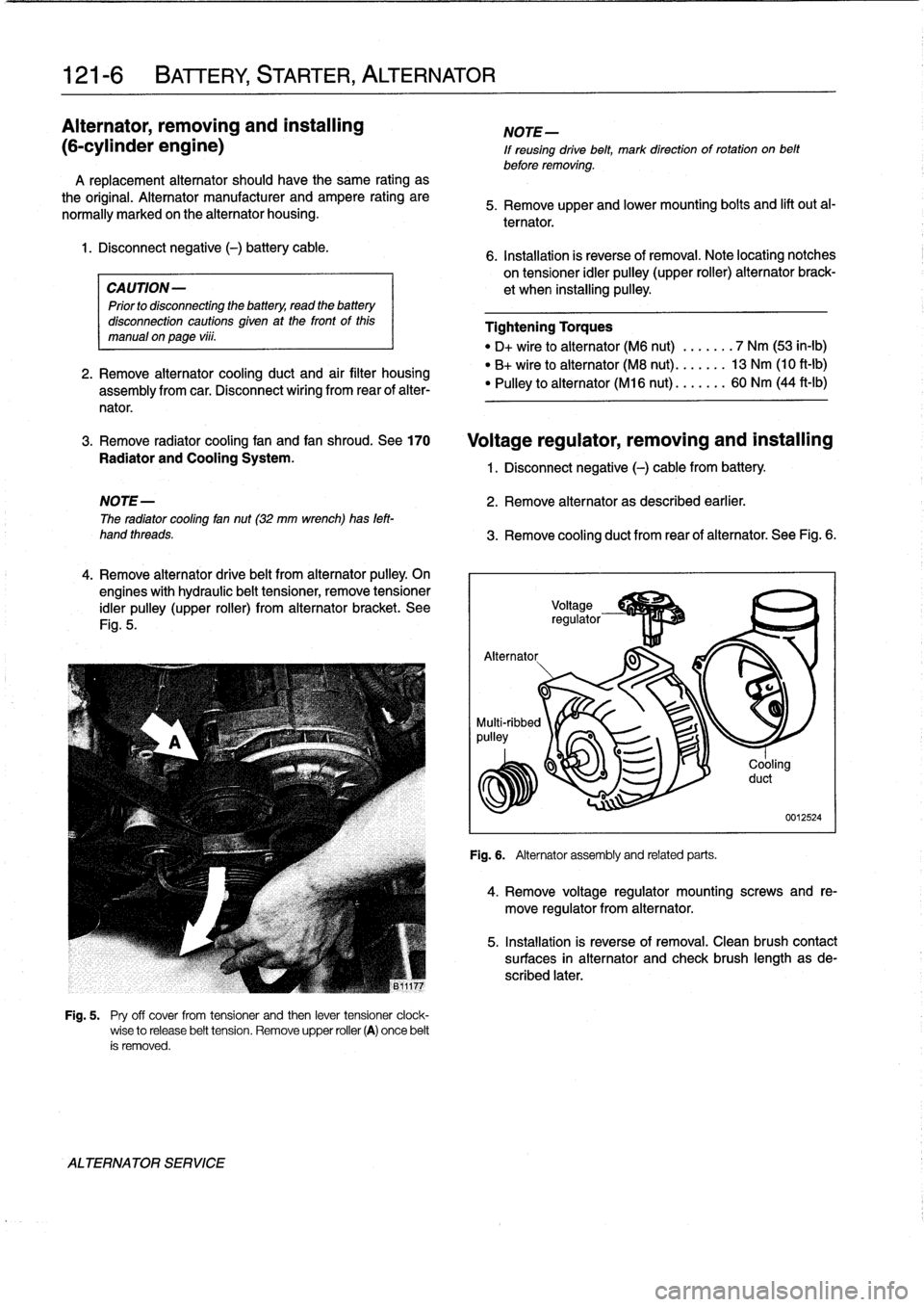
See
Fig
.
5
.
ALTERNATOR
SERVICE
Fig
.
5
.
Pry
off
cover
from
tensioner
and
then
lever
tensioner
clock-
wise
to
release
belt
tension
.
Remove
upper
roller
(A)
once
belt
ís
removed
.
NOTE-
If
reusing
drive
belt,
mark
direction
of
rotation
on
belt
before
removing
.
5
.
Remove
upper
and
lower
mounting
bolts
and
lift
out
al-
ternator
.
6
.
Installation
is
reverse
of
removal
.
Note
locating
notches
on
tensioner
idler
pulley
(upper
roller)
alternator
brack-
et
when
installing
pulley
.
Tightening
Torques
"
D+
wire
to
alternator
(M6
nut)
.......
7
Nm
(53
in-lb)
"
B+
wireto
alternator
(M8
nut)
.......
13
Nm
(10
ft-Ib)
"
Pulley
to
alternator
(M16
nut)
.......
60
Nm
(44
ft-Ib)
Voltage
regulator,
removing
and
installing
1
.
Disconnect
negative
(-)
cable
from
battery
.
NOTE-
2
.
Remove
alternator
as
described
earlier
.
The
radiator
cooling
fan
nut
(32
mm
wrench)has
left-
hand
threads
.
3
.
Remove
cooling
duct
from
rear
of
alternator
.
See
Fig
.
6
.
Alternator
.
.g-
p~
J
-..
.
Fig
.
6
.
Alternator
assemblyand
related
parts
.
Cooling
duct
0012524
4
.
Remove
voltage
regulator
mounting
screws
and
re-
move
regulator
from
alternator
.
5
.
Installation
is
reverse
of
removal
.
Clean
brush
contact
surfaces
in
alternator
and
check
brush
length
asde-
scribed
later
.
Page 268 of 759
320-2
STEERING
AND
WHEEL
ALIGNMENT
3
.
Carefully
remove
airbag
from
front
of
steering
wheel
.
See
721
Airbag
System
(SRS)
.
Store
airbag
unit
in
a
safe
place
.
WARNING-
Improper
handling
of
theaírbag
could
cause
seri-
ous
ínjury
.
Store
theaírbag
with
the
horn
pad
facing
up
.
If
stored
facing
down,
accidental
deployment
could
propel
it
vlolently
into
the
air,
causíng
ínjury
.
4
.
Remove
steering
wheel
center
bolt
.
Lightly
punch
mark
or
scribe
position
of
steering
wheel
to
steering
column
shaft
.
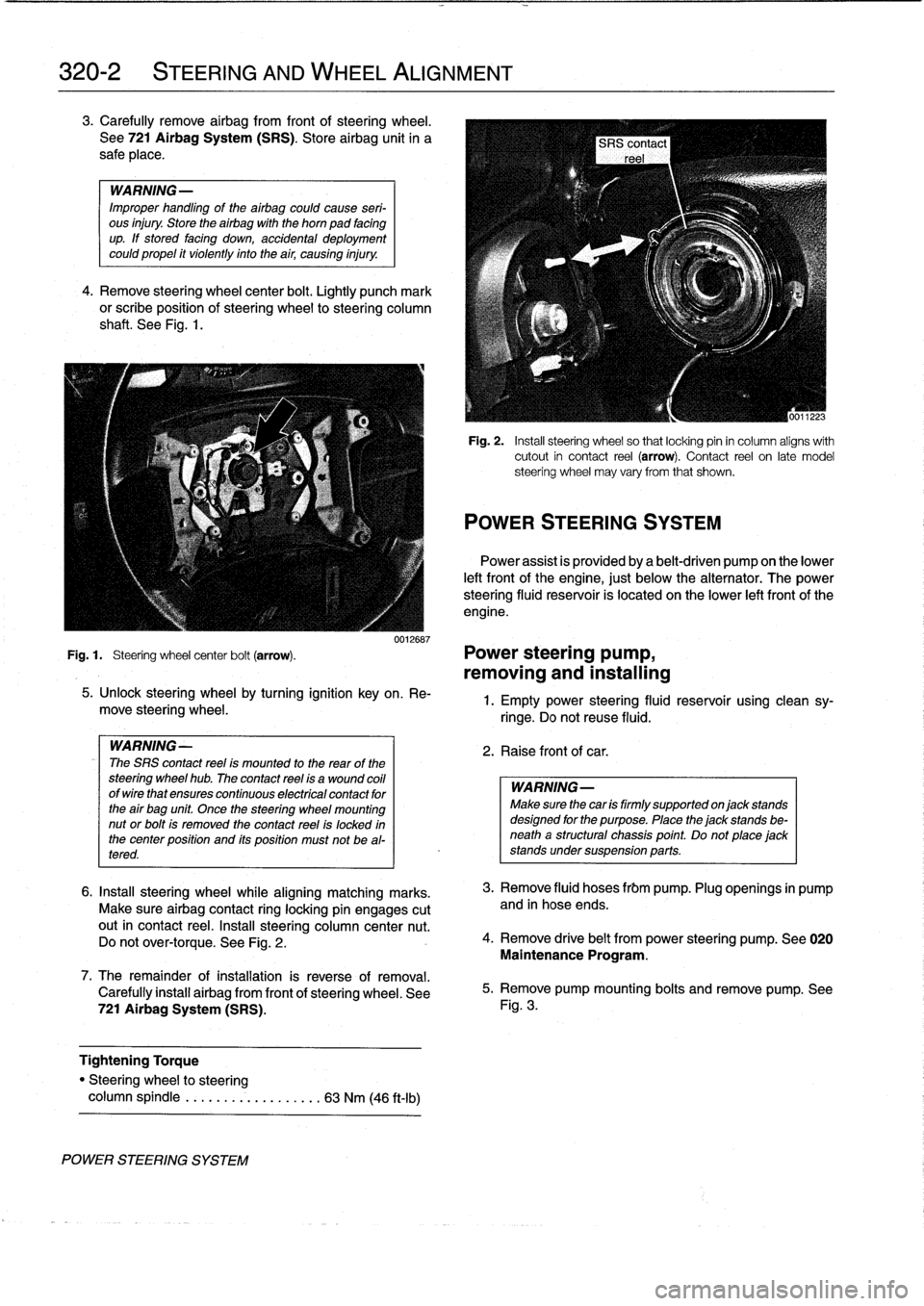
See
Fig
.
1
.
0012687
Fig
.
1
.
Steering
wheel
center
bolt
(arrow)
.
Power
steering
pump,
removing
and
installing
POWER
STEERING
SYSTEM
5
.
Unlock
steering
wheel
by
turning
ignition
key
on
.
Re-
move
steering
wheel
.
WARNING-
The
SRS
contact
reel
ís
mounted
to
the
rear
of
the
steering
wheel
hub
.
The
contact
reel
ís
a
wound
coil
ofwirethat
ensures
continuous
electrícal
contact
for
the
air
bag
unit
Once
the
steering
wheel
mounting
nut
or
bolt
is
removed
the
contact
reel
is
locked
in
the
center
position
and
its
position
must
not
be
al-
tered
.
6
.
Insta¡¡
steering
wheel
while
aligning
matching
marks
.
Make
sure
airbag
contact
ring
locking
pin
engages
cutout
in
contact
reel
.
Insta¡¡
steering
column
center
nut
.
Do
not
over-torque
.
See
Fig
.
2
.
7
.
The
remainder
ofinstallation
is
reverse
of
removal
.
Carefully
install
airbag
from
front
of
steering
wheel
.
See
721
Airbag
System
(SRS)
.
Tightening
Torque
"
Steering
wheel
to
steering
column
spindle
...
..
..
.
..........
63
Nm
(46
ft-Ib)
Fig
.
2
.
Insta¡¡
steering
wheel
so
that
locking
pin
in
column
aligns
with
cutout
in
contact
reel
(arrow)
.
Contact
reel
on
late
model
steering
wheel
may
vary
from
that
shown
.
POWER
STEERING
SYSTEM
Power
assist
is
províded
by
a
belt-driven
pump
on
the
lower
left
front
of
the
engine,
just
below
the
alternator
.
The
power
steering
fluid
resenroir
is
located
on
the
lower
left
front
of
the
engine
.
1
.
Empty
power
steering
fluid
reservoir
usingclean
sy-
ringe
.
Do
not
reuse
fluid
.
2
.
Raise
front
of
car
.
WARNING
Make
sure
thecar
is
firmly
supportedon
jack
stands
designed
for
the
purpose
.
Place
the
jack
stands
be-
neatha
structural
chassis
point
.
Do
not
place
jack
stands
undersuspension
parts
.
3
.
Remove
fluid
hoses
frbm
pump
.
Plug
openings
in
pump
and
in
hose
ends
.
4
.
Remove
drive
belt
from
power
steering
pump
.
See
020
Maintenance
Program
.
5
.
Remove
pump
mounting
bolts
and
remove
pump
.
See
Fig
.
3
.
Page 750 of 759
WARNING
Your
common
sense,
good
judge-
ment,
and
general
alertness
are
cru-
cial
to
safe
and
successful
service
work
.
Before
attempting
any
work
on
your
BMW,
read
the
warnings
and
cautions
on
page
vi¡
and
the
copyright
page
at
the
front
of
the
manual
.
Review
these
warnings
and
cautions
each
time
youprepare
to
work
on
your
BMW
.
Please
also
read
any
warnings
and
cautions
that
accom-
pany
the
procedures
in
the
manual
.
A
ABS
(anti-lock
brakes)
See
Brakes
Accelerator
and
throttle
linkage
See
Maintenance
program
Air
conditioning
general
information
640-1
air
distribution
motor,
replacing
(rotary
knob)
640-10
air
distribution
motors
640-9
blower
motor,
removing/installing
640-1blower
motor
resistor
pack,
replacing
640-3
compressor,
replacing
640-12
compressor
clutch
640-13
condenser,
replacing
640-14
control
head
640-7
removing/installing
(digital
-display)
640-8
removing/installing
(rotary
knob)
640-7
control
module
removing/installing
(digital-display)
640-8
removing/installing
(rotary
knob)
640-8
evaporator,
removinglinstalling
640-17
evaporator
temperature
sensor,
replacing
640-17
expansion
valve,
removing/installing
640-16
microfilter,
replacing
640-18
receiverldrier,
replacing
640-15
sensor
fan
forinterior
temperature,
replacing
640-9
warnings
and
cautions
640-11
Air
distribution
(flap)
motor
See
Air
conditioning
See
also
Heating
Air
filter
See
Maintenanceprogram
Airbag
system
(SRS)
general
information
721-1
contact
ring,
replacing
721-3
driver
side
airbag,removing/installing
721-5
front
crash
sensor,
replacing
721-4
front
side-impact
airbag,
removing/
installing
721-7
front
side-impact
airbag
crash
sensor,
removing/installing
721-5
passenger
side
airbag,
removing/
installing
721-6
sensors
and
electronics
721-1
SRS
warning
light
and
fault
display
721-2
systems
721-1
ZAE
control
module,
replacing
721-5
Alarm
system
See
Central
locking
and
anti-theft
Alternator
See
Battery,
starter,
alternator
Anti-freeze
(Engine
coolant)
See
Maintenance
program
Anti-theft
See
Central
lockíng
and
anti-theft
AST
(Al¡
season
traction)
300-4
ATF
(Automatic
transmission
fluid)
See
Automatic
transmission
Automatic
transmission
See
alsoTransmission-general
general
information
240-1
ATF,draining
and
filling
240-2
ATF
leve¡,
checking
240-1
transmission
removaland
ínstallation
240-4
transmission,
removinglinstalling
240-4
transmission
service
240-1
Auxiliary
fan
See
Cooling
system
Axle
joint
See
Maintenance
program
B
Back-up
light
switch
See
Manual
transmission
Balljoint
See
Front
suspension
Battery
See
Battery,
starter,
alternator
Battery,
starter,
alternator
See
also
Maintenance
program
general
information
121-1
alternator,
removing/installing
(4-
cylinder
engine)
121-5
alternator,
removinglinstalling
(6-
cylinder
engine)
121-6
alternator
brushes,
inspecting/
replacing
121-7
alternator
service
121-4
batterycharging
121-4
battery
load
voltage
test
121-4
batteryopen-circuit
voltage
test
121-4
battery
service
121-3
INDEX
1
Battery,
starter,
alternator
(cont
.)
battery
testing
121-3
charging
system
quick
check121-2
charging
system
troubleshooting
121-
2
hydrometer
testing
121-3
solenoid
switch,
removinglinstalling
121-10
starter
service
121-7
starter
troubleshooting
121-7
starter,
removing/installing(4-cylinder
engine)
121-8
starter,
removing/installing(6-cylinder
engine
with
automatic
transmission)
121-9
starter,
removing/installing
(6-cylinder
engine
with
manual
transmission)
121-8
static
current
draw,
checking
121-2
voltage
regulator,
removing/installing
121-6
Bearing,
wheel
See
Front
suspension
or
Rear
suspension
Blowermotor
See
Air
conditioning
See
also
Heatíng
BMW
emblem
See
Exterior
trim,
bumpers
Body-general
general
information
400-1
body
assembly
400-1
central
body
electronics
400-4
convertible
models
400-2
coupe
models
400-2
electronic
immobilizatíon
system
400-
4
exterior
and
aerodynamics
400-2
heating
afhdair
conditioning
400-5
instruments
and
controls
400-4
interior
equipment
400-3
seats
and
seatbelts
400-3
Body
side
molding
See
Exterior
trim,
bumpers
Brake
fluid
See
Maintenance
program
Brakes
general
information
340-1
antilock
brake
system
(ABS)
340-11
inspection
340-12
wheelspeed
sensors,
replacing
340-12
bleeding
brakes
340-3
brake
booster,
removinglinstalling
340-8
brake
caliper,
removing/installing
340-6
brake
pads,
calipers,
and
rotors
340-3
brake
pads,
replacing
340-4
brake
rotor,
removing/installing
340-7
master
cylinder,
removing/installing
340-7
parking
brake
340-10
adjusting
340-10
.
cable,
replacing
340-11
shoes,
removinglinstalling
340-11
Page 756 of 759
N
WARNING
Your
common
sense,
good
judge-
ment,
and
general
alertness
are
cru-
cial
to
safe
and
successful
service
work
.
Before
attempting
any
workonyour
BMW,
read
the
warnings
and
cautions
on
page
vi¡
and
the
copyright
page
at
the
front
of
the
manual
.
Review
these
warningsand
cautions
each
time
you
prepare
to
work
on
your
BMW
.
Please
also
read
any
warnings
and
cautions
that
accom-
pany
the
procedures
in
the
manual
.
Master
cylinder
See
Brakes
See
also
Clutch
Mechanical
troubleshooting
See
Engine-general
Microfilter
See
Air
conditioning
Mirror
See
Exterior
trim,
bumpers
Muffler
See
Exhaustsystem
Multi-information
display
(MID)
See
Instruments
Neutral
safetyswitch
See
Gearshift
linkage
O
Oil,
changing
See
Maintenance
program
Oil
panSee
Lubrication
system
Oil
pressure
See
Lubrication
system
Oil
pump
See
Lubrication
systemOn-board
diagnostics
(OBD)
See
Engine-general
See
alsoFuel
injection
See
also
Ignition
system
On-board
trip
computer
See
Multi-information
display
620-4
Oxygen
sensor
See
Engine-general
See
alsoFuel
injection
See
also
Maintenance
program
P
Parking
brake
See
Brakes
See
also
Maintenance
program
Parts
See
Fundamentals
for
the
do-it-
yourself
owner
Poly-ribbed
belt
See
Maintenance
program
Power
steering
See
Steering
and
wheel
alignment
Power
steering
(luid
See
Maintenance
program
R
Radiator
See
Cooling
system
Radio
general
information
650-1audio
system
650-1
radio
connector
650-6
removing/installing
650-2speakersdoor
panel
speaker,
removing/
installing
650-5
left
footwell
speaker,
removing/
installing
650-3
rear
speaker,
removing/installing
650-5
right
footwell
speaker,
removing/
installing
650-4Rearsuspension
See
also
Maintenance
program
general
information
330-1
coil
spring,
removing/installing
330-4
CV
boot,
replacing
330-8
drive
axle,
removing/installing
330-6
drive
axles
330-6
final
drive
carrier
330-12
final
drive
carrier,
removing/installing
330-12
lower
control
arm,
removing/installing
330-12
rear
shock
absorber,
removing/
installing
330-3
rear
suspension
arms
330-9
ride
heíght
330-1
shock
absorbers
and
springs
330-2
trailing
arm,
removing/installing
330-10
trailing
arm
bushing,
replacing
330-11upper
control
arm,
removing/installing
330-12
rear
wheel
bearing,
replacing
330-5
rear
wheel
bearings
330-4
Rear
view
mirror
See
Exterior
trim,
bumpers
Receiver/drivr
See
Air
conditioning
Relays
See
Electrical
component
locations
INDEX
7
Ride
height
See
Front
suspension
or
Rearsuspension
Ring
antenna
See
Central
locking
and
anti-theft
Roof
See
Convertible
top
See
also
Sunroof
Roundel
See
Exterior
trim,
bumpers
S
Seat
belts
general
information
720-1
automatic
front
seat
belt
lock
tensioners
720-2
center
rear
lap-belt,
removing/
installing
720-5
front
seat
beltreel,
removing/installing
720-3
mechanical
spring
tensioner,
disarming
720-2
rear
seat
belt,
removing/installing
(fixed
seat
back
models)
720-4
rear
seat
belt,
removing/installing
(fold-down
seat
back
models)
720-5Seats
general
information
520-1
front
seats520-1
manual
front
seat
assembly
520-3
power
front
seat
assembly
520-4
removing/installing
520-1
rear
seats
520-5
rear
seat
cushion
and
backrest,
removing/installing
(fixed
seat
backmodels)
520-5
rear
seat
cushion
and
backrest,
removing/installing
(fold-down
seat
back
models)520-5
rear
seat
backrest
side
section,
removing/installing
(fold-down
seat
back
models)520-6
Shiftinterlock
See
Gearshift
linkage
Shiftlever
See
Gearshift
linkage
Shíftlock
See
Gearshift
linkage
Shock
absorber
See
Front
suspension
See
also
Rear
suspension
Side-impact
airbag
See
Airbag
system
(SRS)
Slave
cylinder
See
Clutch
Service
indicator
See
Maintenanceprogram
Solenoid
See
Battery,
starter,
alternator
Spark
See
Ignition
system
Spark
plugs
See
Maintenance
program
Page 757 of 759
8
INDEX
Speakers
See
Radio
SRS
(Supplemental
restraint
system)
See
Airbag
system
(SRS)
Starter
See
Battery,
starter,
alternator
Steering
and
wheel
alignment
general
information
320-1
caster
and
camber
320-5
front
toe-in
and
toe
difference
angle
320-6
outer
tie
rod
end,
replacing
320-4
power
steering
pump,
removing/
installing
320-2
power
steering
system
320-2
power
steering
system,
bleeding/filling
320-3
rear
toe-in
320-6
steering
gear320-3
steering
gear
rack,
removing/installing
320-3
steering
wheel
320-1
steering
wheel,
removing/installing
320-1
tie
rod,
replacing
320-5
wheel
alignment
320-5
wheel
alignment
specifications
320-6
Steering
gear
See
steering
and
wheel
alignment
Strut
See
Front
suspension
Subframe
See
Front
suspension
Sunroof
general
information
540-1
motor,
removing/installing
540-3
panel,
adjusting
540-2
panel,
emergency
closing
540-2
Suspension,
front
See
Front
suspension
Suspension,
rear
See
Rear
suspension
Suspension,
steering
and
brakes
general
information
300-1
al¡
season
traction
(AST)
300-4
antilock
brake
system
(ABS)
300-2
brakes
300-2
front
suspension
300-1
integrated
systems
300-2
M3
suspension
and
brakes
300-7
steering
300-2
rear
suspension
300-2suspension
and
steering
troubleshooting
300-7
tires
and
wheels300-2
T
Switches
and
electrical
accessories
general
information
612-1
dome
light,
rear
map
lights,
trunk
light,
replacing
bulbs
612-7
hazard
warning
switch,
replacing
612-5
headlight
switch,
replacing
612-5
foglight
switch,
replacing
612-5
ignition
electrical
switch,
replacing
612-3
ignition
lock
cylinder,
replacing
612-4
ignition
switch
assembly
612-3
outside
mirror
switch,
replacing
612-6
power
window
switch,
replacing
612-5
turn
signal
switch
and
wiper
switch,
removing/installing
612-1
wiper
switch
See
turn
signal
and
wiper
switch
Taillight
See
Exterior
lighting
Thermostat
See
Cooling
system
Throttleposition
sensor
(TPS)
See
Fuel
injection
Throw-out
bearing
See
ClutchTierod
See
Steering
and
wheel
alignment
Tires
See
Suspension,
steering
and
brakes-general
See
also
Maintenance
program
Timing
chain
See
Camshaft
timing
chain
Toe-in
See
Steering
and
wheel
alignment
Tools
See
Fundamentals
for
the
do-it-
yourself
owner
Torque
convector
See
Automatic
transmission
Towing
See
Fundamentals
for
the
do-it-
yourself
owner
Traction
control
See
also
Suspension,
steering
and
brakes-general
Trailing
arm
See
Rear
suspension
Transmission-general
See
also
Automatic
transmission
See
also
Manual
transmission
general
information
200-1
automatic
transmission
200-1
manual
transmission
200-1
transmission
ID
codes
200-2
Transmission
fluid
See
Maintenance
program
See
also
Automatic
transmission
Transmission
input
shaft
See
Manual
transmission
Transmission
output
shaft
See
Manual
transmission
Trim,
interior
See
Interior
trim
Trunk
lid
general
information
412-1
trunk
lid,
412-1
trunk
lid,
aligning
412-1
trunk
lid,
removing/installing
412-1
trunk
lid
support
strut,
removing/
installing
412-2
U
Upholstery
See
Maintenance
program
U-joints
See
Driveshaft
V
V-belt
See
Maintenance
program
Vacuum
booster
See
Brakes
Vacuum
leaks
See
Engine-general
Valveguides
See
Cylinder
head
and
valvetrain
Valve
seals
See
Cylinder
head
and
valvetrain
Valveseats
See
Cylinder
head
and
valvetrain
Valves
See
Cylinder
head
and
valvetrain
Valvetrain
See
Cylinder
head
and
valvetrain
VANOS
(variable
valve
timing)
See
Camshaft
timing
chaín
See
also
Engine-general
Vehicle
identification
number
(VIN)
See
Fundamentals
for
the
do-it-
yourself
owner
Vehicle
speed
sensor
See
Instruments
Ventilation
See
Air
conditioning
See
also
Heating
Voltage
regulator
See
Battery,
starter,
alternator
Voltage
tests
See
Electrical
system-general
W
Warnings
vi¡
Washer
fluid
pump
See
Wipers
and
washers
Washers
See
Wipers
and
washers
Water
pump
See
Cooling
system
Waxing
See
Maintenance
program