jack stand BMW 328i 1995 E36 Owner's Manual
[x] Cancel search | Manufacturer: BMW, Model Year: 1995, Model line: 328i, Model: BMW 328i 1995 E36Pages: 759
Page 265 of 759
STABILIZER
BAR
Stabilizer
bar,
removing
and
installing
Stabilizer
bar
link
arrangements
differ
slightly
among
mod-
els
.
In
most
models
the
links
attach
lo
the
control
arms
near
the
outboard
end
.
OnM3
models
the
links
attach
lo
the
strut
assemblies
.
1
.
Raise
car
and
remove
both
front
wheels
.
WARNING
-
Make
sure
that
the
car
is
firmly
supported
on
jack
stands
desígned
for
the
purpose
.
Place
the
jack
stands
beneath
a
structural
chassís
point
.
Do
not
place
jack
stands
under
suspension
parts
.
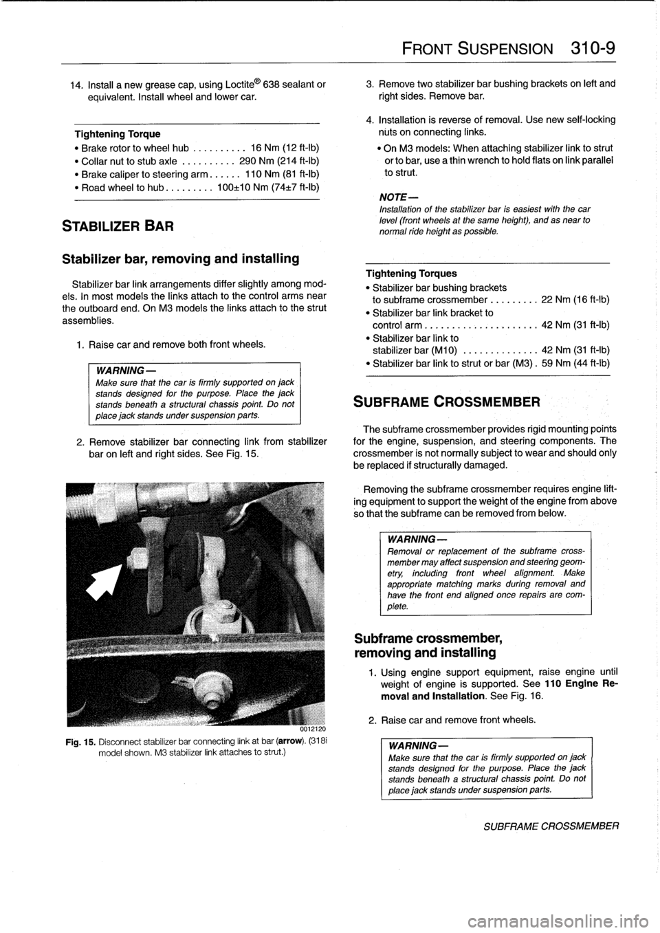
uul
Fig
.
15
.
Disconnect
stabilizer
bar
connecting
link
at
bar
(arrow)
.
(3181
model
shown
.
M3
stabilizer
link
attaches
lo
strut
.)
FRONT
SUSPENSION
310-
9
14
.
Insta¡¡
a
new
grease
cap,
using
Loctite
©
638
sealant
or
3
.
Remove
two
stabilizer
bar
bushing
brackets
on
left
and
equivalent
.
Insta¡¡
wheel
and
lower
car
.
right
sides
.
Remove
bar
.
4
.
Installation
is
reverse
of
removal
.
Use
new
seif-lockíng
Tightening
Torque
núts
on
connecting
links
.
"
Brake
rotor
lo
wheel
hub
..........
16
Nm
(12
ft-Ib)
"
On
M3
models
:
When
attaching
stabilizer
link
lostrut
"
Collar
nut
lo
stubaxle
.
.........
290
Nm
(214
ft-Ib)
orlobar,
usea
thin
wrench
lo
hold
flats
on
link
parallel
"
Brake
caliper
losteering
arm
......
110
Nm
(81
ft-Ib)
lo
strut
.
"
Road
wheel
lo
hub
...
...
.
.
.
100±10
Nm
(74t7
ft-Ib)
NOTE-
Installation
of
the
stabilizer
bar
is
easiest
with
thecar
leve¡
(front
wheels
at
the
same
height),
and
as
near
to
normal
ride
height
as
possible
.
Tightening
Torques
"
Stabilizer
bar
bushing
brackets
lo
subframe
crossmember
...
..
.
..
.
22
Nm
(16
ft-Ib)
"
Stabilizer
bar
link
bracket
lo
control
arm
................
.
.
.
.
.
42
Nm
(31
ft-1b)
"
Stabilizer
bar
link
lo
stabilizer
bar
(M10)
.............
.
42
Nm
(31
ft-Ib)
"
Stabilizer
bar
link
lostrut
or
bar
(M3)
.
59
Nm
(44
ft-Ib)
SUBFRAME
CROSSMEMBER
The
subframe
crossmember
provides
rigid
mounting'poínts
2
.
Remove
stabilizer
bar
connecting
link
from
stabilizer
for
the
engine,
suspension,
and
steering
components
.
The
baron
left
and
right
sides
.
See
Fig
.
15
.
crossmember
is
not
normally
subject
lo
wear
and
should
ohly
be
replaced
if
structurally
damaged
.
Removing
the
subframe
crossmember
requires
engine
lift-
ing
equipment
lo
support
theweight
of
tfhe
engine
from
above
so
that
the
subframe
can
be
removed
from
below
.
WARNING-
Removal
or
replacement
of
the
subframe
cross-
member
may
affect
suspension
and
steering
geom-
etry,
including
front
wheel
afignment
.
Make
appropriate
matching
marks
during
removal
and
have
the
front
end
aligned
once
repairs
are
com-
plete
.
Subframe
crossmember,
removing
and
installing
1
.
Using
enginesupport
equipment,
raise
engine
until
weight
of
engine
is
supported
.
See
110EngineRe-
moval
and
Installation
.
See
Fig
.
16
.
2
.
Raise
car
andremove
front
wheels
.
WARNING-
Make
sure
that
the
car
is
firmly
supportedon
jack
stands
desígned
for
the
purpose
.
Place
the
jack
stands
beneatha
structural
chassís
point
Do
not
place
jack
standsundersuspension
parts
.
SUBFRAME
CROSSMEMBER
Page 268 of 759
320-2
STEERING
AND
WHEEL
ALIGNMENT
3
.
Carefully
remove
airbag
from
front
of
steering
wheel
.
See
721
Airbag
System
(SRS)
.
Store
airbag
unit
in
a
safe
place
.
WARNING-
Improper
handling
of
theaírbag
could
cause
seri-
ous
ínjury
.
Store
theaírbag
with
the
horn
pad
facing
up
.
If
stored
facing
down,
accidental
deployment
could
propel
it
vlolently
into
the
air,
causíng
ínjury
.
4
.
Remove
steering
wheel
center
bolt
.
Lightly
punch
mark
or
scribe
position
of
steering
wheel
to
steering
column
shaft
.
See
Fig
.
1
.
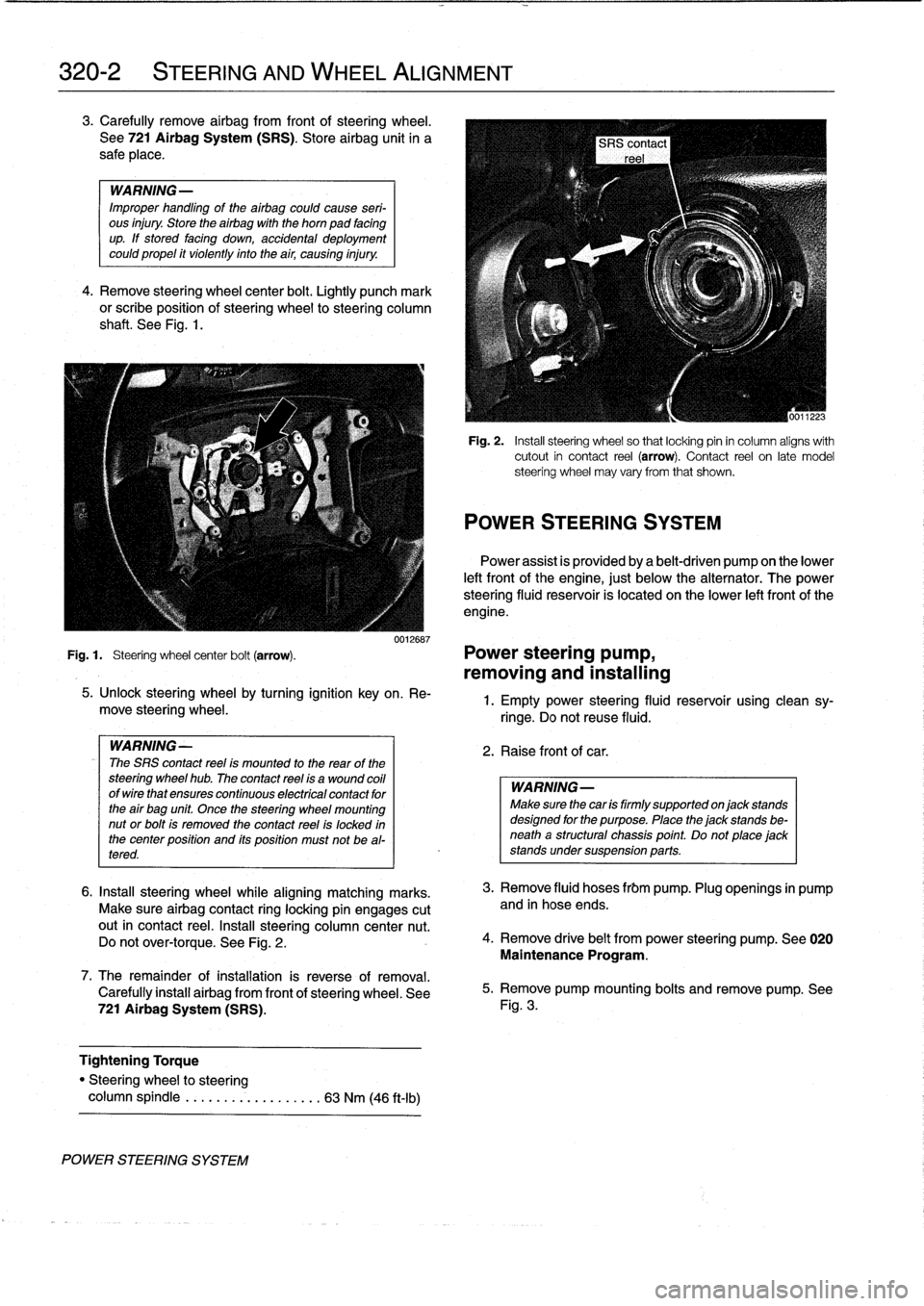
0012687
Fig
.
1
.
Steering
wheel
center
bolt
(arrow)
.
Power
steering
pump,
removing
and
installing
POWER
STEERING
SYSTEM
5
.
Unlock
steering
wheel
by
turning
ignition
key
on
.
Re-
move
steering
wheel
.
WARNING-
The
SRS
contact
reel
ís
mounted
to
the
rear
of
the
steering
wheel
hub
.
The
contact
reel
ís
a
wound
coil
ofwirethat
ensures
continuous
electrícal
contact
for
the
air
bag
unit
Once
the
steering
wheel
mounting
nut
or
bolt
is
removed
the
contact
reel
is
locked
in
the
center
position
and
its
position
must
not
be
al-
tered
.
6
.
Insta¡¡
steering
wheel
while
aligning
matching
marks
.
Make
sure
airbag
contact
ring
locking
pin
engages
cutout
in
contact
reel
.
Insta¡¡
steering
column
center
nut
.
Do
not
over-torque
.
See
Fig
.
2
.
7
.
The
remainder
ofinstallation
is
reverse
of
removal
.
Carefully
install
airbag
from
front
of
steering
wheel
.
See
721
Airbag
System
(SRS)
.
Tightening
Torque
"
Steering
wheel
to
steering
column
spindle
...
..
..
.
..........
63
Nm
(46
ft-Ib)
Fig
.
2
.
Insta¡¡
steering
wheel
so
that
locking
pin
in
column
aligns
with
cutout
in
contact
reel
(arrow)
.
Contact
reel
on
late
model
steering
wheel
may
vary
from
that
shown
.
POWER
STEERING
SYSTEM
Power
assist
is
províded
by
a
belt-driven
pump
on
the
lower
left
front
of
the
engine,
just
below
the
alternator
.
The
power
steering
fluid
resenroir
is
located
on
the
lower
left
front
of
the
engine
.
1
.
Empty
power
steering
fluid
reservoir
usingclean
sy-
ringe
.
Do
not
reuse
fluid
.
2
.
Raise
front
of
car
.
WARNING
Make
sure
thecar
is
firmly
supportedon
jack
stands
designed
for
the
purpose
.
Place
the
jack
stands
be-
neatha
structural
chassis
point
.
Do
not
place
jack
stands
undersuspension
parts
.
3
.
Remove
fluid
hoses
frbm
pump
.
Plug
openings
in
pump
and
in
hose
ends
.
4
.
Remove
drive
belt
from
power
steering
pump
.
See
020
Maintenance
Program
.
5
.
Remove
pump
mounting
bolts
and
remove
pump
.
See
Fig
.
3
.
Page 275 of 759
Rear
shock
absorber,
removing
and
installing
1.
Raisecar
and
remove
rear
wheels
.
WARNING
-
Make
sure
that
thecar
is
firmly
supportedon
jack
stands
designed
for
the
purpose
.
Place
the
jack
stands
beneatha
structural
chassis
point
.
Do
not
place
jack
stands
undersuspension
parts
.
2
.
Remove
rear
speakers
.
See
650
Radio
.
3
.
Pryoutluggage
compartment
liner
retaining
clips
and
peel
back
liner
to
gain
access
to
upper
shock
absorber
mounting
nuts
.
See
Fig
.
3
.
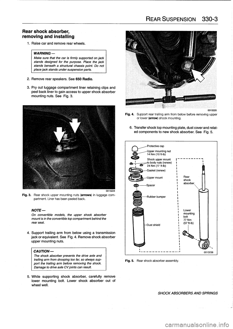
Fig
.
3
.
Rear
shock
upper
mounting
nuts
(arrows)
in
luggage
com-
partment
.
Liner
hasbeen
peeled
back
.
NOTE-
On
convertible
models,
the
uppershock
absorber
mount
is
in
the
convertible
top
compartment
behind
the
rear
seat
.
4
.
Support
trailing
arm
from
below
using
a
transmission
jack
orequivalent
.
See
Fig
.
4
.
Remove
shock
absorber
uppermounting
nuts
.
CAUTION-
The
shock
absorber
prevenís
the
drive
axle
and
trailing
arm
from
drooping
too
far,
so
always
sup-port
the
trailing
arm
before
removing
the
shock
.
Damage
to
drive
axle
CV
joints
can
result
.
0013224
5
.
While
supporting
shock
absorber,
carefully
remove
lower
mounting
bolt
.
Lower
shock
absorber
out
of
wheel
well
.
Fig
.
4
.
Support
rear
trailing
arm
from
below
before
removing
upper
or
lower
(arrow)
shock
mounting
.
6
.
Transfer
shocktopmounting
plate,
dust
coverand
relat-
ed
components
to
new
shock
absorber
.
See
Fig
.
5
.
'
Protective
cap
Upper
mounting
nut
14
Nm
(10
ft-Ib)
1120
Shock
upper
mount
,~,--~to
body
nuts
(renew)
I
-
'
~
24
Nm
(17
ft-Ib)
I
1
-Gasket
(renew)
I
1
pper
mount
I
Rear
I
shock
I
absorber
I
I
---spacer
REAR
SUSPENSION
330-
3
Rubber
bumper
Dust
shield
Fig
.
5
.
Rear
shock
absorber
assembly
.
Lower
mounting
bolt
77
Nm
I
(57
ft-Ib)
i
I
I
1
I
0013220
0013236
SHOCKABSORBERS
AND
SPRINGS
Page 276 of 759
330-
4
REAR
SUSPENSION
7
.
Installation
is
reverse
ofremoval,
noting
the
following
:
"
Make
sure
all
threaded
bolts,
nuts
and
makng
surfaces
are
clean
.
"
Instan
shock
absorber
finto
shock
tower
using
a
new
uppermounting
gasket
and
new
self-locking
nuts
.
"
Tighten
lower
boltto
its
final
torque
oncecar
is
on
ground
.
Tightening
Torques
"
Road
wheel
to
hub
.........
100±10
Nm
(74±7
ft-Ib)
"
Shock
absorber
to
trailing
arm
(car
in
normalloaded
position)
......
77
Nm
(57
ft-Ib)
"
Shock
absorber
to
upper
mount
.....
14
Nm
(10
ft-Ib)
"
Shock
absorber
upper
mount
to
body
(M8
self-locking
nuts)
.............
24
Nm
(17
ft-Ib)
Coil
spring,
removing
and
installing
WARNING
-
"
The
coil
spring
is
undercompressive
force
and
ís
extremely
dangerous
until
compression
isre-
moved
.
"
lt
is
recommended
that
a
restraining
chain
be
in-
stalled
between
the
bottomof
the
coil
spring
and
the
upper
control
arm
to
retain
the
spring
in
case
of
accidental
release
.
Personal
injury
can
result
if
the
compressed
coil
spring
is
not
released
slowly
and
carefully
.
"
Make
sure
that
the
car
is
firmly
supported
on
jack
standsdesigned
for
the
purpose
.
Place
the
jack
standsbeneatha
structural
chassis
point
.
Do
not
place
jack
stands
under
suspension
parts
.
1
.
Raise
car
and
remove
rear
wheel
.
2
.
Support
suspension
arm
from
below
using
a
transmis-
sion
jack
orequívalent
.
Tightening
Torques
3
.
Remove
drive
axle
from
final
drive
.
See
Fig
.
6
.
Suspend
"
Drive
axle
to
final
drive
flange
drive
axle
from
chassis
using
stiff
wire
.
M8
Torx
bolt
.
..
...
.
.............
64
Nm
(47
ft-Ib)
M10
Torx
bolt
...................
83
Nm
(62
ft-Ib)
4
.
Disconnect
shock
absorber
from
traíling
arm
.
"
Road
wheel
to
hub
.........
100±10
Nm
(74±7
ft-Ib)
"
Shock
absorber
to
trailing
arm
......
77
Nm
(57
ft-Ib)
5
.
Lower
suspension
slowly
and
carefully
until
the
com-
pressed
coil
spring
is
fully
unloaded
.
CAUTION
-
The
shock
absorber
prevents
the
drive
axle
and
trailíng
arm
from
drooping
too
far,
so
always
sup-port
the
trailing
arm
before
removing
the
shock
.
Damage
to
drive
axle
CV
joints
can
result
.
6
.
Remove
restraining
chain
and
remove
coi¡
spring
.
REAR
WHEEL
BEARINGS
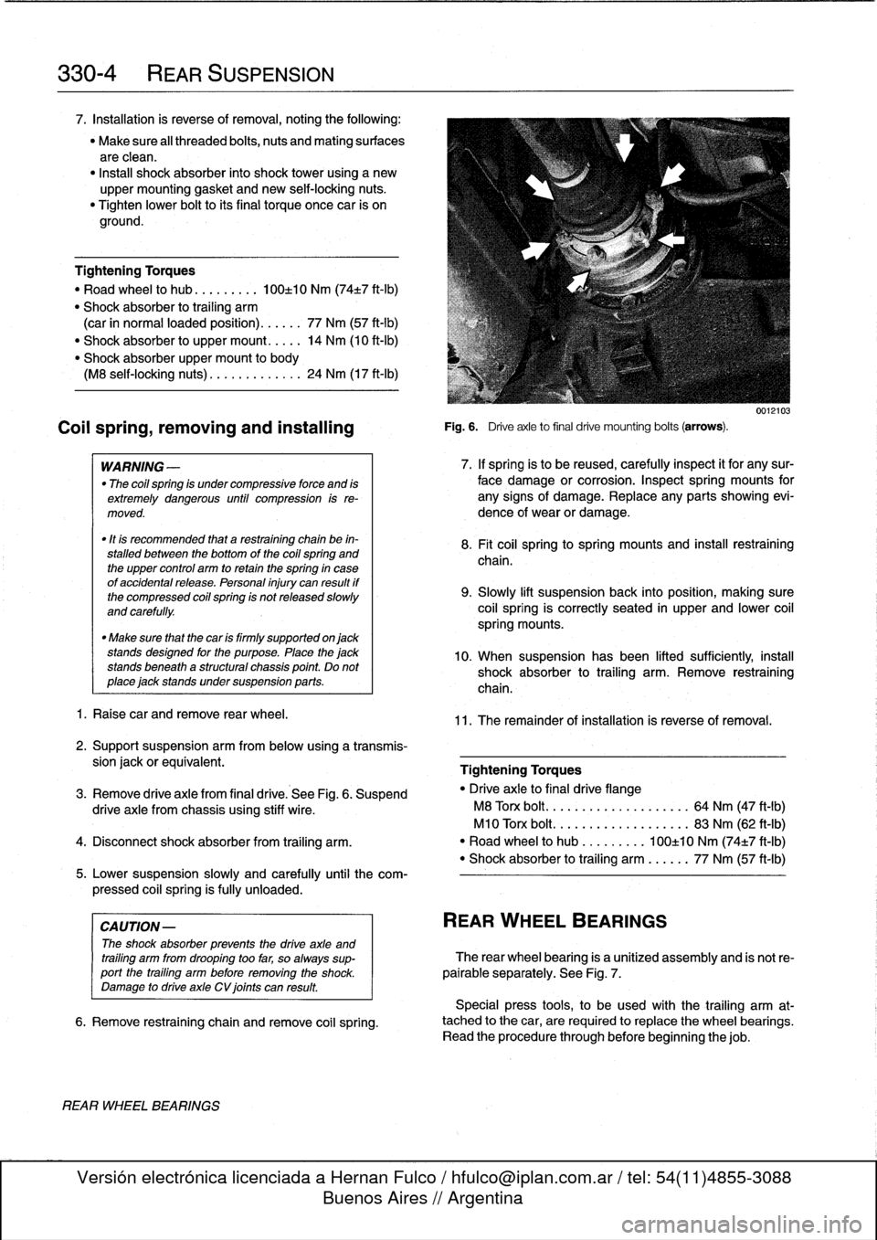
Fig
.
6
.
Driveaxle
to
final
drive
mounting
bolts
(arrows)
.
0012103
7
.
If
spring
is
to
be
reused,
carefully
inspect
it
for
any
sur-
face
damage
or
corrosion
.
Inspect
spring
mounts
for
any
signs
of
damage
.
Replace
any
parts
showing
evi-
dence
of
wear
or
damage
.
8
.
Fit
coil
springtospring
mountsand
insta¡¡
restraíning
chaina
9
.
Slowly
lift
suspensionback
into
position,
making
sure
coil
spring
is
correctly
seated
in
upper
and
lower
coil
spring
mounts
.
10
.
When
suspension
has
been
lifted
sufficiently,
instan
shock
absorber
to
trailing
arm
.
Remove
restraining
chain
.
11
.
The
remainder
of
installation
is
reverse
of
removal
.
REAR
WHEEL
BEARINGS
The
rear
wheel
bearing
is
a
unitized
assembly
and
is
not
re-
pairable
separately
.
See
Fig
.
7
.
Special
press
tools,
to
be
used
with
the
trailing
arm
at-
tached
to
the
car,
are
requiredto
replace
the
wheel
bearings
.
Read
the
procedure
through
before
beginning
thejob
.
Page 278 of 759
330-
6
REAR
SUSPENSION
12
.
Install
brake
caliper
assembly
and
rotor
as
described
in
340Brakes
.
13
.
Install
drive
axie
as
described
below
.
Tightening
Torques
"
Brake
rotor
to
drive
flange
.........
16
Nm
(12
ft-ib)
"
Brake
caliper
to
trailing
arm
........
67
Nm
(50
ft-Ib)
"
Drive
axie
collar
nut
to
drive
flange
..
.
..
..............
250
Nm
(184
ft-Ib)
M3
.....
...
..
.
.............
.
300
Nm
(221
ft-Ib)
"
Road
wheel
to
hub
.........
100±10
Nm
(74±7
ft-Ib)
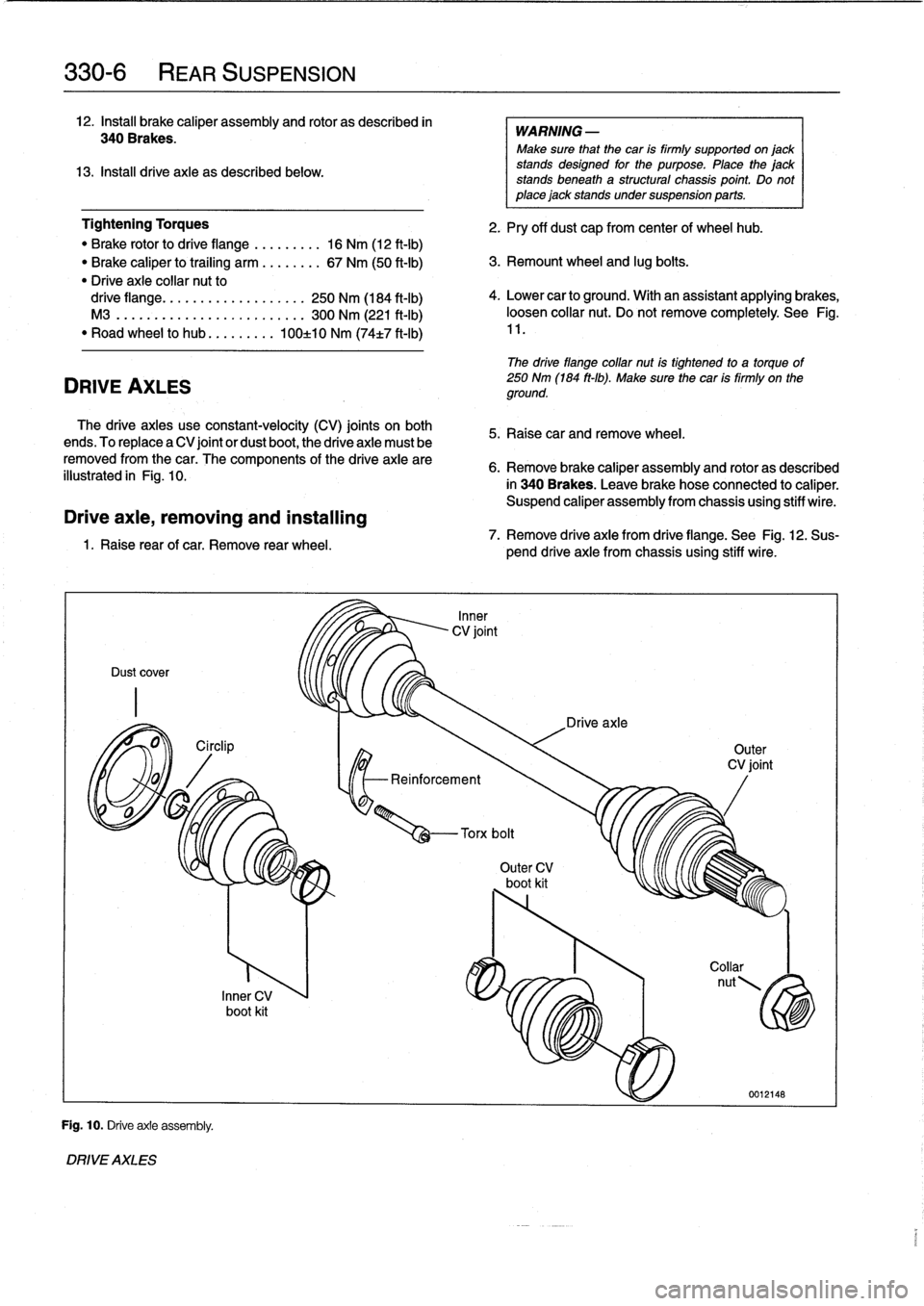
DRIVE
AXLES
The
drive
axles
use
constant-velocity
(CV)
joints
on
both
ends
.
To
replace
a
CV
joint
or
dust
boot,
the
drive
axie
must
be
removed
fromthe
car
.
The
components
of
the
drive
axie
are
illustrated
in
Fig
.
10
.
Drive
axie,
removing
and
installing
1
.
Raise
rear
of
car
.
Remove
rear
wheel
.
Dust
cover
Fig
.
10
.
Driveaxie
assembly
.
DRIVE
AXLES
Inner
CV
boot
kit
-Reinforcement
WARNING
-
Make
sure
that
the
car
is
firmly
supportedon
jack
stands
designed
for
the
purpose
.
Place
the
jack
stands
beneatha
structural
chassis
point
.
Do
not
place
jack
stands
undersuspension
parts
.
2
.
Pry
off
dust
cap
from
center
of
wheel
hub
.
3
.
Remount
wheel
and
lug
boits
.
4
.
Lower
car
to
ground
.
With
an
assistant
applying
brakes,
loosen
collar
nut
.
Do
not
remove
completely
.
See
Fig
.
11
.
The
drive
flange
collar
nut
is
tightened
to
a
torque
of
250
Nm
(184
ft-Ib)
.
Make
sure
the
car
is
firmly
on
the
ground
.
5
.
Raisecar
andremove
wheel
.
6
.
Remove
brake
caliper
assembly
and
rotor
as
described
in
340
Brakes
.
Leave
brake
hose
connected
to
caliper
.
Suspend
caliper
assembly
from
chassis
using
stiff
wire
.
7
.
Remove
drive
axie
from
drive
flange
.
See
Fig
.
12
.
Sus-
pend
drive
axie
from
chassis
using
stiff
wire
.
Outer
CV
boot
kit
Drive
axle
Outer
CV
joint
Page 282 of 759
330-
1
0
REAR
SUSPENSION
Trailing
arm,
removing
and
installing
1
.
Raise
rear
end
of
car
and
remove
wheel
.
WARNING
-
Make
sure
that
the
car
is
firmly
supported
on
jack
standsdesigned
for
the
purpose
.
Place
the
jack
standsbeneatha
structural
chassis
point
.
Do
not
place
jack
stands
under
suspension
parts
.
2
.
Remove
drive
axle
as
described
earlier
.
3
.
Remove
brake
rotor
and
caliper
as
described
in
340
Brakes
.
Do
not
remove
brake
line
from
caliper
.
Hang
caliper
from
body
with
wire
.
4
.
Remove
parking
brakecable
frombrake
shoe
expand-
er
.
See
340
Brakes
.
5
.
Remove
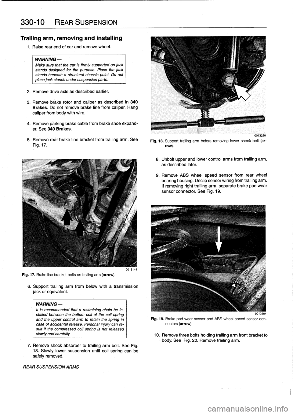
rear
brake
line
bracket
from
trailing
arm
.
See
Fig
.
17
.
Fig
.
17
.
Brake
line
bracket
bolts
on
trailing
arm
(arrow)
.
WARNING
-
It
is
recommended
that
a
restraining
chain
be
in-
stalled
between
the
bottom
coil
of
the
coil
spring
and
the
upper
control
arm
to
retainthe
spring
in
case
of
accidentalrelease
.
Personal
injury
can
re-sult
if
the
compressed
coil
spring
is
not
released
slow1y
and
carefully
.
REAR
SUSPENSION
ARMS
6
.
Support
trailing
arm
from
below
with
a
transmission
jackorequivalent
.
7
.
Remove
shock
absorber
to
trailing
arm
bolt
.
See
Fig
.
18
.
Slowly
lower
suspension
until
coil
spring
can
be
safely
removed
.
0013220
Fig
.
18
.
Support
trailing
arm
before
removing
lower
shock
bolt
(ar-
row)
.
8
.
Unbolt
upper
and
lower
control
arms
from
trailing
arm,
as
described
later
.
9
.
Remove
ABS
wheel
speed
sensor
from
rear
wheel
bearing
housing
.
Unclip
sensor
wiríng
from
trailing
arm
.
If
removing
right
trailing
arm,
separate
brake
pad
wear
sensor
connector
.
See
Fig
.
19
.
0012104
Fig
.
19
.
Brake
pad
wear
sensor
and
ABS
wheel
speed
sensor
con-
nectors
(arrow)
.
10
.
Remove
three
bolts
holding
trailing
arm
front
bracket
to
body
.
See
Fig
.
20
.
Remove
trailing
arm
.
Page 284 of 759
330-
1
2
REAR
SUSPENSION
Upper
control
arm,
removing
and
installing
1.
Raise
rear
end
of
car
and
remove
wheel
.
WARNING
-
Make
sure
that
the
car
is
firmly
supportedon
jack
stands
designed
for
the
purpose
.
Place
the
jack
stands
beneatha
structural
chassis
point
.
Do
not
place
jack
stands
under
suspension
parts
.
2
.
Remove
drive
axle
as
described
earlier
.
3
.
Remove
stabilizer
bar
link
fromupper
control
arm
.
4
.
Support
trailing
arm
from
below
with
a
transmission
jackorequivalent
.
WARNING
-
It
is
recommended
that
a
retaining
chain
be
in-
stalled
between
the
bottom
coil
of
the
coil
spring
and
the
upper
control
arm
to
retain
thespring
in
case
of
accidental
release
.
Personal
injury
can
re-
sult
if
the
compressed
coil
spring
ís
not
released
slowly
and
carefully
.
5
.
Remove
lower
shock
absorber
bolt
.
Refer
to
Fig
.
18
.
Slowly
lower
trailing
arm
until
coil
spring
is
fully
re-
leased
.
Remove
restraining
chain
and
remove
spring
.
7
.
Installation
is
reverse
of
removal
.
"
Always
use
new
self-locking
nuts
.
"
Have
car
professionally
aligned
when
job
is
complete
.
"
Insta¡¡
drive
axle
as
described
earlier
.
Tightening
Torques
"
Drive
axleto
final
drive
flange
M8
Torx
bolt
..........
..
.
..
....
64
Nm
(47
ft-Ib)
M10
Torx
bolt
.........
..
..
.
...
100
Nm
(74
ft-Ib)
"
Shock
absorber
to
trailing
arm
..
..
..
77
Nm
(57
ft-Ib)
"
Upper
control
arm
to
final
drive
carrier
(M12
bolt)
...
..
.
77
Nm
(57
ft-Ib)
"
Upper
control
arm
to
trailing
arm
(M12
bolt)
.........
110
Nm
(81
ft-Ib)
Lower
control
arm,
1
.
Raise
rear
end
of
car
and
support
it
securely
on
jack-
stands
.
Remove
rear
wheel
.
2
.
Remove
both
lower
control
arm
mounting
bolts
.
FINAL
DRIVE
CARRIER
3
.
Use
a
soft
hammer
to
tap
control
arm
out
of
its
mount-
ing
points
.
4
.
Installation
is
reverse
of
removal
.
NOTE-
Use
a
new
bolt
and
washer
assembly
at
the
final
drive
carrier
mountíng
point
forthe
control
arm
.
Tightening
Torque
"
Lower
control
arm
to
final
drive
carrier
(M12
bolt)
......
77
Nm
(57
ft-Ib)
"
Lower
control
arm
to
trailing
arm
(M12
bolt)
....
..
.
..
110
Nm
(81
ft-Ib)
FINAL
DRIVE
CARRIER
Final
drive
carrier,
removing
and
installing
1
.
Raise
rear
end
of
car
and
support
it
securely
on
jack
stands
.
Remove
rear
wheels
.
2
.
Remove
driveshaft
.
See
260
Driveshaft
.
3
.
Remove
both
drive
axles
as
described
earlier
.
6
.
Remove
both
upper
control
arm
mounting
bolts
.
Re-
move
control
arm
.
4
.
Disconnect
stabilizer
bar
from
upper
control
arms
.
Re-
move
stabilizer
bar
mounts
.
5
.
Disconnect
speedometer
harness
connector
on
final
drive
(where
applicable)
.
6
.
Remove
rear
section
of
exhaust
system
.
See
180
Ex-
haust
System
.
NOTE-
It
may
be
easier
to
remove
complete
exhaust
asonepiece
.
See
180
Exhaust
System
.
7
.
Remove
upper
and
lower
control
arms
as
described
earlier
.
8
.
Support
final
drive
carrierwith
transmissíon
jack
.
Re-
move
mounting
bolts
and
nuts
at
final
drive
carrier
bushing
mounts
.
See
Fig
.
22
.
9
.
Slowly
lower
final
drive
and
final
drive
carrier,
detaching
removing
and
installing
wire
harness
and
connectors
as
necessary
.
10
.
Finaldrive
may
now
be
unbolted
from
final
drive
carrier
.
Page 287 of 759
GENERAL
......
.
.
.
.
.
.
.
.....
.
.
.
.
.
.
.
.
.
.
331-1
Final
Drive
Oil
Seals
.
.
...
.
.
.
.......
.
.
.
.
.
331-1
Finaldrive
flange
oil
sea¡,
replacing
....
.
.
.
..
331-2
FINAL
DRIVE
SERVICE
.
.....
.
.
.
.
.
.
.
.
.
.
331-1
Finaldrive
inputshaft
oil
seal,
replacing
.
.
.
.
.
331-3
Final
drive
oí¡,
draining
and
filling
.
.
.
.
.
.
.
.
.
.
331-1
Finaldrive
unit,
removíng
and
installing
.
.
.
.
.
.
331-3
GENERAL
This
repa¡r
group
covers
repair
operations
that
do
not
re-
quire
complicated
disassembly
of
the
final
drive
.
Internal
re-
pairs
and
final
drive
disassembly
are
not
covered
in
this
manual
.
FINAL
DRIVE
SERVICE
Al¡
final
drive
work
requires
some
method
of
raising
thecar
and
supporting
it
securely
while
the
work
is
performed
.
Jack
stands
and
a
floor
jack
can
easily
be
used,
but
use
extreme
caution
when
working
beneath
the
car
.
See010
Fundamen-
tais
for
the
Do-It-Yourself
Owner
.
NOTE-
Removal
of
final
drive
carrier
is
covered
in
330
Rear
Suspension
.
Final
drive
oil,
draining
and
filling
1
.
Drive
car
to
warm
final
drive
fluid
.
2
.
Raise
car
and
support
safely
.
WARNING
-
Make
sure
that
thecar
is
firmly
supported
on
jack
standsdesigned
for
the
purpose
.
Place
the
jack
standsbeneatha
structural
chassis
point
.
Do
not
place
jack
stands
under
suspension
parts
.
5
.
Fill
final
drive
with
appropriate
type
and
quantity
of
lu-
bricant
.
Insta¡¡
and
tighten
fill
plug
.
331
Final
Drive
0
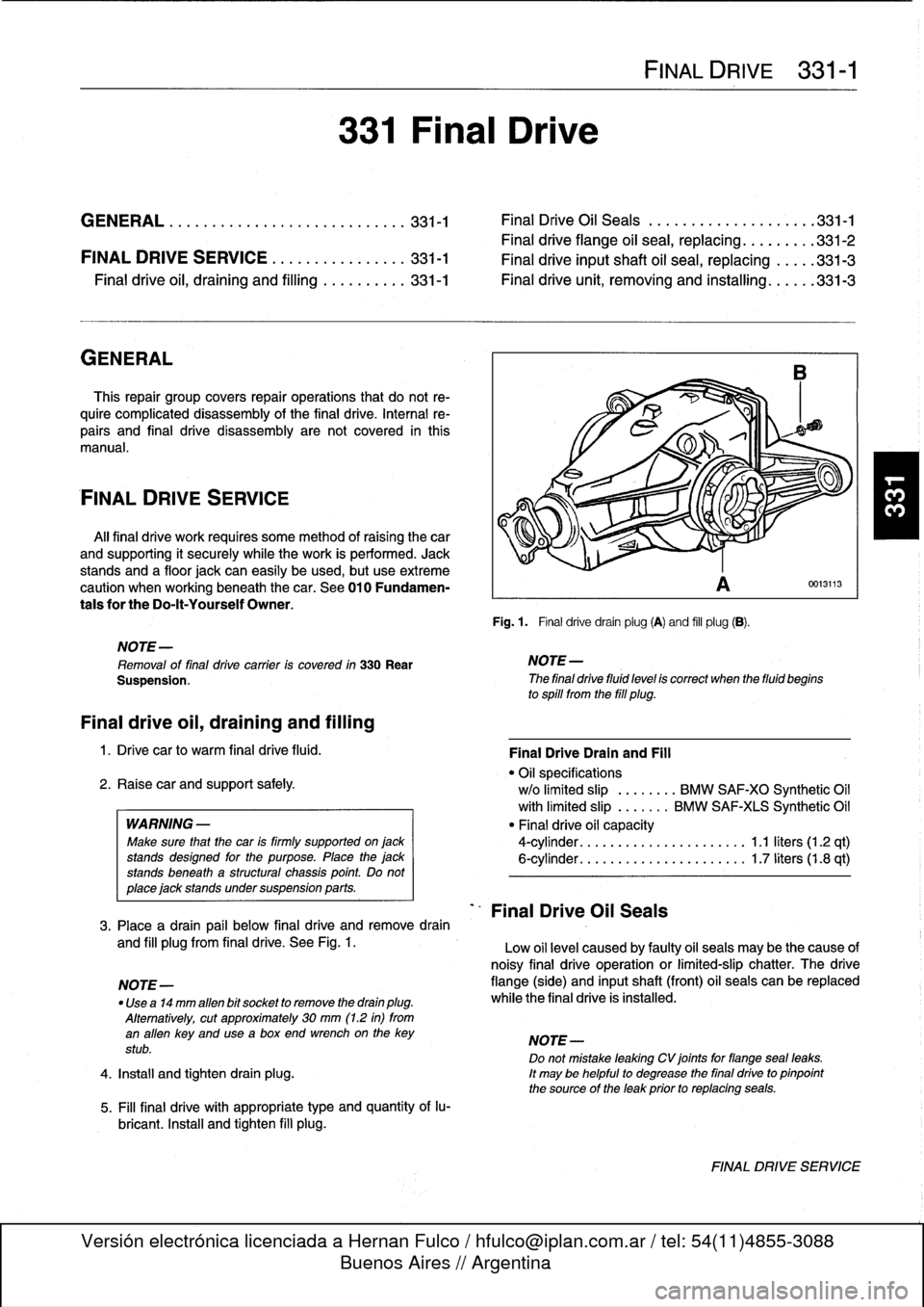
Fig
.
1
.
Final
drivedrain
plug
(A)
and
fill
plug
(B)
.
D
NOTE-
The
final
drive
fluid
level
is
correct
when
the
fluid
begins
to
spill
from
the
fill
plug
.
Final
Drive
Oil
Seals
FINAL
DRIVE
331-1
0013113
Final
DriveDrain
and
Fill
"
Oil
specifications
w/o
limited
slip
.
.......
BMW
SAF-XO
Synthetic
Oil
with
limited
slip
.
......
BMW
SAF-XIS
Synthetic
Oil
"
Final
drive
oil
capacity
4-cylinder
.
.
.
...
................
1
.1
liters
(1
.2
qt)
6-cylinder
.
.
.
...
................
1
.7liters(1.8
qt)
3
.
Place
a
drain
pail
below
final
drive
andremove
drain
and
fill
plugfrom
final
drive
.
See
Fig
.
1
.
Low
oil
level
caused
by
faulty
oil
seals
may
be
the
cause
of
noisy
final
drive
operation
or
limited-slip
chatter
.
The
drive
NOTE-
flange
(side)
and
inputshaft
(front)
oil
seals
can
be
replaced
"
Use
a14
mm
alíen
bit
socket
to
remove
the
drain
plug
.
while
the
final
drive
is
installed
.
Alternatively,
cut
approximately
30
mm
(1
.2
in)
from
an
alíen
key
and
usea
box
end
wrenchon
the
key
NOTE-
stub
.
Do
not
mistake
leaking
CV
joints
for
flangeseal
leaks
.
4
.
Install
and
tighten
drain
plug
.
It
may
be
helpful
to
degrease
the
final
drive
to
pinpoint
the
source
of
the
leak
prior
to
replacing
seals
.
FINAL
DRIVE
SERVICE
Page 289 of 759
Final
driveinputshaft
oil
sea¡,
replacing
1
.
Raise
car
and
support
safely
.
2
.
Drain
final
drive
oil
as
described
earlier
.
3
.
Remove
driveshaft
from
final
drive
inputshaft
flange
.
See
260
Driveshaft
.
4
.
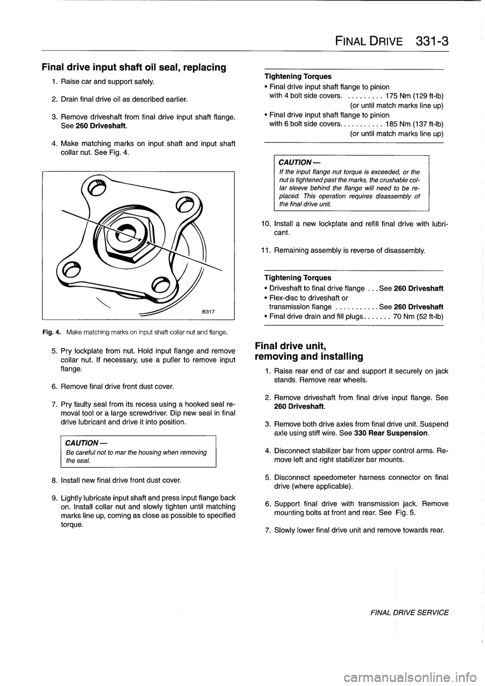
Make
matching
marks
on
input
shaft
and
inputshaft
collar
nut
.
See
Fig
.
4
.
Fig
.
4
.
Make
matching
marks
on
input
shaft
collar
nut
and
flange
.
5
.
Pry
lockplate
from
nut
.
Hold
input
flange
andremove
collar
nut
.
If
necessary,
usea
pullerto
remove
input
flange
.
6
.
Remove
final
drive
front
dust
cover
.
8
.
Install
new
final
drivefront
dust
cover
.
9
.
Lightly
lubricate
inputshaft
and
press
input
flange
back
on
.
Insta¡¡
collar
nut
and
slowly
tighten
until
matching
marks
line
up,
coming
as
close
aspossible
to
specified
torque
.
Tightening
Torques
"
Final
driveinputshaft
flange
to
pinion
with
4
bolt
side
covers
.
.........
175
Nm
(129
ft-Ib)
(or
until
match
marks
line
up)
"
Finaldriveinputshaft
flange
to
pinion
with
6
bolt
side
covers
...........
185
Nm
(137
ft-Ib)
(or
until
match
marks
line
up)
CA
UTION-
If
the
input
flange
nuttorque
is
exceeded,
or
the
nut
is
tightened
past
the
marks,
the
crushable
col-
lar
sleeve
behind
theflange
will
need
to
be
re-
placed
.
This
operation
requires
disassembly
of
the
final
drive
unit
.
10
.
Install
a
new
lockplate
and
refill
final
drive
with
lubri-
cant
.
11
.
Remaining
assembly
is
reverse
of
disassembly
.
Tightening
Torques
"
Driveshaftto
final
dríve
flange
...
See260
Driveshaft
"
Flex-disc
to
driveshaft
or
transmission
flange
...........
See260
Driveshaft
"
Finaldrivedrain
and
fill
plugs
...
.
..
.
70
Nm
(52
ft-Ib)
Final
drive
unit,
removing
and
installing
FINAL
DRIVE
331-
3
1
.
Raise
rear
end
of
car
and
support
it
securely
on
jack
stands
.
Remove
rear
wheels
.
2
.
Remove
driveshaft
from
final
drive
input
flange
.
See
7
.
Pry
faulty
sea¡
from
its
recess
using
a
hooked
sea¡
re-
260
Driveshaft
.
moval
toolor
a
large
screwdriver
.
Dip
new
sea¡
in
final
drive
lubricant
and
drive
it
into
position
.
3
.
Remove
both
drive
axles
from
final
drive
unit
.
Suspend
axle
using
stiff
wire
.
See
330
Rear
Suspension
.
CAUTION
-
ee
careful
not
to
mar
the
housing
when
removing
4
.
Disconnect
stabilizer
bar
from
upper
control
arms
.
Re-
the
seas
.
move
left
and
rightstabilizer
bar
mounts
.
5
.
Disconnect
speedometer
harness
connector
on
final
drive
(where
applicable)
.
6
.
Support
final
drive
with
transmission
jack
.
Remove
mounting
bolts
atfront
and
rear
.
See
Fig
.
5
.
7
.
Slowly
lower
final
drive
unit
and
remove
towards
rear
.
FINAL
DRIVE
SERVICE
Page 293 of 759
When
bleeding
the
brakes,
startat
the
wheel
farthest
from
4
.
Close
bleeder
screw
and
release
brake
pedal
.
Refill
the
master
cylinder
and
progress
in
the
following
order
:
brake
fluid
reservoir
and
proceed
to
rear
left
wheel
.
"
right
rear
brake
5
.
Proceed
with
the
remaining
wheels
using
the
order
list-
"
left
rear
brake
ed
earlier
.
"
rightfront
brake
"
left
front
brake
Pressure
bleeding
brakes
(except
carswith
AST)
1
.
Top
off
brake
fluid
in
reservoir
and
connect
pressure
bleeder
to
reservoir
.
Connect
bleeder
hose
and
bottle
to
right
rearcaliper
bleeder
screw
.
Pressurize
system
to
approximately
1
bar
(14
.5
psi)
.
BRAKES
340-
3
Tightening
Torques
"
Bleeder
screws
:
7
mm
screw
..........
..
.
.
.
.
......
5
Nm
(4
ft-Ib)
9
mm
screw
..........
..
.
..
.......
6
Nm
(5
ft-Ib)
BRAKE
PADS,
CALIPERS,
AND
ROTORS
CAUTION-
TheE36
front
brake
caliper
is
shown
in
Fig
.
2
.
The
rear
Do
not
exceed
a
pressure
of
2
bar
(29
psi)
when
brake
caliper
is
shown
in
Fig
.
7
.
pressure
bleeding
the
brake
system
.
Excessive
pressure
will
damage
the
brake
fluid
reservoir
.
Brake
pads
canbe
replaced
without
disconnecting
the
brake
fluid
hose
from
the
caliper
or
having
to
bleed
the
brakes
.
2
.
Have
a
helperhold
brake
pedal
down
.
The
rotors
can
be
replaced
without
disassembling
the
wheel
huband
bearing
.
Always
machine
or
replace
rotors
in
parts
.
3
.
Open
bleeder
screw
.
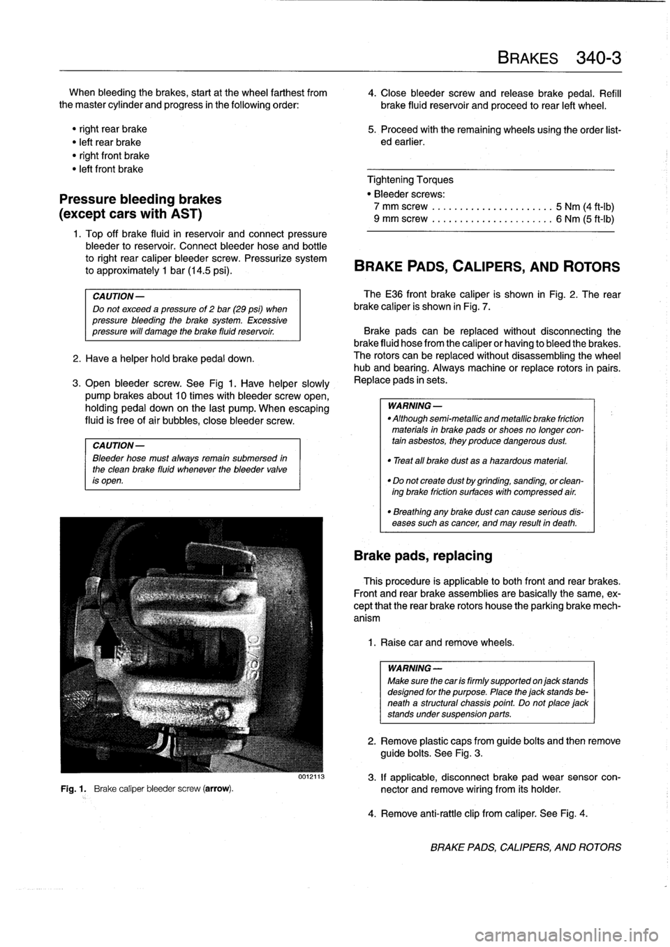
See
Fig
1
.
Have
helper
slowly
,
Replace
pads
in
sets
.
pump
brakes
about10
times
with
bleeder
screw
open,
holding
pedal
down
on
the
last
pump
.
When
escaping
WARNING-
fluid
is
free
of
air
bubbles,
close
bleeder
screw
.
"
Althoughsemi-metallicandmetallicbrake
friction
materials
in
brake
pads
or
shoes
no
longer
con
CAUTION-
tain
asbestos,
they
produce
dangerous
dust
.
Bleeder
hose
must
alwaysremain
submersed
in
"
Treat
all
brake
dust
asa
hazardous
material
.
the
clean
brake
fluid
whenever
the
bleeder
valve
is
open
.
"
Do
not
create
dust
by
grinding,
sanding,
orclean-
ing
brake
friction
surfaces
with
compressed
air
.
"
Breathing
any
brake
dust
can
cause
serious
dis-
eases
such
as
cancer,
and
may
result
in
death
.
Brake
pads,
replacing
This
procedure
is
applicable
lo
both
front
and
rear
brakes
.
Front
and
rear
brake
assemblies
are
basically
the
same,
ex-
cept
that
the
rear
brake
rotors
house
the
parking
brake
mech-
anism
1
.
Raise
car
andremove
wheels
.
WARNING
-
Make
sure
thecar
is
firmly
supported
onjack
stands
designed
for
the
purpose
.
Place
the
jack
stands
be-
neath
a
structural
chassis
point
.
Do
not
place
jack
stands
undersuspension
parts
.
2
.
Remove
plastic
caps
from
guide
bolts
and
then
remove
guide
bolts
.
See
Fig
.
3
.
0012113
3
.
If
applicable,
disconnect
brake
pad
wear
sensor
con-
Fig
.
1
.
Brake
caliper
bleeder
screw
(arrow)
.
nector
and
remove
wiring
from
its
holder
.
4
.
Remove
anti-rattle
clip
from
caliper
.
See
Fig
.
4
.
BRAKE
PADS,
CALIPERS,
AND
ROTORS