wheel BMW 328i 1995 E36 Owner's Manual
[x] Cancel search | Manufacturer: BMW, Model Year: 1995, Model line: 328i, Model: BMW 328i 1995 E36Pages: 759
Page 95 of 759
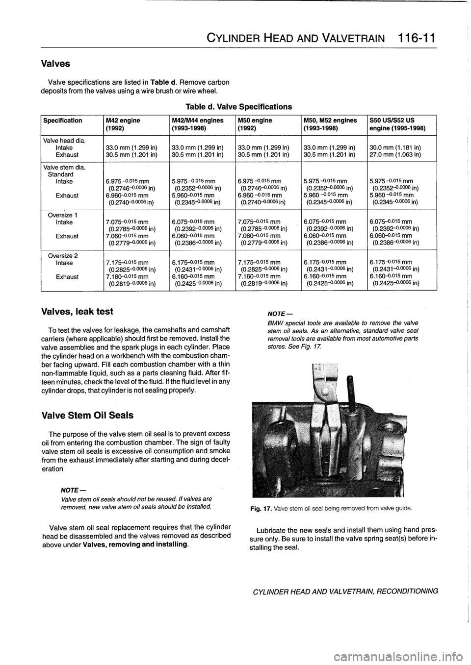
Valves
Valve
specifications
are
listed
in
Table
d
.
Remove
carbon
deposits
from
thevalves
using
a
wire
brush
or
wire
wheel
.
Specification
M42
engine
M42IM44
engines
M50
engine
M50,
M52
engines
S50
USIS52
US
(1992)
(1993-1998)
(1992)
(1993-1998)
I
engine
(1995-1998)
Valve
head
dia
.
Intake
133
.0
mm
(1
.299
in)
133
.0
mm
(1
.299
in)
33
.0
mm
(1
.299
in)
33
.0
mm
(1
.299
in)
130
.0
mm
(1
.181
in)
Exhaust
30
.5
mm
(1
.201
in)
30
.5
mm
(1
.201
in)
30
.5
mm
(1
.201
in)
~
30
.5
mm
(1
.201
in)
27
.0
mm
(1
.063
in)
Valve
stem
dia
.
Standard
Intake
6
.975-0
.015
mm
5
.975-0
.015
mm
6
.975-0
.015
mm
5
.975-0
.015
mm
5
.975-0015
mm
(0
.2746-00006
in)
(0
.2352-00006
in)
(0
.2746-00006
in)
(0
.2352-00006
in)
(0
.2352
-
00006
in)
Exhaust
6
.960-0015
mm
5
.960-0
.015
mm
6
.960
--0
.015
mm
5
.960
-0
.015
mm
5
.960-0
.015
mm
(0
.2740-00006
in)
(0
.2345-0
.0006
in)
(0
.2740--0
.0006
in)
(0
.2345-0
.0006
in)
(0
.2345-0
.0006
in)
Intake
7
.075-0
.015
mm
6
.075-0
.015
mm
7
.075-0
.015
mm
6
.075-0
.015
mm
6
.075-0
.015
mm
(0
.2785-00006
in)
(0
.2392-0
.0006
in)
(0
.2785-00006
in)
(0
.2392
-
00006
in)
(0
.2392-00006
in)
Exhaust
7
.060-0015
mm
6
.060-0015
mm
7
.060-0
.015
mm
6
.060-0015
mm
6
.060-0015
mm
(0
.
2779-0
.0006
in)
(0
.2386-00006
in)
(0
.2779-00006
in)
(0
.2386-00006
in)
(0
.2386-00006
in)
Oversize
2
Intake
7
.175-0
.015
mm
6
.175-0
.015
mm
7
.175-0
.015
mm
6
.175-0
.015
mm
6
.175-0
.015
mm
(0
.2825-00006
in)
(0
.2431-00006
in)
(0
.2825-00006
in)
(0
.2431--0
.0006
in)
(0
.2431-00006
in)
Exhaust
7
.160-0015
mm
6
.160-0015
mm
7
.160-0
.015
mm
6
.160-0015
mm
6
.160-0-015
mm
(0
.2819
-
00006
i
n
)
(0
.2425-00006
in)
(0
.2819-00006
in)
(0
.2425-00006
in)
(0
.2425-00006
in)
Valves,
leak
test
NOTE-
BMW
speclal
tools
are
available
to
remove
the
valve
To
test
thevalves
for
leakage,
the
camshafts
and
camshaft
stem
oil
seals
.
As
an
alternative,
standard
valvesea¡
carriers
(where
applicable)
should
first
be
removed
.
Instali
the
removal
tools
are
available
from
most
automotive
parts
valve
assemblies
and
the
spark
plugs
in
each
cylinder
.
Place
stores
.
See
Flg
.
17
.
the
cylinder
head
on
a
workbench
with
the
combustion
cham-
ber
facing
upward
.
Fill
each
combustion
chamber
with
a
thin
non-flammable
liquid,
suchas
a
parts
cleaning
fluid
.
After
fif-
teenminutes,
check
the
leve¡
of
the
fluid
.
If
the
fluid
level
in
any
cylinder
drops,
thatcylinder
is
not
sealing
properly
.
Valve
Stem
Oil
Seals
The
purpose
of
the
valve
stem
oil
sea¡
is
to
prevent
excess
oil
from
entering
the
combustion
chamber
.
The
sign
offautty
valve
stem
oil
seals
is
excessive
oil
consumption
and
smoke
from
the
exhaust
immediately
after
starting
and
during
decel-
erat¡on
NOTE-
Valve
stem
oil
seals
should
not
be
reused
.
ff
valves
are
removed,
new
valve
stem
oil
seals
should
be
installed
.
Valve
stem
oil
sea¡
replacement
requires
that
the
cylinder
head
be
disassembled
and
thevalves
removed
as
described
above
under
Valves,
removing
and
installing
.
CYLINDER
HEAD
AND
VALVETRAIN
116-
11
Table
d
.
Valve
Specifications
Fig
.
17
.
Valve
stem
oil
sea¡
being
removed
from
valve
guide
.
Lubricate
the
new
seals
and
insta¡]
them
using
hand
pres-
sure
only
.
Be
sure
to
install
the
valve
spring
seat(s)
before
in-
stalling
the
sea¡
.
CYLINDER
HEAD
AND
VALVETRAIN,
RECONDITIONING
Page 99 of 759
NOTE-
The
vibration
damper
center
bolt
is
very
tight
.
A
heavy
duty
holding
device,
such
as
BMW
special
tool
no
.
112
150,
should
be
used
to
hold
the
vibration
damper
hub
V
stationary
while
the
bolt
is
loosened
.
v
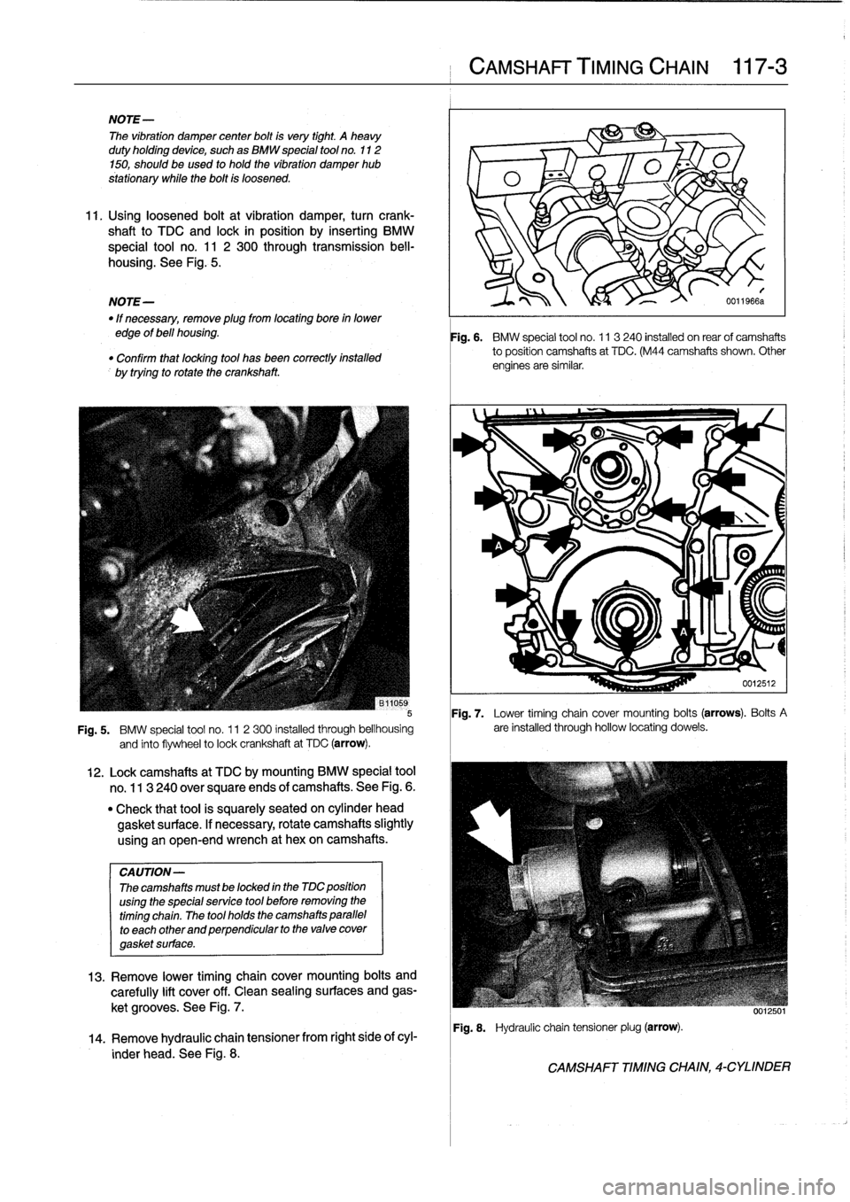
11
.
Usingloosened
bolt
at
vibration
damper,
turn
crank-
shaft
to
TDC
and
lock
in
position
by
inserting
BMW
special
tool
no
.
11
2
300
through
transmission
bell-
-
p
housing
.
See
Fig
.
5
.
v
O
NOTE-
I\
0011966a
"
If
necessary,
remove
plugfrom
locating
boye
in
lower
edge
of
bell
housing
.
"
Confirm
that
locatng
tool
has
been
correctlyinstalled
by
trying
to
rotate
the
crankshaft
.
Fig
.
7
.
Lower
timing
chain
cover
mounting
bolts
(arrows)
.
Bolts
A
Fig
.
5
.
BMW
special
tool
no
.
11
2300
installed
through
bellhousing
are
installed
through
hollow
locating
dowels
.
and
finto
flywheel
to
lock
crankshaft
at
TDC
(arrow)
.
CA
UTION-
Thecamshafts
mustbe
locked
in
the
MC
position
using
the
specialservice
tool
before
removing
the
timing
chain
.
The
tool
holds
the
camshafts
parallel
to
each
other
and
perpendicular
to
the
valve
cover
gasket
surface
.
12
.
Lockcamshafts
at
TDC
bymounting
BMW
special
tool
no
.
113
240
over
square
ends
of
camshafts
.
See
Fig
.
6
.
"
Check
that
tool
is
squarely
seated
on
cylinder
head
gasket
surface
.
If
necessary,
rotate
camshafts
slightly
using
an
open-end
wrench
at
hexon
camshafts
.
13
.
Remove
lower
timing
chaincover
mounting
bolts
and
carefully
lift
cover
off
.
Clean
sealing
surfaces
and
gas-
ket
grooves
.
See
Fig
.
7
.
14
.
Remove
hydraulic
chaintensioner
from
right
side
of
cyl-
inder
head
.
See
Fig
.
8
.
CAMSHAFT
TIMING
CHAIN
117-
3
Fig
.
6
.
BMW
special
tool
no
.
11
3240
installed
on
rearof
camshafts
to
position
camshafts
at
TDC
.
(M44
camshafts
shown
.
Other
engines
are
similar
.
Fig
.
8
.
Hydraulic
chain
tensionerplug
(arrow)
.
CAMSHAFT
TIMING
CHAIN,
4-CYLINDER
Page 104 of 759
117-
8
CAMSHAFT
TIMING
CHAIN
Fig
.
18
.
Oil
baffle'
cover
being
removed
.
Fig
.
19
.
Upper
timing
chaincover
mounting
nuts
(arrows)
on
pre-
VANOS
engines
.
16
.
Secure
crankshaft
hub
to
prevent
crankshaft
from
turn-
ing
.
Using
a
socket,
loosen
but
do
not
remove
crank-
shaft
hub
center
bolt
.
CAMSHAFT
TIMINGCHAINS,
6-CYLINDER
Fig
.
20
.
Engine
set
to
approximate
TDC
.
Camshaft
lobes
face
in
and
arrows
on
sprockets
point
up
(arrows)
.
B1
1123a
Fig
.
21
.
O/
T
(0°TDC)
mark
on
vibration
damper
aligned
with
boss
on
timing
chain
cover
(arrow)
.
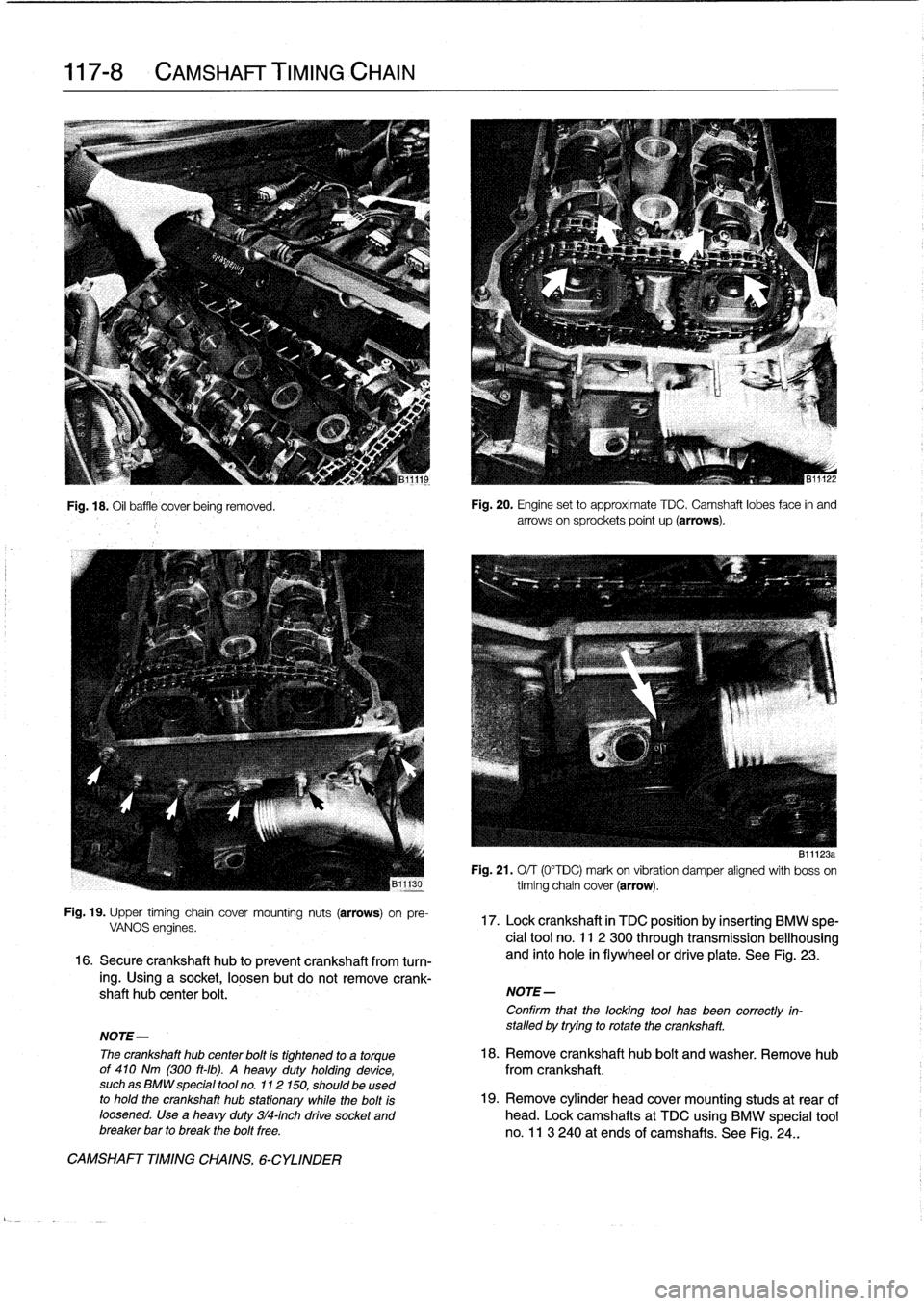
17
.
Lock
crankshaft
in
TDC
position
by
inserting
BMW
spe-
cial
tool
no
.
11
2
300
through
transmissionbellhousing
and
into
hole
in
flywheelor
drive
plate
.
See
Fig
.
23
.
NOTE-
Confirm
that
the
locking
tool
has
been
correctly
in-
stalled
by
trying
to
rotate
the
crankshaft
.
NOTE-
The
crankshaft
hub
center
bolt
is
tightened
to
a
torque
18
.
Remove
crankshaft
hub
bolt
and
washer
.
Remove
hub
of
410
Nm
(300
ft-ib)
.
A
heavy
duty
holding
device,
from
crankshaft
.
suchas
BMW
special
tool
no
.
112150,
should
be
used
to
hold
the
crankshaft
hub
stationary
while
the
bolt
is
19
.
Remove
cylinder
head
cover
mounting
studs
at
rear
of
loosened
.
Use
a
heavy
duty
314-inch
drive
socket
and
head
.
Lock
camshafts
at
TDC
using
BMW
special
tool
breaker
bar
to
break
the
bolt
free
.
no
.
11
3
240
at
ends
of
camshafts
.
See
Fig
.
24
.
.
Page 105 of 759
Fig
.
22
.
Vibration
damper
with
drive
belt
pulley
being
removed
.
Notehub
locating
dowel
(arrow)
.
Fig
.
23
.
BMW
special
tool
no
.
11
2
300
installed
through
bellhousing
and
into
flywheel
.
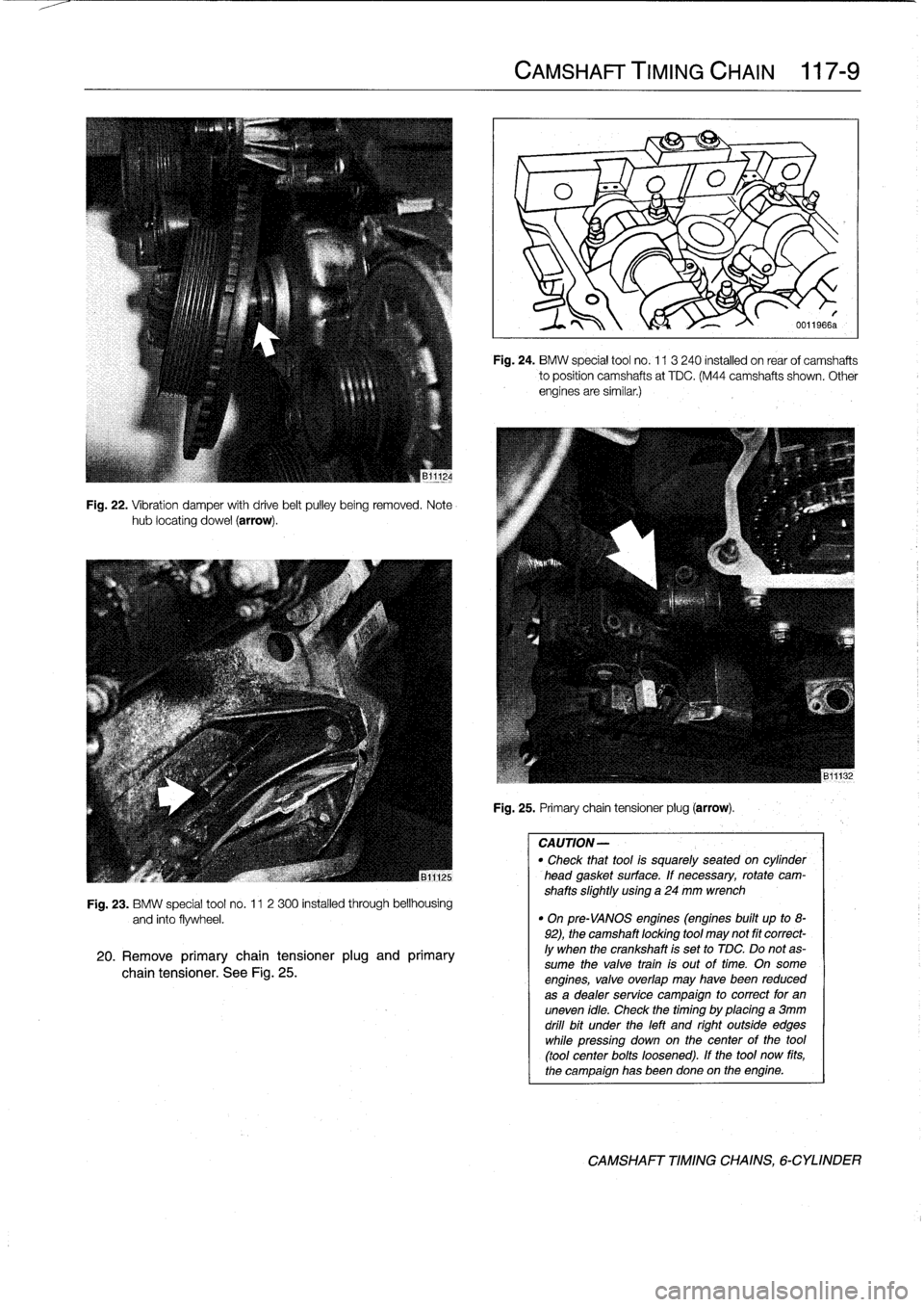
20
.
Remove
primary
chain
tensioner
plug
and
primary
chain
tensioner
.
See
Fig
.
25
.
CAMSHAFT
TIMING
CHAIN
117-
9
Fig
.
24
.
BMW
special
tool
no
.
113
240
installed
on
rear
of
camshafts
to
position
camshafts
at
TDC
.
(M44
camshafts
shown
.
Other
engines
are
similar
.)
Fig
.
25
.
Primary
chain
tensioner
plug
(arrow)
.
CAUTION-
"
Check
thattool
is
squarely
seated
on
cytinder
head
gasket
surface
.
If
necessary,
rotate
cam-
shafts
slightly
using
a
24
mm
wrench
"
On
pre-VANOS
engines
(engines
built
up
to
8-
92),
the
camshaft
locking
tool
may
not
fit
correct-
ly
when
the
crankshaft
is
set
to
TDC
.
Do
notas-
sume
the
valve
train
is
out
oftime
.
On
some
engines,
valve
overlap
may
havebeen
reduced
as
a
dealer
service
campaign
to
correct
for
an
uneven
idle
.
Check
thetiming
by
placing
a
3mm
drill
bit
under
the
left
and
right
outside
edges
while
pressíng
down
on
thecenter
of
the
tool
(tool
center
bolts
loosened)
.
If
the
tool
now
fits,
the
campaign
has
beendone
on
the
engine
.
CAMSHAFT
TIMING
CHAINS,
6-CYLINDER
Page 109 of 759
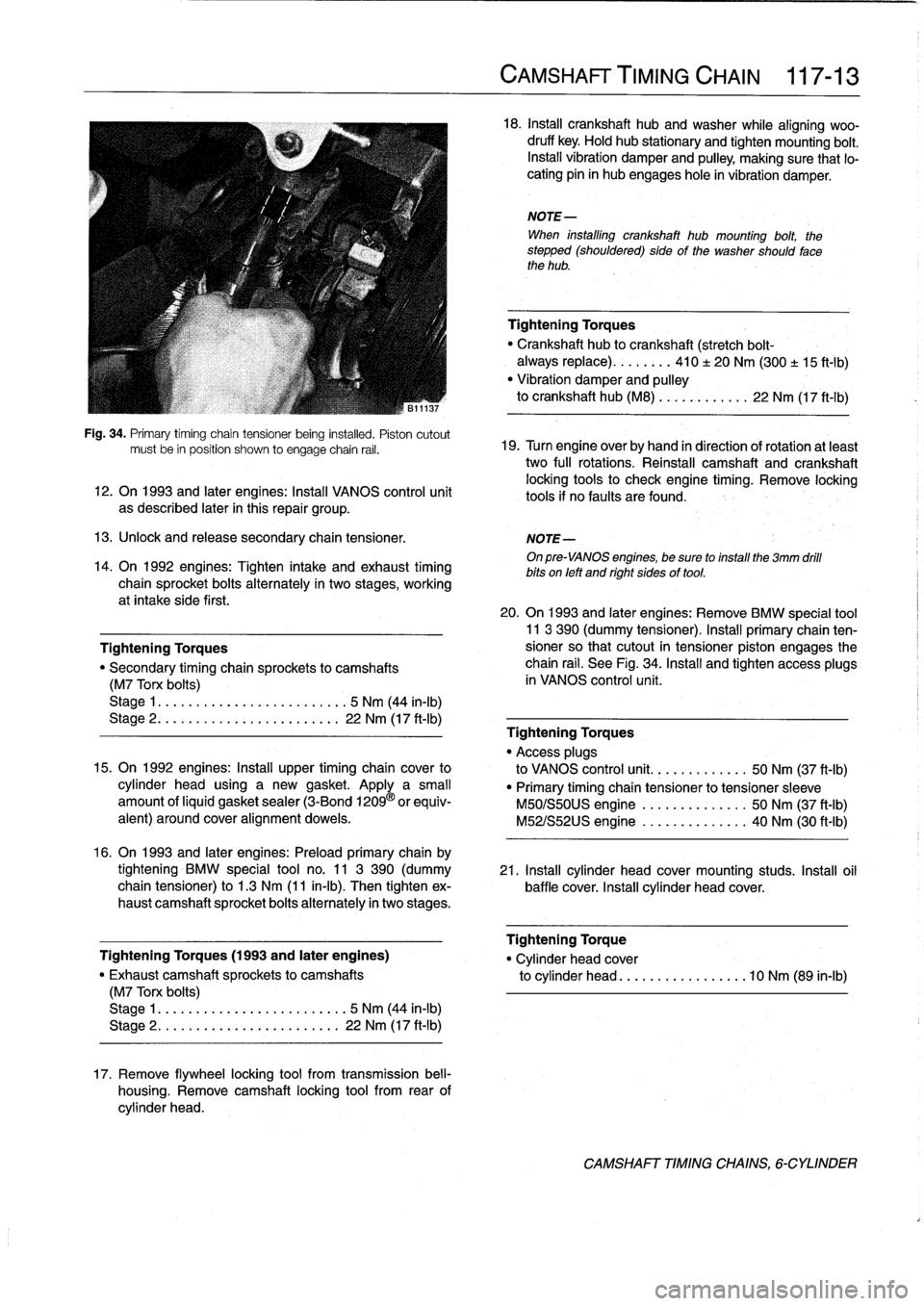
Fig
.
34
.
Primary
timíng
chain
tensioner
being
instafed
.
Pistoncutout
mustbe
in
position
shown
to
engage
chain
rail
.
12
.
On
1993
and
later
engines
:
Install
VANOS
control
unit
as
described
later
in
this
repair
group
.
13
.
Unlock
and
release
secondary
chaintensioner
.
NOTE-
On
pre-VANOS
engines,
be
sure
toinstall
the
3mm
drill
bits
on
left
and
right
sides
of
tool
.
14
.
On
1992
engines
:
Tighten
intake
and
exhaust
timing
chain
sprocket
bolts
alternately
in
two
stages,
working
at
intake
side
first
.
Tightening
Torques
"
Secondary
timing
chaira
sprockets
to
camshafts
(M7
Torx
bolts)
Stage
1
....
.
.
.
...
...............
5
Nm
(44
in-lb)
Stage
2
..
.
.
.
.
.
.
................
22
Nm
(17
ft-Ib)
15
.
On
1992
engines
:
Install
upper
timing
chaincover
to
cylinder
head
using
a
new
gasket
.
Apply
a
small
amount
ofliquid
gasket
sealer
(3-Bond
1209
®
orequiv-
alent)
around
coveralignment
dowels
.
16
.
On
1993
and
later
engines
:
Preloadprimary
chain
by
tightening
BMW
special
tool
no
.
11
3
390
(dummy
21
.
Install
cylinder
head
cover
mounting
studs
.
Insta¡¡
oil
chain
tensioner)
to
1
.3
Nm
(11
in-lb)
.
Then
tighten
ex-
baffle
cover
.
Install
cylinder
head
cover
.
haust
camshaft
sprocket
bolts
alternately
in
twostages
.
Tightening
Torques
(1993
and
later
engines)
"
Exhaust
camshaft
sprockets
to
camshafts
(M7
Torx
bolts)
Stage
1
..
...
..
..
................
5
Nm
(44
in-lb)
Stage
2
.....
.
.
...
..............
22
Nm
(17
ft-Ib)
17
.
Remove
flywheel
locking
tool
from
transmission
bell-
housing
.
Remove
camshaft
locking
tool
from
rear
of
cylinder
head
.
CAMSHAFT'TIMING
CHAIN
117-
1
3
18
.
Insta¡¡
crankshaft
hubandwasher
while
aligning
woo-
druff
key
.
Hold
hub
stationary
and
tighten
mounting
bolt
.
Install
vibration
damper
and
pulley,
making
sure
that
lo-
cating
pin
in
hub
engages
hole
in
vibration
damper
.
NOTE-
When
installing
crankshaft
hub
mounting
bolt,
the
stepped
(shouldered)
sideof
the
washer
should
fase
the
hub
.
Tightening
Torques
Crankshaft
hub
to
crankshaft
(stretch
bolt-
always
replace)
........
410
±
20
Nm
(300
±
15
ft-1b)
"
Vibration
damper
and
pulley
to
crankshaft
hub
(M8)
...
..
.
..
....
22
Nm
(17
ft-Ib)
19
.
Turn
engine
over
by
hand
in
direction
of
rotation
atleast
two
full
rotations
.
Reinstall
camshaft
and
crankshaft
locking
tools
to
check
engine
timing
.
Remove
locking
tools
if
no
faults
are
found
.
20
.
On
1993
and
later
engines
:
Remove
BMW
special
tool11
3
390
(dummy
tensioner)
.
Install
primary
chain
ten-sioner
so
that
cutout
in
tensioner
piston
engages
the
chain
rail
.
See
Fig
.
34
.
Install
and
tighten
access
plugs
in
VANOS
control
unit
.
Tightening
Torques
"
Access
plugs
to
VANOS
control
unit
..........
.
..
50
Nm
(37
ft-Ib)
"
Primary
timing
chain
tensioner
to
tensioner
sleeve
M50/S50US
engine
.......
.
..
..
.
.
50
Nm
(37
ft-Ib)
M52/S52US
engine
..........
..
.
.
40
Nm
(30
ft-Ib)
Tightening
Torque
"
Cylinder
head
cover
to
cylinder
head
............
...
.
.10
Nm
(89
in-lb)
CAMSHAFT
TIMINGCHAINS,
6-CYLINDER
Page 110 of 759
117-
1
4
CAMSHAFT
TIMING
CHAIN
22
.
Installation
of
remaining
parts
is
reverse
of
removal,
When
theengine
is
running,
the
piston
housing
is
supplied
noting
the
following
:
with
pressurized
engine
oil
.
At
idie,
the
solenoid
isin
the
off
"
When
installing
thermostat,
make
sure
arrow
or
vent
position
(de-energized)
and
valve
timing
is
maintained
in
the
hole
faces
up,
if
applicable
.
normal
position
:
When
the
solenoid
is
energized,
the
gear
cup
"
Refill
cooling
systemas
described
in
170
Radiator
piston
moves
forward
to
advance
the
camshaftby
a
maximum
and
Coming
System
.
of
12
.5
.
"
Install
oil
pan
as
described
in
119
Lubrication
Sys-
tem
.
"
Fill
engine
with
oil
and
install
a
new
oil
filter
as
de-
scribed
in
020
Maintenance
Program
.
"
Insta¡¡
ground
wires
at
cylinder
head
cover
mounting
studs
and
at
front
of
cylinder
head
and
thermostat
housing,
where
applicable
.
VANOS
system
operation,
testing
Tightening
Torques
There
are3
special
tools
required
to
check
VANOS
opera-
"
Coolant
drain
plugto
cylinder
block
.
.
25
Nm
(18
ft-Ib)
tion
;
an
electricaltest
lead
(BMW
special
tool
no
.
12
6
410),
an
"
Radiator
cooling
fan
to
coolant
pump
.
40
Nm
(30
ft-Ib)
air
line
fitting
(BMW
special
tool
no
.
11
3
450),
and
a
crank-
"
Radiator
drain
screw
to
radiator
...
.
2
.5
Nm
(22
in-Ib)
shaft
TDC
locking
tool
(BMW
special
tool
no
.
112
300)
.
"
Upper
timing
chaincover
to
cylinder
head
The
test
leal
is
used
to
power
the
solenoid,
simulating
the
M6
nut
...
.....
.............
..
.
10
Nm
(89
in-lb)
ground
signal
from
the
DME
control
unit
.
The
air
line
fitting
M8
bolt
.....
....
.
.
.............
22
Nm
(17
ft-Ib)
takes
the
place
of
the
oil
supply
line
fitting
to
simulate
oil
Ares-
"
VANOS
control
unit
to
cylinder
head
sure
.
The
locking
tool
positions
and
locks
the
crankshaft
at
M6
nut
.........
..
..
.
..........
10
Nm
(89
in-lb)
TDC,
cylinder
no
.
l.
M8
bolt
........
...
.............
22
Nm
(17
ft-Ib)
"
VANOS
oil
supply
pipe
to
VANOS
control
unit
1
.
Remove
alternator
cooling
air
duct
.
banjo
bolt
.......
..
..
.
..........
32
Nm
(24
ft-Ib)
VANOS
(VARIABLE
VALVE
TIMING)
3
.
Remove
top
plastic
enginecovers
.
Disconnect
ignition
coil
harness
connectors
fromcofs
.
Remove
ignition
1993
and
later
6-cylinder
engines
are
equipped
with
a
vari-
coils
.
able
valve
timing
system
called
VANOS
.
This
system
is
con-
trolled
by
the
engine
management
system
and
dynamically
4
.
Remove
cylinder
head
cover
mounting
bolts
and
re-
adjusts
intake
camshaft
timing
based
on
engine
load,
engine
move
cylinder
head
cover
.
Unclip
andremove
oil
baffle
speed
and
engine
temperature
.
cover
from
above
intake
camshaft
.
See
113
Cylinder
Head
Removal
and
installation
.
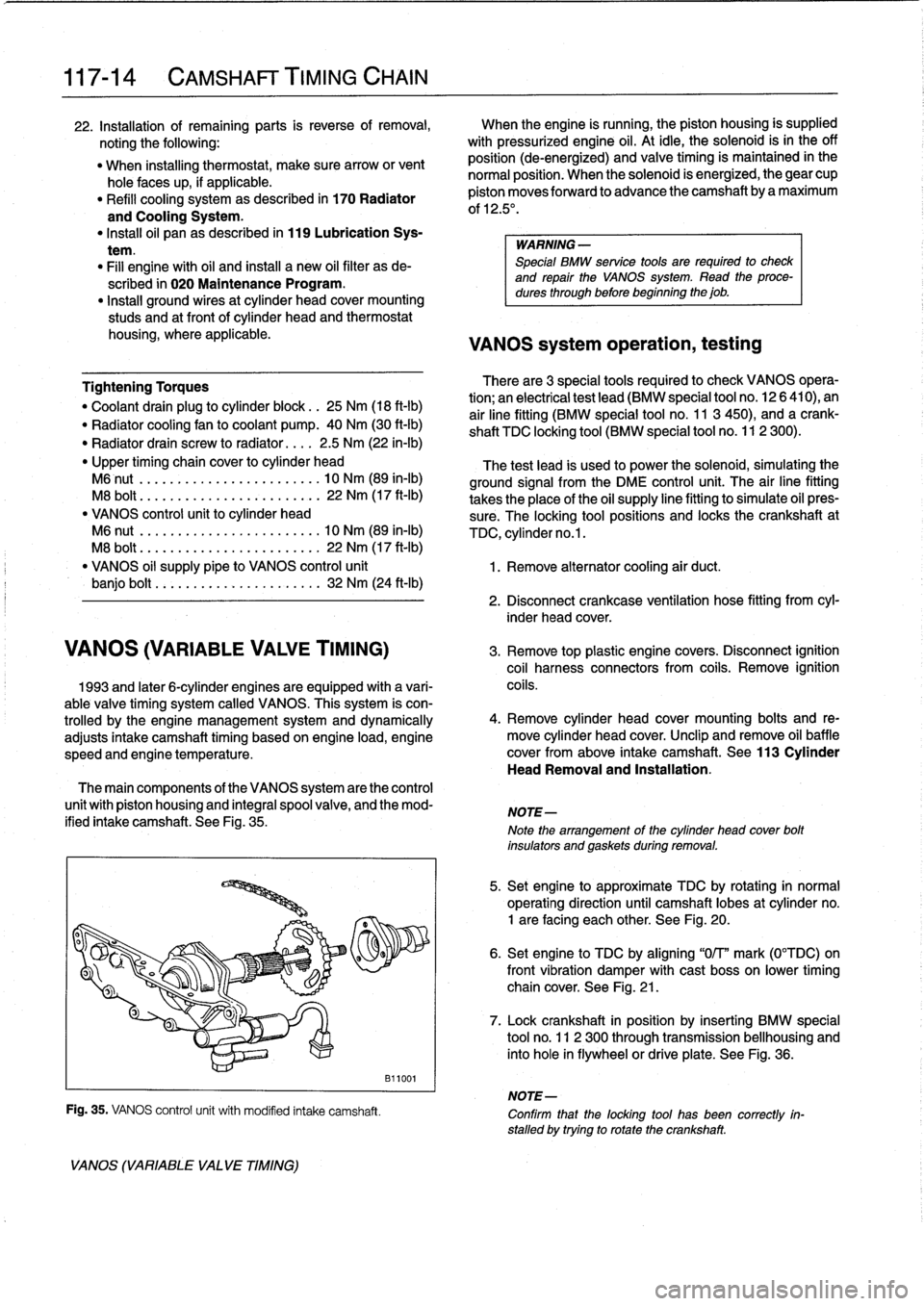
The
main
components
of
the
VANOS
system
are
the
control
unit
with
piston
housing
and
integral
spool
valve,
and
the
mod-
ified
intake
camshaft
.
See
Fig
.
35
.
VANOS
(VARIABLE
VA
LVE
TIMING)
Fig
.
35
.
VANOS
control
unit
with
modified
intake
camshaft
.
B11001
WARNING
-
Special
BMW
service
tools
are
required
to
check
and
repair
the
VANOS
System
.
Read
theproce-
dures
through
before
beginning
the
job
.
2
.
Disconnect
crankcase
ventilation
hose
fitting
from
cyl-
inder
head
cover
.
NOTE-
Note
the
arrangement
of
the
cylinder
head
cover
bolt
insulators
and
gaskets
during
removal
.
5
.
Set
engine
to
approximate
TDC
by
rotating
in
normal
operating
direction
until
camshaft
lobes
at
cylinder
no
.
1
are
facing
each
other
.
See
Fig
.
20
.
6
.
Set
engine
to
TDC
by
aligning
"0/T"
mark
(0°TDC)on
front
vibration
damper
withcast
boss
on
lower
timing
chain
cover
.
See
Fig
.
21
.
7
.
Lock
crankshaft
in
position
by
inserting
BMW
special
tool
no
.
11
2
300
through
transmission
bellhousing
and
into
hole
in
flywheelor
driveplate
.
See
Fig
.
36
.
NOTE-
Confirm
that
the
locking
tool
has
been
correctly
in-
stalled
by
trying
to
rotatethe
crankshaft
.
Page 111 of 759
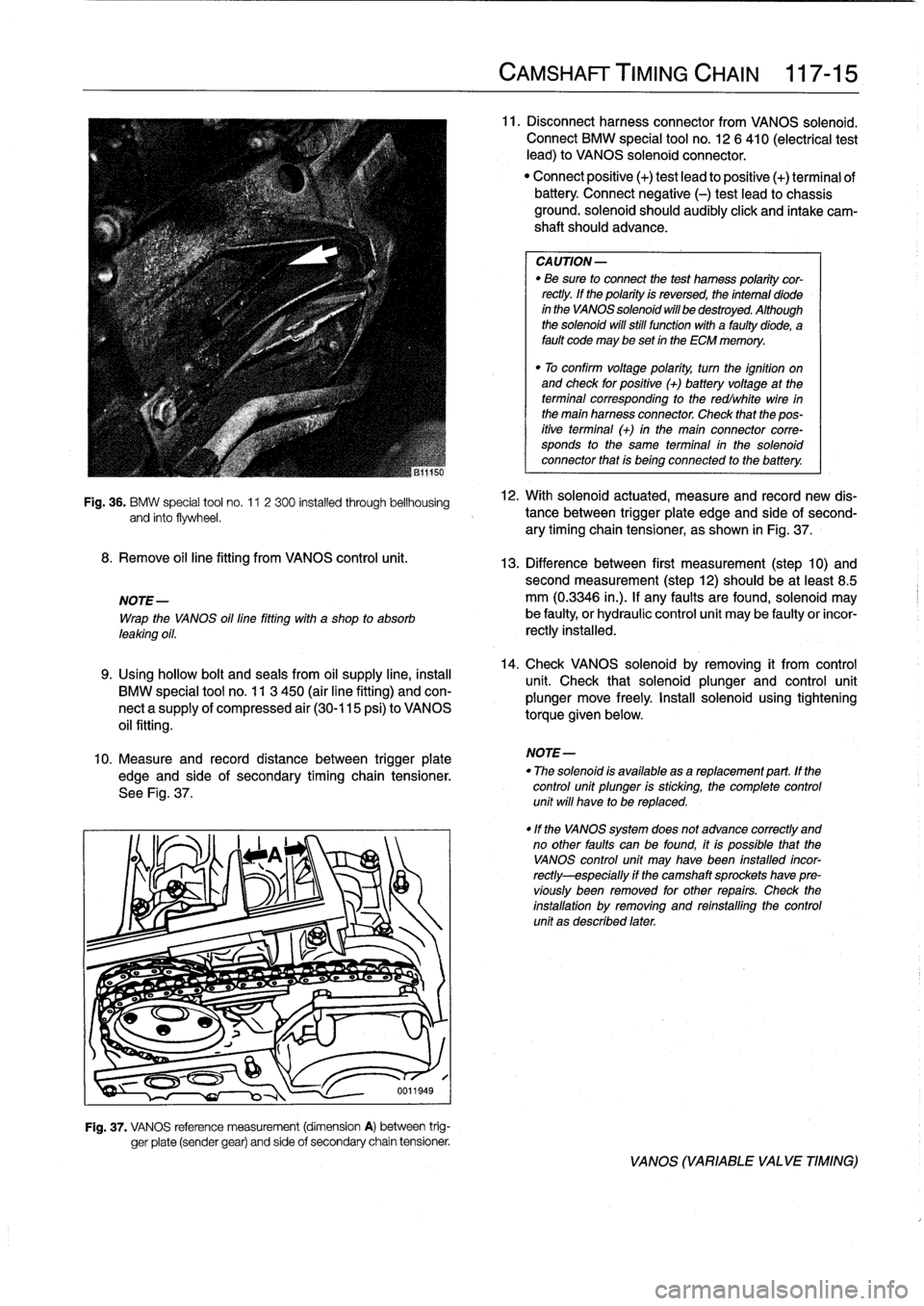
Fig
.
36
.
BMW
special
tool
no
.
11
2
300
installed
through
bellhousing
and
finto
flywheel
.
8
.
Remove
oil
line
fitting
from
VANOS
control
unit
.
NOTE-
Wrap
the
VANOS
oil
line
fitting
with
a
shop
to
absorb
leaking
oil
.
9
.
Using
hollow
bolt
and
seals
from
oil
supply
line,
instan
BMW
special
tool
no
.
11
3
450
(air
line
fitting)
and
con-
nect
a
supply
of
compressed
air
(30-115
psi)
to
VANOS
oil
fitting
.
10
.
Measure
and
record
distance
between
trigger
plate
edge
and
side
of
secondary
timing
chain
tensioner
.
See
Fig
.
37
.
Fig
.
37
.
VANOS
reference
measurement
(dimension
A)
between
trig-
ger
píate
(sender
gear)
and
side
of
secondary
chain
tensioner
.
CAMSHAFT
TIMING
CHAIN
117-
1
5
11
.
Disconnectharness
connector
from
VANOS
solenoid
.
Connect
BMW
special
tool
no
.
12
6
410
(electrical
test
lead)
to
VANOS
solenoid
connector
.
"
Connect
positive
(+)
test
lead
to
positive
(+)
terminal
ofbattery
Connect
negative
(-)
test
leadto
chassis
ground
.
solenoid
should
audibly
click
and
intake
cam-
shaft
should
advance
.
CA
UTION-
"
Be
sure
to
connect
the
test
hamess
polaritycor-
rectly
.
lf
the
polarity
is
reversed,
the
intemal
diode
in
the
VANOS
solenoid
will
be
destroyed
.
Although
the
solenoid
will
still
functionwith
a
faultydiode,
a
fault
code
may
be
set
in
the
ECM
memory
.
"
To
confirm
voltage
polarity,
turn
the
ignition
on
and
check
for
positive
(+)
batteryvoltage
at
the
terminal
corresponding
to
the
redlwhite
wire
in
the
main
harness
connector
.
Check
that
the
pos-
itive
terminal
(+)
in
the
main
connector
corre-
sponds
to
the
same
terminal
in
the
solenoid
connector
that
is
being
connected
to
the
battery
.
12
.
With
solenoid
actuated,
measure
and
record
new
dis-
tance
between
trigger
plate
edge
and
side'of
second-
ary
timing
chain
tensioner,
as
shown
in
Fig
.
37
.
13
.
Difference
between
first
measurement
(step
10)
andsecond
measurement
(step12)
should
be
at
least
8
.5
mm
(0
.3346
in
.)
.
lf
any
faults
arefound,
solenoid
may
be
faulty,
or
hydraulic
control
unit
may
be
faulty
or
incor-
rectly
installed
.
14
.
Check
VANOS
solenoid
byremoving
it
from
control
unit
.
Check
that
solenoid
plunger
and
control
unit
plunger
move
freely
.
Install
solenoid
using
tighteníng
torque
given
below
.
NOTE-
"
The
solenoid
is
available
asareplacement
part
.
lf
the
control
unit
plunger
is
sticking,
the
complete
control
unit
will
have
to
be
replaced
.
"lf
the
VANOS
system
does
not
advance
correctly
and
no
other
faults
can
be
found,
itis
possible
that
the
VANOS
control
unit
may
Nave
been
fnstalled
incor-
rectly-especially
if
the
camshaft
sprockets
have
pre-
víously
been
removed
for
other
repairs
.
Check
the
installation
by
removing
and
reinstalling
the
control
unit
as
described
later
.
VANOS
(VARIABLE
VALVE
TIMING)
Page 112 of 759
117-
1
6
CAMSHAFT
TIMING
CHAIN
15
.
Remove
crankshaft
locking
tool
.
Remove
special
test
equipment
.
Insta¡¡
oil
supply
line
using
new
seals
and
reconnect
solenoid
connector
.
Remainder
of
installa-
tion
is
reverse
of
removal
.
Tightening
Torque
"
Cylinder
head
cover
to
cylinder
head
.
10
Nm
(89
in-lb)
"
VANOS
oil
supply
line
to
VANOS
control
unit
(banjo
bolt)
..
.........
32
Nm
(24
ft-Ib)
"
VANOS
solenoidlo
VANOS
control
unit
........
.
.
.
..
........
30
Nm
(22
ft-Ib)
VANOS
control
unit,
removing
Special
BMW
service
tools
are
required
lo
remove
and
in-
stall
the
VANOS
control
unit
.
Read
the
procedure
through
be-
forestarting
the
job
.
1
.
Remove
radiator
cooling
fan
shroud
and
cooling
fan
.
See
170
Radiator
and
Cooling
System
.
CAUTION-
Radiator
fan
has
left
hand
threads
.
2
.
Remove
top
plastic
engine
covers
.
Disconnect
ignition
coil
harness
connectors
from
coils
.
Remove
ignition
coils
.
Remove
cylinder
head
cover
.
Unclip
andremove
oil
baffle
cover
from
above
intake
camshaft
.See
113
Cylinder
Head
Removal
and
Installation
.
NOTE-
Make
note
of
the
mounting
bolt
insulator
arrangement
during
removal
of
the
cylinder
head
cover
.
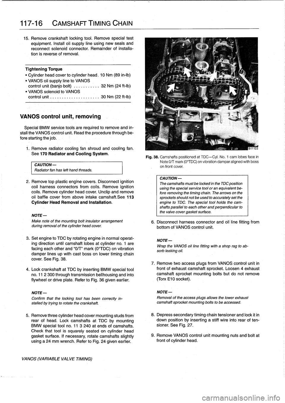
3
.
Set
engine
lo
TDC
by
rotating
engine
in
normal
operat-
ing
direction
until
camshaft
lobes
at
cylinder
no
.
1
are
facing
each
other
and
"0/T"
mark
(0°TDC)
on
vibration
damper
lines
up
with
cast
boss
on
lower
timing
chain
cover
.
See
Fig
.
38
.
4
.
Lock
crankshaft
at
TDC
by
inserting
BMW
special
tool
no
.
11
2
300
through
transmission
bellhousing
and
finto
flywheel
or
drive
plate
.
Refer
to
Fig
.
36
given
earlier
.
NOTE-
Confirm
that
the
locking
tool
has
been
correctly
in-
stalled
by
trying
to
rotatethe
crankshaft
.
5
.
Remove
three
cylinder
head
cover
mounting
studs
from
rear
of
head
.
Lockcamshafts
at
TDC
bymounting
BMW
special
tool
no
.
11
3
240
at
ends
of
camshafts
.
Check
that
tool
is
squarely
seated
on
cylinder
head
gasket
surface
.
If
necessary,
rotate
camshafts
slightly
using
a24
mm
wrench
.
Refer
to
Fig
.
24
given
earlier
.
VANOS
(VARIABLE
VALVE
TIMING)
Fig
.
38
.
Camshafts
positioned
at
TDC-Cyl
.
No
.
1
cam
lobes
face
in
Note
0/T
mark
(0°TDC)
on
vibration
damper
alígned
with
boss
on
front
cover
.
CA
UTION-
Thecamshafts
mustbe
locked
in
the
TDC
position
using
the
specialservice
tool
or
an
equivalent
be-
fore
removing
the
timing
chain
.
Thearrows
on
the
sprockets
should
not
be
used
to
accurately
set
the
engine
to
TDC
The
special
tool
holds
the
cam-
shafts
parallel
to
each
other
and
perpendicular
to
the
valve
cover
gasket
surface
.
6
.
Disconnect
harness
connector
and
oil
line
fitting
from
bottom
of
VANOS
control
unit
.
NOTE-
Wrap
the
VANOS
oilfine
fitting
with
a
shop
rag
to
ab-
sorb
leaking
oil
.
7
.
Remove
two
access
plugs
from
VANOS
control
unit
in
frontof
exhaustcamshaft
sprocket
.
Loosen
4exhaustcamshaft
sprocket
mounting
bolts
but
do
not
remove
(Torx
El
0
socket)
.
NOTE-
Removal
of
the
access
plugs
allows
the
lower
exhaust
camshaft
sprocket
mounting
bolts
to
be
accessed
.
8
.
Depress
secondary
timing
chain
tensioner
and
lock
it
in
down
position
by
inserting
a
stiff
wire
into
rear
of
ten-
sioner
.
See
Fig
.
27
.
9
.
Remove
VANOS
control
unít
mounting
nuts
and
boltat
front
of
cylinder
head
.
Page 114 of 759
117-
1
8
CAMSHAFT
TIMING
CHAIN
CAUTION-
It
is
crítical
that
the
exhaustcamshaft
sprocket
be
turned
only
the
mínimum
amount
necessary
to
engage
the
gear
cup
.
If
this
procedure
is
done
ín-
correctly,
the
VANOS
system
may
not
function
throughout
íts
full
range
.
NOTE-
As
the
control
unit
isinstalled,
the
secondary
sprockets
will
rotate
in
the
counterclockwise
direction
.
It
may
be
necessary
to
guide
sprockets
counterclockwise
as
the
control
unit
is
installed
.
8
.
On
cars
built
from3/95
:
Use
a
spanner
tool
(See
Fig
.
39
.),
turn
exhaust
sprocket
counterclockwise
(as
víewed
from
front
of
engine)
only
enough
to
mesh
gear
cup
splines
with
camshaftgear
.
Slowly
push
VANOS
control
unit
towards
camshaft
until
it
is
fully
seated,guiding
chains
in
counterclockwise
direction
.
CA
UTION-
Ensure
that
the
first
available
tooth
engages
.
9
.
Install
and
tightencontrol
unit
nuts
and
bolt
.
10
.
Connect
harness
connector
to
VANOS
solenoid
.
Using
new
seals,
insta¡¡
oil
line
fitting
.
Tightening
Torques
"
VANOS
control
unitto
cylinder
head
M6
nut
.....
..
..
.
.
.............
10
Nm
(89
in-lb)
M8
bolt
.....
.
.
.
.
..
.............
22
Nm
(17
ft-Ib)
"
VANOS
oil
supply
line
to
control
unit
.
32
Nm
(24
ft-Ib)
11
.
Slowlyunlock
and
release
secondary
chain
tensioner
.
12
.
Preloadprimary
chain
by
tightening
BMW
special
tool
no
.
112
240
(dummy
chain
tensioner)
to
1
.3
Nm
(11
in-
lb)
.
Then
tighten
exhaust
camshaft
sprocket
mounting
bolts
alternately
in
two
stages
.
Tightening
Torque
"
Secondarytiming
chain
sprockets
to
camshafts
(Tora
boits)
Stage
1
..
...............
...
.
.
...
5
Nm
(44
in-lb)
Stage
2
..
...............
...
.
.
..
22
Nm
(17
ft-Ib)
VANOS
(VARIABLE
VALVE
TIMING)
13
.
Remove
flywheel
locking
tool
from
transmission
bell-
housing
.
Remove
camshaft
locking
tool
from
rear
of
cylinder
head
.
14
.
Turn
engine
over
by
hand
at
least
two
fui¡
crankshaft
ro-
tations
.
Reinstall
camshaft
locking
tool
and
flywheel
locking
toolto
make
sure
all
adjustments
are
correct
.
If
settings
are
correct,
remove
locking
tools
.
15
.
Remove
BMW
special
tool
112
420
(dummy
chain
ten-
sioner)
from
side
of
cylinder
head
.
Install
primary
chain
tensioner
so
that
cutout
in
tensioner
piston
engages
chain
rail
.
See
Fig
.
34
.
Using
new
seals,
install
and
tighten
access
plugs
in
VANOS
control
unit
.
Tightening
Torque
"
Access
plugs
to
VANOS
control
unit
.
..
.
.....
.
..
...
50
Nm
(37
ft-lb)
"
Primary
timing
chain
tensioner
plug
to
tensioner
sleeve
M50/S50USengine
.
.
..
.
.
...
.
...
..
50
Nm
(37
ft-Ib)
M52/S52US
engine
...
..
...
...
...
40
Nm
(30
ft-Ib)
16
.
Install
oil
baffle
cover
above
intake
camshaft
.
Install
three
cylinder
head
covermounting
studs
to
rear
of
head
.
Instali
cylinder
head
cover
.
Tightening
Torque
"
Cylinder
head
cover
to
cylinder
head
(M6
screws)
......
10
Nm
(89
in-Ib)
17
.
Installationof
remaining
parts
is
reverse
of
removal
.
NOTE-
Be
sure
to
install
the
ground
wíres
at
the
cylinder
head
cover
mounting
studs
and
at
the
front
of
the
cylinder
head,
if
applicable
.
Page 117 of 759
NOTE
-
The
guide
tube
is
sealed
in
the
pan
with
an
O-ring
.
Check
that
theO-ring
comes
out
with
the
tube
.
Use
a
new
O-ring
when
installing
the
tube
.
Fig
.
2
.
Oil
dipstick
guide
tube
mounting
nut
(arrow)
on
M44
engine
.
Use
new
O-ring
at
base
of
tube
during
installatidn
.
6
.
Install
engine
lifting
equipment
at
front
engine
lifting
point
and
raise
engine
approximately
5
mm
(
1
/4
inch)
until
engineweight
is
supported
.
7
.
Workingbeneath
car,
separate
steering
column
shaft
from
steeringrack
at
universal
joint
.
"
Point
wheels
straight
ahead
before
disconnecting
shaft
from
rack
.
Mark
steering
column
shaft
joint
to
steering
rackspíndle
.
See
320
Steering
and
Wheel
Align-
ment
.
CAUTION
-
In
order
to
avoíd
the
need
for
front-end
realign-
ment,
do
notunbolt
power
steering
rack
from
sus-
pension
crossmember
.
8
.
Supportsuspension
crossmember
(subframe)
from
be-
low
usingappropriate
jacking
equipment
.
9
.
At
left
and
right
sides,
unbolt
control
arm
bushing
carri-
ers
from
body
.
Disconnect
stabilizer
bar
links
fromcon-
trol
arms
.
See
Fig
.
3
.
LUBRICATION
SYSTEM
119-
3
0011960
Fig
.
3
.
Stabilizer
bar
link
nut
(A)
and
control
arm
bushing
carrier
bolts
(B)
.
Right
side
shows
.
10
.
Remove
bolts
from
left
and
right
sides
of
suspension
crossmember
.
RemoveM10
nuts
from
bottom
of
left
and
right
engine
mounts
.
Lower
crossmember
as
far
as
possible
.
See
Fig
.
4
.
uu1ibb4
Fig
.
4
.
Suspension
crossmember
bolts
(A)
and
lower
engine
mount-
ing
nut
(B)
.
Right
side
shows
.
11
.
Remove
clamping
brackets
holding
fuel
lines
to
oil
pan
.
12
.
On
cars
with
automatic
transmission,
remove
ATF
cool-
er
line
brackets
from
oil
pan
.
13
.
Remove
engine
drive
belt
from
power
steering
pump
.
See020
Maintenance
Program
.
14
.
Unbolt
power
steering
pumpbracket
andremove
bracket
with
pump
.
Hang
pump
from
chassis
using
wire
.
OIL
PAN