wheel BMW 328i 1995 E36 Service Manual
[x] Cancel search | Manufacturer: BMW, Model Year: 1995, Model line: 328i, Model: BMW 328i 1995 E36Pages: 759
Page 213 of 759
GENERAL
..
.
......
.
.
.
.....
.
...
.
.
.
.
.
.
.
.
200-1
Manual
Transmission
.
.
.....
.
.
.
.'
.
.
.
.
.
.
.
.
200-1
Automatic
Transmission
.........
.
.
.
.
.
.
.
.
200-1
Transmission
ID
Codes
..........
.
.
.
.
.
.
.
.
200-2
GENERAL
E36
models
areequipped
with
a
longitudinal
drivetrain
.
The
transmission
is
bolted
directly
to
the
rear
of
the
engine
.
A
driveshaft
connects
the
output
shaft
of
thetransmission
to
the
final
drive
.
The
final
drive
is
mounted
lo
the
rear
suspension
and
the
body
.
Individual
drive
axles
with
integrated
constant
velocity
joints
transfer
rotational
power
to
the
rear
wheels
.
Manual
Transmission
Due
to
different
power
characteristics
and
performance
re-
quirements,
four
different
manual
transmissions
are
used
in
the
models
coveredby
this
manual
.
Manual
transmission
ap-
plications
are
given
in
Table
a
.
TRANSMISSION-GENERAL
200-1
200
Transmission-General
TABLES
a
.
Manual
Transmission
Applications
..
...........
200-1
b
.
Automatic
Transmission
Applications
...........
200-1
Fig
.
1
.
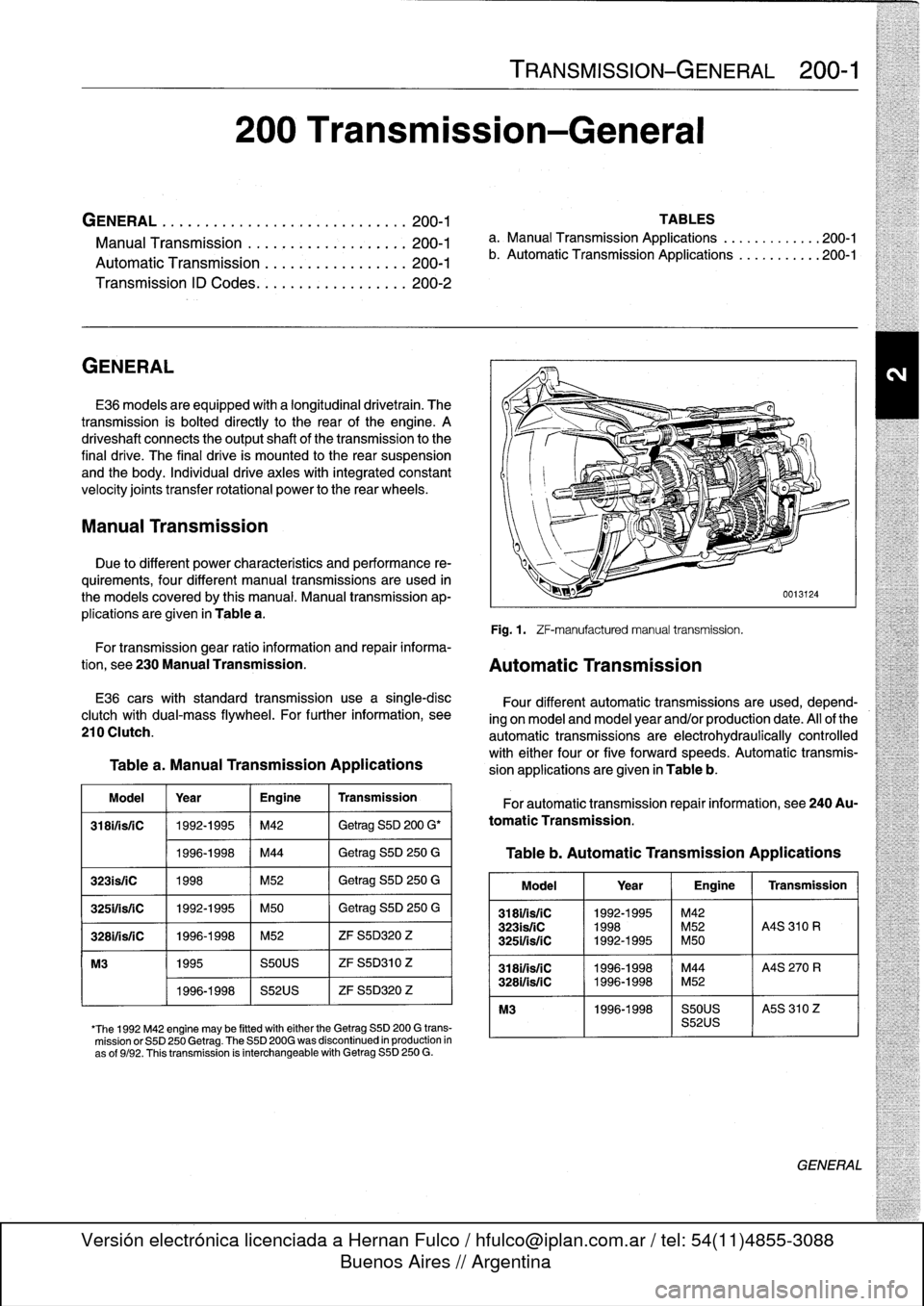
ZF-manufacturedmanual
transmission
.
For
transmission
gear
ratio
information
and
repair
informa-
tion,
see
230
Manual
Transmission
.
Automatic
Transmission
E36
carswith
standard
transmission
use
a
single-disc
clutch
with
dual-mass
flywheel
.
For
further
information,
see
210
Clutch
.
Table
a
.
Manual
Transmission
Applications
Model
Year
Engine
Transmission
318ifisfC
1992-1995
M42
Getrag
S5D
200
G'
1996-1998
M44
Getrag
S5D
250
G
323is/iC
1998
M52
Getrag
S5D
250
G
325ifsriC
1992-1995
M50
Getrag
S5D
250
G
3281/isfC
1996-1998
M52
ZF
S5D320
Z
M3
1995
S50US
ZF
S5D310
Z
1996-1998
S52US
ZF
S5D320
Z
'The
1992
M42
engine
may
be
fitted
witheither
the
Getrag
SSD
200
G
trans-
mission
or
S5D
250
Getrag
.
The
S5D
200G
was
discontinued
in
production
in
as
of
9/92
.
Thistransmission
is
interchangeable
with
Getrag
S5D
250
G
.
Four
different
automatic
transmissions
are
used,
depend-
ing
on
model
and
model
year
and/or
production
date
.
All
of
the
automatic
transmissions
are
electrohydraulically
controlled
with
either
four
or
five
forward
speeds
.
Automatic
transmis-
sion
applications
are
given
in
Table
b
.
For
automatic
transmission
repair
information,
see
240Au-
tomatic
Transmission
.
Table
b
.
Automatic
Transmission
Applications
Model
1
Year
1
Engine
1
Transmission
318i1is/1C
1992-1995
~
M42
323isfiC
1998
M52
A4S
310
R
3251/is/1C
1992-1995
M50
3181/isfC
11996-1998
M44
A4S
270
R
328i/is/1C
1996-1998
M52
M3
1996-1998
S50US
I
A5S
310
Z
S52US
GENERAL
Page 215 of 759
GENERAL
..
.
.
.
.
.
.
.
.
.
.
.
.
.
......
.
......
210-1
CLUTCH
MECHANICAL
.
.
.
.
.
...
.
.....
.
.
210-3
CLUTCH
HYDRAULICS
.
.
.
.............
210-1
Clutch,
removing
.
.
.
.
.
.
.
.
.
.
.
.
.
.
.
.
...
.
.
.
.
210-4
Clutch,inspecting
and
installing
.
.
.
.
.
.
.
.
.
.
.
.210-5Clutch
hydraulic
system,
Transmission
pilot
bearing,replacing
.
.
.
.
...
210-6
bleeding
and
flushing
.
.
.
.
.
.......
.
.....
210-2
Clutch
master
cylinder,
replacing
..
.
.
.
.
.
...
210-2
Table
Clutch
slave
cylinder,
replacing
...
.
.
.
.
.
.
.
.
210-3
a
.
Clutch
Disc
Diameter
.............
..
..
.
......
210-3
GENERAL
CLUTCH
HYDRAULICS
This
repair
group
covers
replacement
of
the
clutch
mechan-
The
Clutch
is
hydraulically
actuated
by
the
master
and
slave
¡cal
and
hydraulic
components
.
Special
tools
may
be
required
cylinders
.
Clutch
disc
wear
is
automatically
taken
upby
the
for
some
of
the
procedures
.
Read
the
procedure
through
be-
pushrod
travelof
the
slave
cylinder,
making
periodic
adjust-fore
beginning
a
job
.
ments
unnecessary
.
NOTE-
See200
Transmission-General
for
transmission
applicatíon
information
.
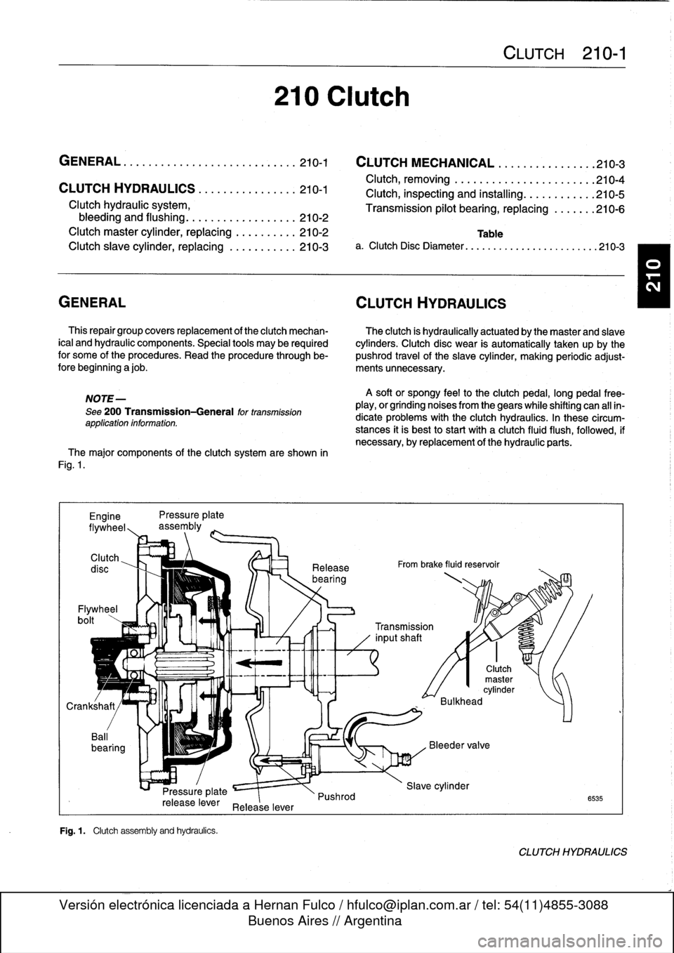
The
major
components
of
the
clutch
system
are
shown
in
Fig
.
1
.
Engine
Pressure
plate
flywheel,,
assembly
Clutch
Flywheel
bolt
Pressure
plate
release
lever
Release
lever
Fig
.
1
.
Clutch
assembly
and
hydraufcs
.
210
Clutch
Release
bearing
Pushrod
A
soft
or
spongy
feel
to
the
clutchpedal,
long
pedal
free-
play,
or
grinding
noises
from
thegears
while
shifting
can
all
in-
dicate
problems
with
the
Clutch
hydraulics
.
In
these
circum-
stances
it
is
best
to
start
with
a
clutch
fluid
flush,
followed,
if
necessary,
byreplacement
of
the
hydraulic
parts
.
From
brake
fluid
reservoir
CLUTCH
210-1
0
0
Transmission
inputshaft
Clutch
master
cylinder
Bulkhead
Slave
cylinder
6535
CLUTCH
HYDRAULICS
Page 218 of 759
210-
4
CLUTCH
Clutch,
removing
1
.
Remove
transmission
fromengine
.
See230
Manual
Transmission
.
2
.
Remove
release
bearing
from
transmission
inputshaft
.
3
.
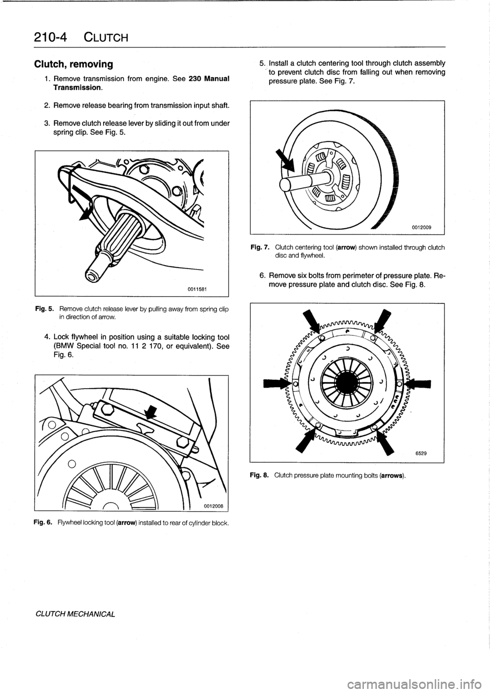
Remove
clutch
release
lever
by
sliding
it
out
from
under
spring
clip
.
See
Fig
.
5
.
Fig
.
5
.
Remove
clutch
release
lever
by
pulling
away
from
spring
clip
in
direction
of
arrow
.
4
.
Lock
flywheel
in
posítion
using
a
suitable
locking
tool
(BMW
Special
tool
no
.
11
2
170,or
equivalent)
.
See
Fig
.
6
.
Fig
.
6
.
Flywheel
locking
tool
(arrow)
installed
to
rear
of
cylinder
block
.
CLUTCH
MECHANICAL
0011581
0012008
5
.
Install
a
clutch
centering
tool
through
clutch
assembly
to
prevent
clutch
disc
from
falling
out
when
removing
pressure
plate
.
See
Fig
.
7
.
Fig
.
7
.
Clutch
centering
tool
(arrow)
shown
installed
through
clutch
disc
and
flywheel
.
6
.
Remove
six
bolts
from
perimeter
of
pressure
plate
.
Re-
move
pressure
plate
and
clutch
disc
.
See
Fig
.
8
.
Fig
.
8
.
Clutch
pressure
plate
mounting
bolts
(arrows)
.
0012009
6529
Page 219 of 759
Clutch,
inspecting
and
installing
1
.
Inspect
clutch
disc
for
wear,
cracks,
loose
rivets,
con-
tamination
or
excessive
runout
(warping)
.
Replace
if
necessary
.
2
.
Inspect
flywheel
for
scoring,
hot
spots,
cracks
or
loose
or
worn
guide
pins
.
Replace
flywheel
if
any
faults
are
found
.
WARNING
-
If
flywheel
is
removed
from
vehicle,
use
new
bolts
duríng
installation
.
The
old
stretch-typebolts
should
not
be
reused
.
3
.
Inspecttransmission
pilot
bearing
in
end
of
crankshaft
.
The
bearing
should
rotate
smoothly
without
play
.
If
nec-
essary,
replace
as
described
later
.
4
.
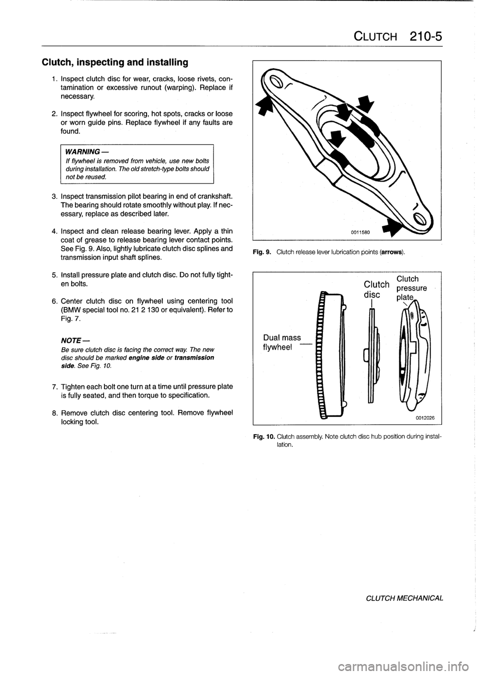
Inspect
and
clean
releasebearing
lever
.
Apply
a
thin
coat
of
grease
to
releasebearíng
lever
contact
points
.
See
Fig
.
9
.
Also,
lightly
lubricate
clutch
disc
splines
and
transmission
inputshaft
splínes
.
5
.
Install
pressure
plate
and
clutch
disc
.
Do
not
fully
tight-
en
bolts
.
6
.
Center
clutch
disc
on
flywheel
using
centering
tool
(BMW
special
tool
no
.
21
2
130
or
equivalent)
.
Refer
to
Fig
.
7
.
NOTE-
Be
sure
clutchdísc
is
facing
the
correct
way
.
The
new
disc
should
bemarked
engine
sfde
or
transmission
side
.
See
Fig
.
10
.
7
.
Tighten
each
bolt
one
turn
at
a
time
until
pressure
plate
is
fully
seated,
and
then
torque
to
specification
.
8
.
Remove
clutch
disc
centering
tool
.
Remove
flywheel
locking
tool
.
Fig
.
9
.
Clutch
release
lever
lubrication
points
(arrows)
.
CLUTCH
210-
5
Clutch
Clutch
pressure
disc
plate
0012026
Fig
.
10
.
Clutch
assembly
Note
clutch
disc
hub
position
during
instal-
lation
.
CLUTCH
MECHANICAL
Page 220 of 759
210-
6
CLUTCH
9
.
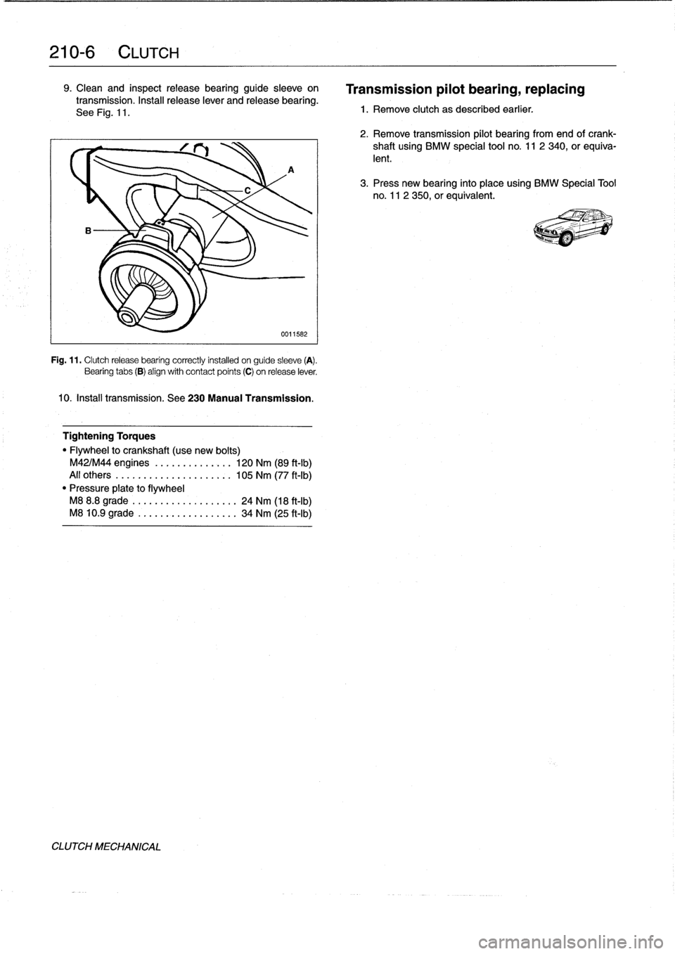
Clean
and
inspectrelease
bearing
guide
sleeve
on
transmission
.
Install
release
lever
and
release
bearing
.
See
Fig
.
11
.
A
0011582
Fig
.
11
.
Clutchrelease
bearing
correctly
installed
on
guide
sleeve
(A)
.
Bearing
tabs
(B)
align
with
contact
points
(C)
on
release
lever
.
10
.
Insta¡¡
transmission
.
See230
Manual
Transmission
.
Tightening
Torques
"
Flywheel
to
crankshaft
(use
new
bolts)
M42/M44
engines
....
.
..
...
....
120
Nm
(89
ft-Ib)
All
others
..........
..
.
..
......
105
Nm
(77
ft-Ib)
"
Pressure
píate
to
flywheel
M8
8
.8
grade
......
...
.
.
........
24
Nm
(18
ft-Ib)
M8
10
.9
grade
.....
..
..
..
.......
34
Nm
(25
ft-Ib)
CLUTCH
MECHANICAL
Transmission
pilot
bearing,
replacing
1
.
Remove
clutch
as
described
earlier
.
2
.
Remove
transmission
pilot
bearing
from
end
ofcrank-
shaft
using
BMW
special
tool
no
.
11
2
340,
or
equiva-
lent
.
3
.
Press
new
bearing
finto
placeusing
BMW
Specíal
Tool
no
.
11
2
350,or
equivalent
.
Page 229 of 759
AUTOMATIC
TRANSMISSION
240-1
240
Automatic
Transmission
GENERAL
.....
.
.
.
.
.
.
.
.
.
.
.
.
.
.........
.
240-1
TRANSMISSION
REMOVAL
AND
INSTALLATION
..................
.
.
.
.
.240-4
TRANSMISSION
SERVICE
.
.
.
.
.
.......
.
240-1
Transmission,
removing
and
installing
....
.
.
.240-4
ATF
leve¡,
checking
..
.
.
.
.
.
.
.
.
.
..........
240-1
ATF,
draining
and
filling
.
.
.
.
.
.
.
..........
240-2
TABLE
a
.
Automatic
Transmission
Gear
Ratios
.......
..
.
.
240-1
GENERAL
TRANSMISSION
SERVICE
lo
Automatic
transmissions
are
identified
by
code
letters
ATF
leve¡,
checking
foundon
a
data
plate
located
on
the
sideof
thetransmission
case,
behind
the
manual
valve
lever
.
See
200Transmis-
The
automatic
transmissions
installed
in
the
E36
models
sion-General
for
application
information
.
Forgear
ratio
spec-
are
normally
filled
with
Dexron
III
automatic
transmission
fluid
ifications,
see
Table
a
.
(ATF),
although
alternative
fluids
have
been
installed
from
the
factory,
depending
on
transmission
type
and
model
year
.
CAUTION-
Some
transmíssions
are
filled
with
a
special
BMW
"lifetime"
ATF
does
not
circulate
unless
the
engine
is
run-
automatic
transmission
fluid,
which
does
not
require
periodic
ning
.
When
towing
an
automafic
transmission
ve-
fluid
changes
.
hicle,
usea
flat-bed
truck
or
ralse
the
rear
wheels
off
the
ground
.
CAUTION-
Mixing
different
types
of
transmission
fluids
will
The
electronic
transmission
control
module
(TCM)
monitors
lead
to
transmission
failure
.
transmissionoperation
for
faults
and
alerts
the
driver
by
illumi-
nating
the
transmission
fault
indicator
on
the
instrument
pan-
el
.
On-board
diagnostic
codes
stored
in
the
TCM
mustbe
NOTE-
downloaded
and
interpreted
by
trained
technicians
using
spe-
The
transmission
lubricant
instafed
can
be
foundona
cial
BMW
diagnostic
equipment
.
type
plate
on
the
side
of
the
transmission
.
In
addition,
a
sticker
may
be
located
on
the
fluid
sump
indicatingthe
typeof
transmission
lubricant
used
.
Ifin
doubt,
con
NOTE-
sult
an
authorized
BMW
dealer
for
altemate
fluid
use
Internal
repairs
to
the
automatic
transmission
require
and
current
information
regardingtransmission
operat-
special
service
equipment
and
knowledge
.
If
it
is
deter-
ing
fluids
.
mined
thatinterna¡
service
is
required,
consult
en
au-
thorízedBMWdealerabouta
factoryreconditioned
unit
The
transmission
is
not
equipped
with
a
dipstick
.
Checking
or
a
transmission
rebuild
.
the
ATF
leve¡
requires
measuring
and
maintaining
a
specified
ATF
temperature
during
the
checking
procedure
.
The
check-
ing
temperature
is
not
fully
warm
orcold
(the
ATF
sump
should
be
approximately
warm
to
the
touch)
.
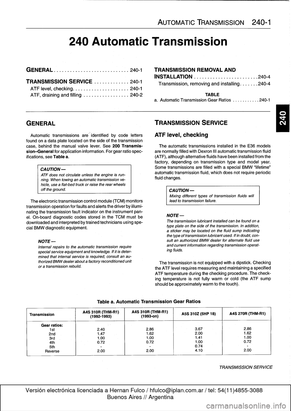
Table
a
.
Automatic
Transmission
Gear
Ratios
Transmission
MS
310R
(THM-R1)
MS
310R
(THM-Rl)
MS
310Z(5HP
18)
I
MS
270R
(THM-R1)
(1992-1993)(1993-on)
Gear
ratios
:
1st
2
.40
2
.86
3
.67
2
.86
2nd
1
.47
1
.62
2
.00
1
.62
3rd
1
.00
1
.00
1.41
1
.00
4th
0
.72
0
.72
1
.00
0
.72
5th
-
-
0
.74
-
Reverse
2
.00
2
.00
4
.10
2
.00
TRANSMISSIONSERVICE
Page 241 of 759
DRIVESHAFT
SERVICE
.
...
.
.
.
...
.
..
.
.
.260-3
Driveshaft,
aligning
...............
.
...
.
.
260-3
Driveshaft,
removing
..............
.
.
.
.
.
.
260-4
260
Driveshaft
DRIVESHAFT
260-1
GENERAL
.
.
.
.
.
.
.
.....
.
.
.
........
.
...
.
260-1
Driveshaft,
installing
.
....
.
..
.
............
260-4
Flex-disc,
replacing
.....
.
.
.
.............
260-5
TROUBLESHOOTING
..
.
.
.
...
.
.........
260-1
Center
bearing
assembly,
replacing
.
......
.260-6
Frontcentering
guide,
replacing
..
.
.......
.
260-7
TABLE
a
.
Driveshaft
Troubleshooting
.
.
...
......
.
....
..
.
.
260-2
GENERAL
NOTE-
For
rear
drive
axlerepair
information,
see330
Rear
The
two-piece
driveshaft
is
joined
in
thecenter
by
a
sliding
Suspension
.
splined
coupling
.
This
coupling
compensates
for
fore
and
aft
movement
of
the
drive
line
.
The
driveshaft
ís
connected
to
the
Driveshaft
noise
or
vibration
may
be
caused
by
worn
or
transmission
bya
rubber
flex-disc
and
to
the
final
drive
by
a
damaged
components
.
Check
the
universal
joints
for
play
.
universal
joint
.
It
is
supported
in
the
micidle
by
a
center
support
With
the
driveshaft
installed,
pull
and
twist
the
driveshaft
while
bearing
.
The
bearing
is
mounted
in
rubber
to
isolate
vibration
.
watching
the
joint
.
The
BMW
specificationfor
play
is
very
See
Fig
.
1
.
small,
so
almost
any
noticeableplay
could
indicate
a
problem
.
TROU
BLESHOOTING
Check
thetorque
of
thefasteners
at
the
flange
connections
.
Check
therubber
of
the
flex-disc
and
center
bearing
for
dete
The
source
of
driveline
vibrations
and
noise
can
be
difficult
rioration
or
tearíng
and
check
for
preload
at
the
center
bearing
to
pinpoint
.
Engine,
transmission,
rear
axle,
or
wheel
vibra-
with
a
visual
inspection
.
Check
the
driveshaft
for
broken
or
tions
can
be
transmitted
through
the
driveshaft
to
the
car
missing
balance
weights
.
The
weights
are
welded
tabs
on
the
body
.
Noises
from
the
rear
of
thecar
may
be
caused
by
final
driveshaft
tubes
.
In
addition
to
inspecting
for
faulty
driveshaft
drive
problems,
orby
faulty
wheel
bearings,
drive
axies,
or
parts,
the
installed
angles
of
the
driveshaft
should
also
be
evenworn
or
improperly
inflatedtires
.
considered
.
Flex-disc
Center
universal
joint
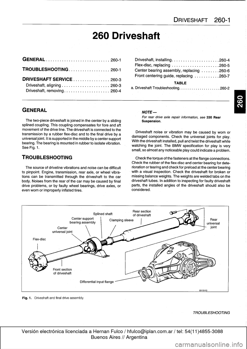
Fig
.1
.
Driveshaft
and
final
drive
assembly
.
Rear
section
Splined
shaft
of
driveshaft
Center
support
`
Clamping
sleeve
bearíng
assembly
Differential
inputflange
0013110
TROUBLESHOOTING
Page 244 of 759
260-
4
DRIVESHAFT
CAUTION
-
The
maximum
allowable
change
in
height
of
the
center
bearing
or
transmission
support
using
shims
is
3
mm
(0
.12
in
.)
.
Driveshaft,
removing
WARNING
-
"
Be
sure
the
wheels
are
off
the
ground
before
re-
moving
the
driveshaft
.
Set
the
parking
brake
be-
fore
removing
the
driveshaft
.
"
Once
the
driveshaft
has
been
removed,
the
vehi-
cle
can
roll
regardless
of
whether
the
transmis-
sion
isin
gear
or
not
.
"
The
driveshaft
fs
mounted
to
thetransmission
and
final
drive
with
self-locking
nuts
.
These
nuts
are
designed
to
be
used
only
once
and
should
be
replaced
during
reassembly
.
1.
Disconnect
oxygen
sensor
electrical
connectors
and
remove
complete
exhaustsystem
.
See
180
Exhaust
System
.
4
.
Remove
driveshaft
mounting
bolts
.
See
Fig
.
3
.
Discard
old
nuts
.
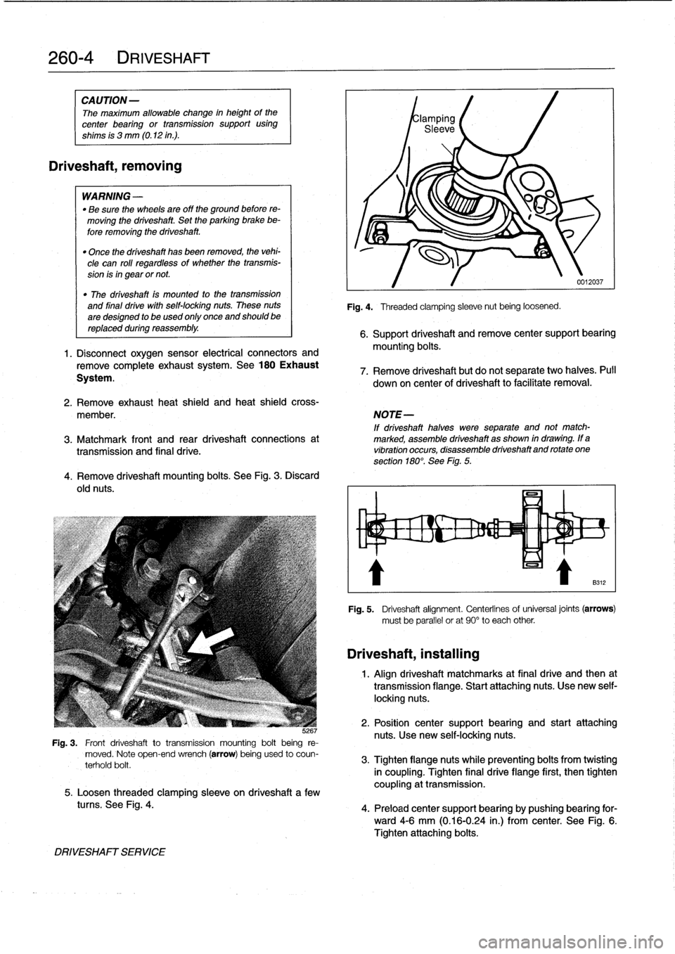
JG
Fig
.
3
.
Front
driveshaft
totransmission
mounting
bolt
being
re-
moved
.
Note
open-end
wrench
(arrow)
being
used
to
coun-
terhold
bolt
.
5
.
Loosen
threaded
clamping
sleeve
on
driveshaft
a
few
tucos
.
See
Fig
.
4
.
DRIVESHAFT
SERVICE
Fig
.
4
.
Threaded
clamping
sleeve
nut
being
loosened
.
0012037
6
.
Support
driveshaft
andremove
center
support
bearing
mounting
bolts
.
7
.
Remove
driveshaft
but
do
not
separate
two
halves
.
Pull
down
on
center
of
driveshaft
to
facilitate
removal
.
2
.
Remove
exhaust
heat
shield
and
heat
shieldcross-
member
.
NOTE-
If
driveshaft
halves
were
separate
and
not
match-
3
.
Matchmark
front
and
rear
driveshaft
connections
at
marked,
assemble
driveshaft
as
shown
in
drawing
.
If
a
transmissíon
and
final
drive
.
vibration
occurs,
disassemble
driveshaftand
rotate
one
section
180°
.
See
Fig
.
5
.
Driveshaft,
installing
Fig
.
5
.
Driveshaft
alignment
.
Centerlinesof
universal
joints
(arrows)
must
be
parallel
or
at
90°
to
each
other
1
.
Align
driveshaft
matchmarks
at
final
drive
and
then
at
transmission
flange
.
Start
attaching
nuts
.
Use
new
self-
locking
nuts
.
2
.
Position
center
support
bearing
and
start
attaching
nuts
.
Use
new
self-locking
nuts
.
3
.
Tighten
flangenuts
while
preventing
bolts
from
twisting
in
coupling
.
Tighten
final
drive
flange
first,
then
tighten
coupling
at
transmission
.
4
.
Preload
center
support
bearing
by
pushing
bearing
for-
ward4-6
mm
(0
.16-0
.24
in
.)
from
center
.
See
Fig
.
6
.
Tighten
attaching
bolts
.
Page 249 of 759
SUSPENSION,
STEERING
ANDBRAKES-GENERAL
300-1
300
Suspension,
Steering
and
Brakes-General
GENERAL
.....
.
....
.
.....
.
.
.
........
.300-1
M3
SUSPENSION
AND
BRAKES
.......
.
...
300-7
Front
Suspension
..........
.
.
.
...
.
.....
300-1
Steering
...
.
.
.
.
.
....
.
.
.
...
.
.
.
...
.
...
.
.
300-2
SUSPENSION
AND
STEERING
Rear
Suspension
....
.
.
.
...
.
.
.
...
.
.....
300-2
TROUBLESHOOTING
..
.
.
.
.............
300-7
Brakes
.
.
.
.
.
.
.
.
....
.
...........
.
.
.
.
.
.
300-2
Tires
and
wheeis
.
................
.
.
.
.
.
.
300-2
TABLE
a
.
AST
Indicator
Lamp
Function
..
..
.
..
.
.........
300-5
INTEGRATED
SYSTEMS
.........
.
.
.
.
.
.
300-2
b
.
Suspension
and
Steering
Troubleshooting
......
.300-8
Antilock
Brake
System
(ABS)
.......
.
.
.
.
.
.
300-2
Al¡
Season
Traction
(AST)
.........
.
.
.
.
.
.
300-4
GENERAL
Front
Suspension
This
section
covers
general
information
for
front
and
rear
The
lower
control
arms
connect
the
front
suspension
struts
suspension,
the
steering
system,
and
the
brakíng
and
traction
to
mounting
points
on
the
subframe
crossmember
and
the
control
systems
.
body
.
See
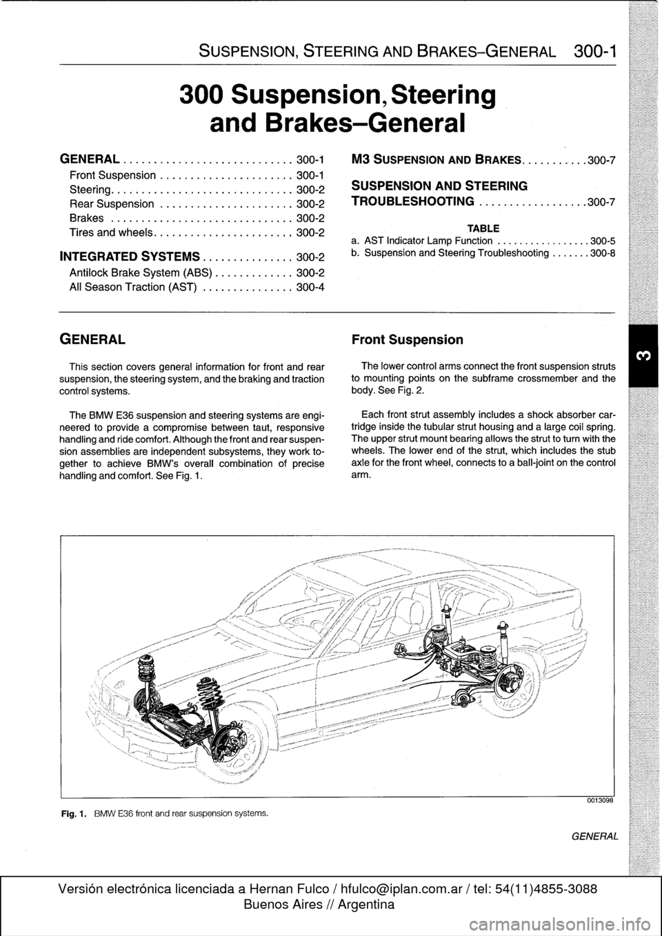
Fig
.
2
.
The
BMW
E36
suspension
and
steering
systems
are
engi-
neered
to
provide
a
compromise
between
taut,
responsive
handling
and
ride
comfort
.
Although
the
front
and
rear
suspen-
sion
assemblies
are
independent
subsystems,
they
work
to-
gether
to
achieve
BMW's
overall
combination
of
precise
handling
and
comfort
.
See
Fig
.
1
.
Fig
.
1
.
BMW
E36
front
and
rear
suspension
systems
.
Each
front
strut
assembly
includes
a
shock
absorber
car-
tridgeinside
the
tubular
strut
housing
and
a
large
coil
spring
.
The
upper
strut
mount
bearing
allows
the
strutto
turnwith
the
wheels
.
The
lower
end
of
the
strut,
which
includes
the
stub
axle
for
the
front
wheel,
connects
to
a
ball-joint
on
the
control
arm
.
0013098
GENERAL
Page 250 of 759
300-2
SUSPENSION,
STEERING
AND
BRAKES-GENERAL
Steering
INTEGRATED
SYSTEMS
The
steering
linkage
connects
the
rack-and-pinion
unit
through
tie
rodsto
the
steering
arms
.
The
tie
rod
ends
allow
the
wheels
to
pivot
and
react
to
suspension
travel
.
Rear
Suspension
The
rear
axle
carrier
is
the
main
mounting
point
for
the
final
drive
housing
and
the
rear
suspension
components
.
Trailing
arms
locatethe
rear
wheels
and
anchorthe
springs,
shocks
and
stabilizer
bar
.
Driveaxies
with
constant-velocity
(CV)
joints
at
both
ends
transfer
power
from
the
differential
to
the
road
wheels
.
The
differential
is
mounted
to
the
rearaxle
carrier
through
rubber
mountsand
bushings
to
hele
isolate
drivetrain
noise
and
vibration
.
Brakes
E36
cars
areequipped
with
power
disc
brakes
with
an
inte-
gral
antilock
brakes
(ABS)
.
The
parking
brake
is
a
dual-drum
system
integrated
with
the
rear
brake
rotors
.
See
Fig
.
3
.
Power
assist
is
provided
by
a
vacuum
booster
when
the
en-
gine
is
running
.
The
brakepedal
pushrod
is
connected
directly
to
the
master
cylinder,
so
failure
of
the
vacuum
booster
does
not
normally
result
in
total
brake
failure
.
0012124
Each
disc
brakeuses
a
caliper
with
a
single
hydraulic
cylin-
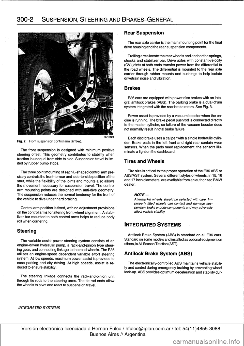
Fig
.
2
.
Front
suspension
control
arm
(arrow)
.
der
.
Brake
pads
in
the
left
front
and
right
rear
contain
wear
sensors
.
When
the
padsneed
replacement,the
sensors
illu-
The
front
suspension
is
designed
with
minimum
positive
minate
a
light
on
the
dashboard
.
steering
offset
.
This
geometry
contributes
to
stability
when
traction
is
unequalfrom
side
to
side
.
Suspension
travel
is
lim-
Tires
and
Wheels
ited
by
rubber
bump
stops
.
The
three
point
mounting
of
each
L-shaped
control
arm
ere-
Tiresize
is
critica¡
to
the
proper
operatíon
of
the
E36
ABS
or
cisely
controls
the
front-to-rear
and
side-to-side
position
of
the
ABS/AST
system
.
Severa¡
different
styles
of
wheels,
in
15,16
strut,
while
the
flexibility
of
the
joints
and
mounts
alsoallows
and
17
inch
diameters,
are
available
from
an
authorized
BMW
the
movement
necessary
for
suspension
travel
.
The
control
dealer
.
arm
mounting
points
are
designed
with
anti-dive
geometry
.
The
suspension
reduces
the
normaltendency
for
the
front
of
NOTE-
the
vehicle
to
dive
under
hard
braking
.
Aftermarket
wheelsshould
be
selected
wlth
care
.
Im-
properly
fitted
wheels
can
contact
anddamage
sus
Control
arm
position
is
fixed,
with
no
adjustment
provisions
pension,
brakeorbodycomponentsandmayadversely
on
the
control
arms
for
alter¡ng
front
wheel
al
ignment
.
A
stabi-
affect
vehicle
stability
.
lizer
bar
mounted
to
both
control
arms
heles
to
reduce
body
rol¡
whencomering
.
INTEGRATED
SYSTEMS
Antilock
Brake
System
(ABS)
is
standard
on
all
E36
cars
.
The
variable-assist
power
steering
system
consists
of
an
Standard
on
some
models
and
installed
as
optional
equipment
on
engine-driven
hydraulic
pump,
a
rack-and-pinion
type
steer-
others,
is
All
Season
Traction
(AST)
.
ing
gear,
and
connecting
linkage
to
the
road
wheels
.
TheE36
utilizes
an
engine-speed
dependent
variable
effort
steering
Antilock
Brake
System
(ABS)
system
.
At
low
speeds,
maximum
power
assist
is
provided
to
ease
parking
and
city
driving
.
Athigh
speeds,
assist
is
re-
The
electronically-controlled
ABS
maintains
vehícle
stabili
duced
to
ensure
stability
.
ty
and
control
during
emergency
braking
by
preventing
wheel
lock-up
.
ABS
provides
optimum
deceleration
and
stability
dur-