On-board computer BMW 328i 1995 E36 Workshop Manual
[x] Cancel search | Manufacturer: BMW, Model Year: 1995, Model line: 328i, Model: BMW 328i 1995 E36Pages: 759
Page 175 of 759
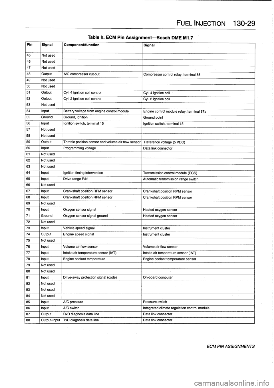
Tableh
.
ECM
Pin
Assignment--Bosch
DME
M1
.7
Pin
1
Signal
1
Component/function
1
Signal
45
Notused
46
Notused
47
Notused
48
Output
A/C
compressor
cut-out
Compressor
control
relay,
terminal
85
49
Notused
50
Notused
51
Output
Cyl
.
4
ignition
coil
control
Cyl
.
4
ignition
coil
52
Output
Cyl
.
2
ignition
coil
control
Cyl
.
2
ignition
coil
53
Not
used
54
Input
Battery
voltage
from
engine
control
module
Engine
control
module
relay,
terminal
87a
55
Ground
Ground,
ignition
Ground
point
56
Input
Ignition
switch,
terminal
15
Ignition
switch,
terminal
15
57
Notused
58
Not
used
59
Output
Throttleposition
sensor
and
volume
air
flow
sensor
Reference
voltage
(5
VDC)
60
Input
Programming
voltage
Data
link
connector
61
Notused
62
Notused
63
Notused
64
Input
Ignition
timing
intervention
Transmission
control
module
(EGS)
65
Input
Drive
range
P/N
Automatic
transmission
range
switch
66
Notused
67
Input
Crankshaft
position
RPM
sensor
Crankshaft
position
RPM
sensor
68
Input
Crankshaft
position
RPM
sensor
Crankshaft
position
RPM
sensor
69
Notused
70
Input
Oxygen
sensor
signal
Heated
oxygen
sensor
71
Ground
Oxygen
sensor
signal
ground
Heated
oxygen
sensor
72
Notused
73
Input
Vehicle
speed
signal
Instrument
cluster
74
Output
Engine
speed
signal
Instrument
cluster
75
Not
used
76
Input
Volume
air
flow
sensor
Volume
air
flow
sensor
77
Input
Intake
air
temperature
sensor
(IAT)
Intake
air
temperature
sensor
(IAT)
78
Input
Engine
coolant
temperature
Engine
coolant
temperature
sensor
79
Notused
80
Not
used
81
Input
Drive-away
protection
signal
(code)
On-boardcomputer
82
Not
used
83
Notused
84
Not
used
85
Input
A/C
pressure
Pressure
switch
86
Input
A/C
switch
Integrated
climate
regulation
control
module
87
Output
RxD
diagnosisdata
line
Data
link
connector
88
Output-Input
TxD
diagnosisdata
line
l
Data
link
connector
FUEL
INJECTION
130-
2
9
ECM
PIN
ASSIGNMENTS
Page 177 of 759
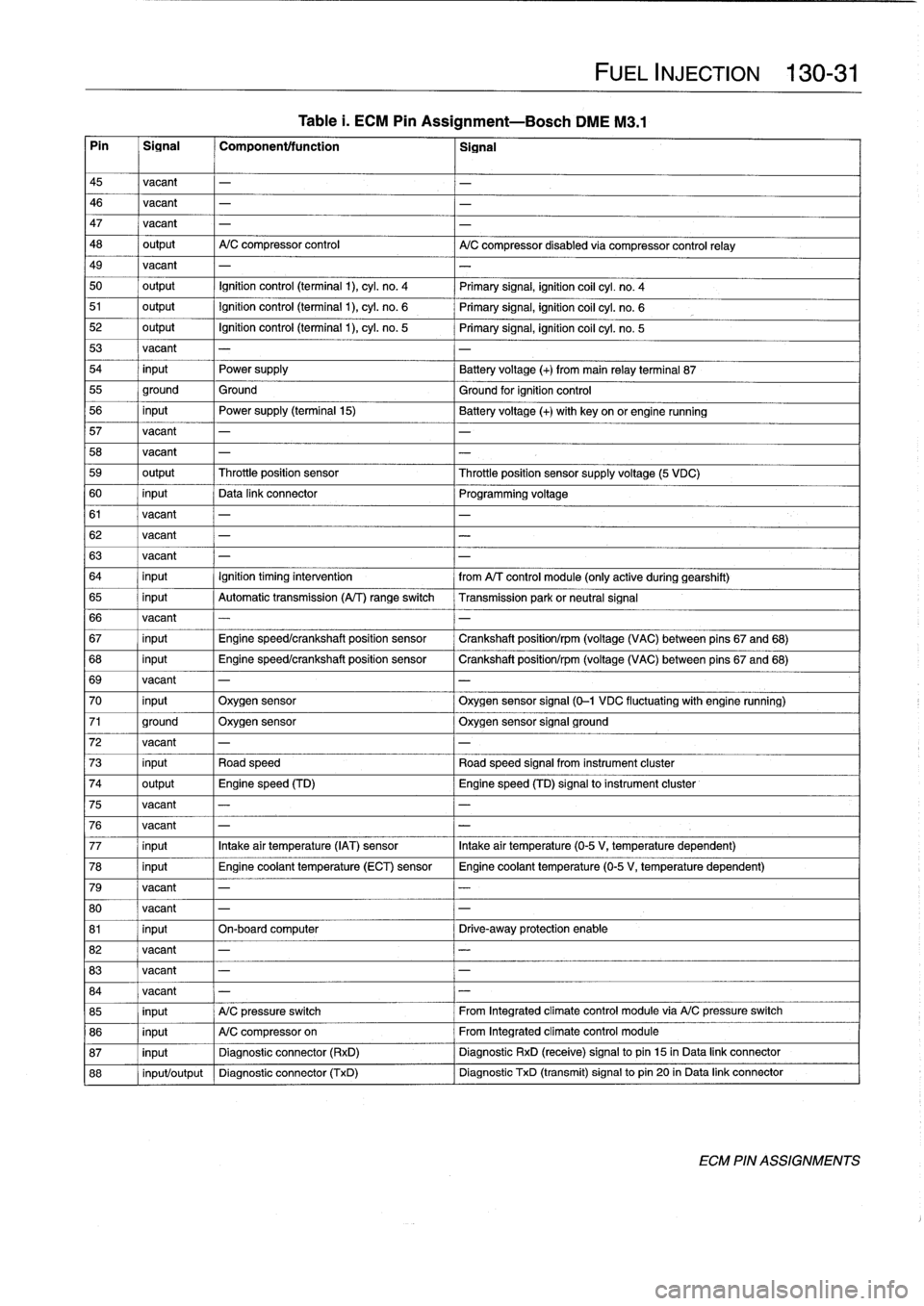
Table
i
.
ECM
Pin
Assignment-Bosch
DME
M3
.1
Pin
Signal
Component/function
2
ignal
FUEL
INJECTION
130-
3
1
45
vacant
-
46
vacant
-
-
47
vacant
-
-
48
output
A/C
compressor
control
A/C
compressor
disabled
via
compressor
control
relay
49
vacant
-
-
50
output
Ignition
control
(terminal
1),cyl
.
n
o
.
4
Primary
signal,
ignition
coil
cyl
.
n
o
.
4
51
output
Ignition
control
(terminal
1),cyl
.
n
o
.
6
Primary
signal,
ignition
coil
cyl
.
no
.
6
52
output
Ignition
control
(terminal
1),cyl
.
n
o
.
5
Primary
signal,
ignitioncoil
cyl
.
no
.
5
53
vacant
-
54
input
Power
supply
Battery
voltage
(+)
from
main
relay
terminal
87
55
ground
Ground
Ground
for
ignition
control
56
input
Power
supply
(terminal
15)
Batteryvoltage
(+)
with
key
on
or
engine
running
57
vacant
-
-
58
vacant
-
-
59
output
Throttleposition
sensor
Throttleposition
sensorsupply
voltage
(5
VDC)
60
input
Data
link
connector
Programming
voltage
61
vacant
-
-
62
vacant
-
-
63
vacant
-
-
64
input
Ignition
timing
intervention
from
A/T
control
module
(only
active
during
gearshift)
65
input
Automatic
transmission
(A/T)
range
switch
Transmission
park
or
neutral
signal
66
vacant
-
-
67
input
Engine
speed/crankshaft
position
sensor
Crankshaft
position/rpm
(voltage
(VAC)
between
pins
67
and
68)
68
input
Engine
speed/crankshaft
position
sensor
Crankshaft
position/rpm
(voltage
(VAC)
between
pins
67
and
68)
69
vacant
-
-
70
input
Oxygen
sensor
Oxygen
sensor
signal
(0-1
VDC
fluctuating
with
engine
running)
71
ground
Oxygen
sensor
Oxygen
sensor
signal
ground
72
vacant
-
-
73
input
Road
speed
Road
speed
signal
from
instrument
cluster
74
output
Engine
speed
(TD)
Engine
speed
(TD)
signalto
instrument
cluster
75
vacant
-
-
76
vacant
-
-
77
input
Intakeair
temperature
(IAT)
sensor
Intake
air
temperature
(0-5
V,
temperaturedependent)
78
input
Engine
coolant
temperature
(ECT)
sensor
Engine
coolant
temperature
(0-5V,
temperature
dependent)
79
vacant
-
-
80
vacant
-
-
81
input
On-boardcomputer
Drive-away
protection
enable
82
vacant
-
-
83
vacant
-
-
84
vacant
-
-
85
input
A/C
pressure
switch
From
Integrated
climate
control
module
via
A/C
pressure
switch
86
input
A/C
compressor
on
From
Integrated
climate
control
module
87
input
Diagnostic
connector
(RxD)
Diagnostic
RxD
(receive)signal
to
pin
15
in
Data
link
connector
88
input/output
Diagnostic
connector
(TxD)
Diagnostic
TxD
(transmit)
signal
to
pin
20
in
Data
link
connector
ECM
PIN
ASSIGNMENTS
Page 179 of 759
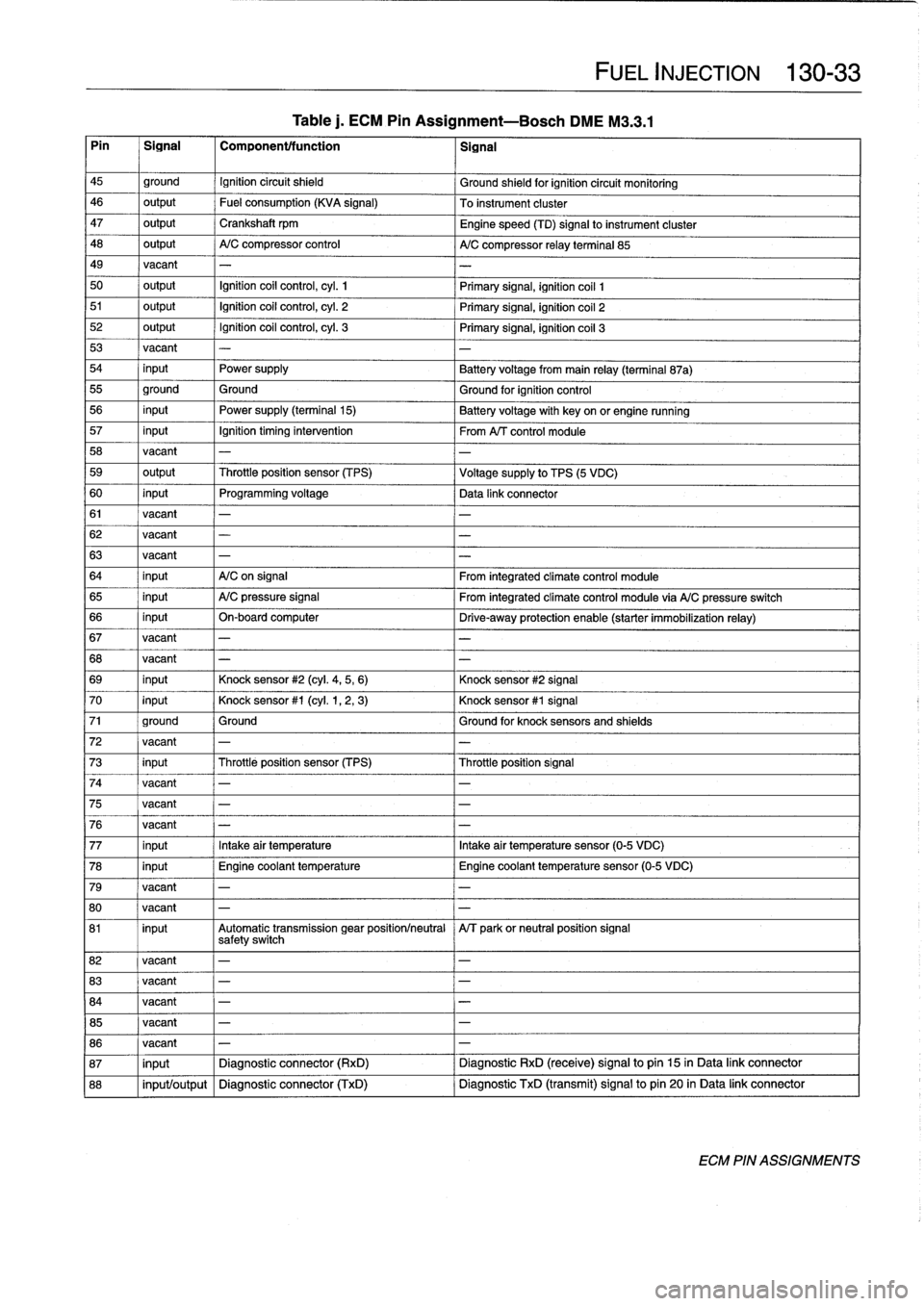
Table
j.
ECM
Pin
Assignment-Bosch
DME
M3
.3
.1
Pin
~
Signal
1
Componentffunction
1
signal
FUEL
INJECTION
130-
33
45
ground
Ignition
circuit
shield
Ground
shieldfor
ignition
circuit
monitoring
46
output
Fuel
consumption
(KVA
signal)
To
instrument
cluster
47
output
Crankshaft
rpm
Engine
speed
(TD)
signal
to
instrument
cluster
48
output
A/C
compressor
control
A/C
compressor
relay
terminal
85
49
vacant
-
-
50
output
Ignition
coil
control,
cyl
.
1
Primary
signal,
ignition
coil
1
51
output
Ignition
coil
control,
cyl
.
2
Primary
signal,
ignition
coil
2
52
output
Ignition
coil
control,
cyl
.
3
Primary
signal,
ignition
coil
3
53
vacant
-
-
54
input
Power
supply
Battery
voltagefrom
main
relay
(terminal
87a)
55
ground
Ground
Ground
for
ignition
control
56
input
Power
supply
(terminal15)
Batteryvoltage
with
key
on
or
engine
running
57
input
Ignition
timing
intervention
From
A/T
control
module
58
vacant
-
-
59
output
Throttleposition
sensor
(TPS)
Voltage
supply
to
TPS
(5
VDC)
60
input
Programming
voltage
Data
link
connector
61
vacant
-
-
62
vacant
-
-
63
vacant
-
-
64
input
A/C
on
signal
From
integrated
climate
control
module
65
input
A/C
pressure
signal
From
integrated
climate
control
module
via
A/C
pressure
switch
66
input
On-board
computer
Drive-away
protection
enable
(starter
immobilization
relay)
67
vacant
-
-
68
vacant
-
-
69
input
Knock
sensor
#2
(cyl
.
4,5,
6)
Knock
sensor
#2
signal
70
input
Knock
sensor
#1
(cyl
.
1,2,
3)
Knock
sensor
#1
signal
71
ground
Ground
Ground
for
knock
sensors
and
shields
72
vacant
-
-
73
input
Throttleposition
sensor
(TPS)
Throttleposition
signal
74
vacant
-
75
vacant
-
-
76
vacant
-
77
input
Intakeair
temperatura
Intakeair
temperatura
sensor
(0-5
VDC)
78
input
Engine
coolant
temperature
Engine
coolant
temperature
sensor
(0-5
VDC)
79
vacant
-
80
vacant
-
-
81
input
Automatic
transmission
gear
positionlneutral
A/T
parkor
neutral
position
signal
safetyswitch
82
vacant
-
-
83
vacant
-
-
84
vacant
-
-
85
vacant
-
-
86
vacant
-
-
87
input
Diagnostic
connector
(RxD)
Diagnostic
RxD
(receive)
signal
to
pin
15
in
Data
link
connector
88
input/output
Diagnostic
connector
(TxD)
Diagnostic
TxD
(transmit)
signal
to
pin
20
in
Data
link
connector
ECM
PIN
ASSIGNMENTS
Page 181 of 759
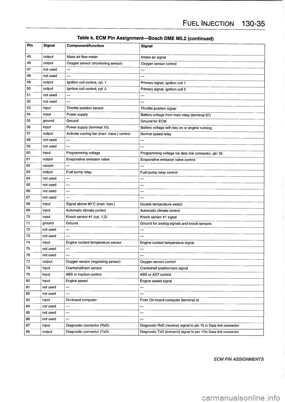
Table
k
.
ECM
Pin
Assignment-Bosch
DME
M5
.2
(continued)
Pin
I
Signal
1
Componentltunction
1
Signal
45
I
output
I
Mass
air
flow
meter
I
Intake
airSignal
46
output
Oxygen
sensor
(monitoring
sensor)
Oxygen
sensor
control
47
not
used
-
48
not
used
-
49
output
Ignition
coil
control,
cyl
.
1
Primary
signal,
ignition
coil
1
50
output
Ignition
coil
control,
cyl
.
2
Primary
signal,
ignition
coil
2
51
not
used
-
52
not
used
-
53
input
Throttleposition
sensor
Throttleposition
Signal
54
input
Power
supply
Batteryvoltage
from
main
relay
(terminal
87)
55
ground
Ground
Ground
for
ECM
56
input
Power
supply
(terminal
15)
Battery
voltage
with
key
on
or
engine
running
57
output
Activate
cooling
fan
(man
.
trans
.)
control
Normal
speed
relay
58
not
used
-
-
59
not
used
-
-
60
input
Programming
voltage
Programming
voltage
via
data
link
connector,
pin
18
61
output
Evaporative
emissionvalve
Evaporative
emission
valve
control
62
vacant
-
-
63
output
Fuel
pump
relay
Fuel
pump
relay
control
64
not
used
-
65
not
used
-
-
66
not
used
-
-
67
not
used
-
-
68
input
Signal
above
80°C(man
.
tran
.)
Double
temperature
switch
69
input
Automatic
climate
control
Automatíc
climate
control
70
input
Knock
sensor
#1
(cyl
.
1,2)
Knock
sensor
#1
Signal
71
ground
Ground
Ground
for
analog
signals
and
knock
sensors
72
not
used
-
-
73
not
used
-
-
74
input
Engine
coolant
temperature
sensor
Engine
coolant
temperatura
Signal
75
not
used
-
-
76
not
used
-
-
77
output
Oxygen
sensor
(regulating
sensor)
Oxygen
sensor
control
78
input
Crankshaft/rpm
sensor
Crankshaft
position/rpmSignal
79
input
ABS
or
traction
control
ABS
or
AST
control
80
input
Engine
speed
Engine
speed
Signal
81
not
used
-
-
82
not
used
-
-
FUEL
INJECTION
130-
3
5
83
input
On-board
computar
From
On-boardcomputer
(terminal
4)
84
not
used
-
-
85
not
used
-
-
86
not
used
-
-
87
input
Diagnostic
connector
(RxD)
Diagnostic
RxD
(receive)signal
to
pin
15
in
Data
link
connector
88
output
I
Diagnostic
connector
(TxD)
Diagnostic
TxD
(transmit)
signal
to
pin
17in
Data
link
connector
ECM
PIN
ASSIGNMENTS
Page 306 of 759
400-
4
BODY-GENERAL
INTERIOR
EQUIPMENT
E36
interiors
have
a
unique
character,
with
a
combínation
of
sporty
features
and
innovative
design
.
Al¡
body
versions
were
made
in
a
wide
choice
of
interior
and
exterior
colors
.
New
colors
with
matching
leather
and/or
fabric
upholstery
were
in-
troduced
for
each
model
year,
including
light-alloy
wheels
in
new
designs
.
Driving
comfort
is
enhanced
by
power
steering,
tilt
steering
wheel
(optional),
height-adjustable
front
seats,
and
electrical-
ly
adjustable
and
heated
rear-view
mirrors
.
Inside
thecar
there
are
reading
lights
at
four
seating
positions
.
Seats
and
Seat
Belts
NOTE-
Theseat
base
usedon
cars
with
pyrotechnic
seatbelt
Anatom¡cal
ly-correct
seats
are
constructed
from
polyure-
tensioners
is
not
interchangeable
with
the
earlier
seat
thane
foam
containing
areas
or
"zones"
of
different
firmness
.
base
.
The
seat
bases
have
steel
springs
for
added
support
and
strength
.
The
power
seats
are
provided
with
conveniently
lo-
Instruments
and
Controls
cated
switches
along
the
outside
edge
of
the
seat
.
Heated
seats
are
an
option
in
all
models
.
See
520
Seats
for
more
de-
Everything
in
the
interior
passenger
compartment
essential
tails
.
to
the
driver
is
logically
grouped
and
easy
to
reach
.
Al¡
instru-
ments
and
controls
havebeen
arranged
ergonomically
and
The
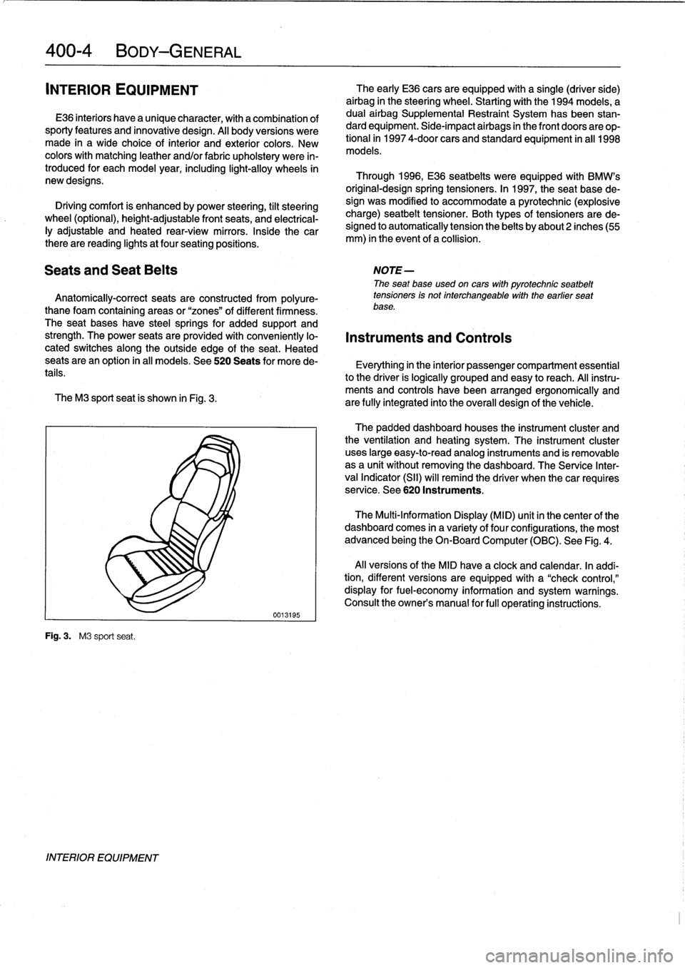
M3
sport
seat
is
shown
in
Fig
.
3
.
are
fully
integrated
into
the
overall
design
of
the
vehicle
.
Fig
.
3
.
M3
sport
seat
.
INTERIOR
EQUIPMENT
0013195
The
early
E36
cars
areequipped
with
a
single
(driver
side)
airbag
in
the
steering
wheel
.
Startingwith
the
1994
models,
a
dual
airbag
Supplemental
Restraint
System
has
been
stan-
dard
equipment
.
Side-impact
airbags
in
the
front
doors
are
op-
tional
in
1997
4-door
cars
and
standard
equipment
in
all
1998
models
.
Through
1996,
E36
seatbelts
were
equipped
with
BMW's
original-designspring
tensioners
.
In
1997,
the
seat
base
de-
sign
was
modified
to
accommodate
a
pyrotechnic
(explosive
charge)
seatbelt
tensioner
.
Both
types
of
tensioners
arede-
signed
to
automatically
tension
the
belts
by
about2
inches(55
mm)
in
the
event
of
a
collision
.
The
padded
dashboard
houses
the
instrument
cluster
and
the
ventilation
and
heating
system
.
The
instrument
cluster
uses
large
easy-to-read
analog
instruments
and
is
removable
as
a
unit
without
removing
the
dashboard
.
The
Service
Inter-
val
Indicator
(SII)
will
remind
the
driver
when
thecar
requires
service
.
See
620
Instruments
.
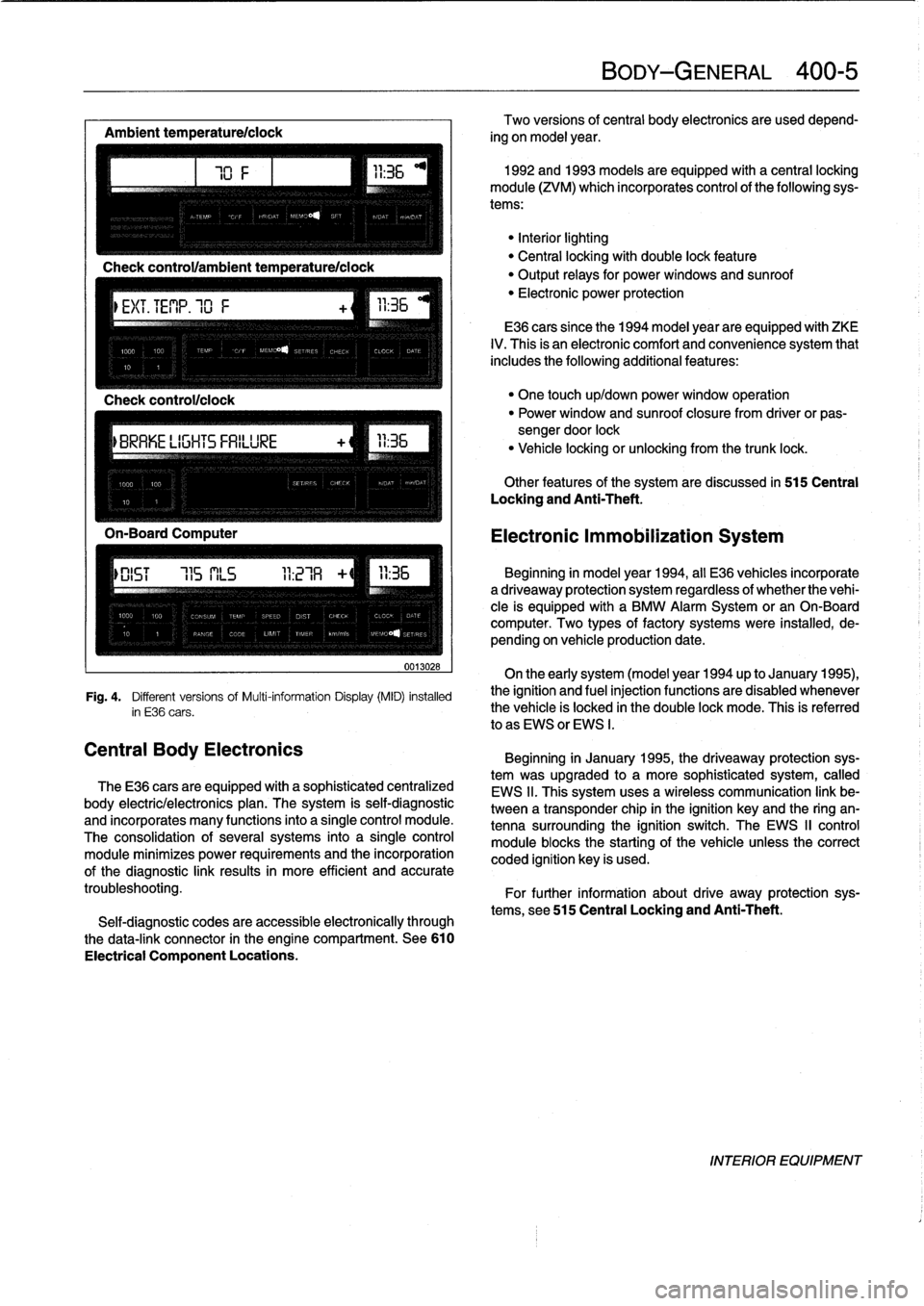
The
Multi-Information
Display
(MID)
unit
in
thecenter
of
the
dashboard
comes
in
a
variety
of
four
configurations,
the
most
advanced
being
the
On-Board
Computer
(OBC)
.
See
Fig
.
4
.
Al¡
versions
of
the
MID
have
a
clock
and
calendar
.
In
addi-
tion,
different
versions
areequipped
with
a
"check
control,"
display
for
fuel-economy
information
and
system
warnings
.
Consult
the
owner's
manual
for
fui¡
operating
instructions
.
Page 307 of 759
Ambient
temperaturelclock
MÍM
Aa
.Mi}rm
-Mil"
IMua~naa~u~itacar
"
za
.~
Central
Body
Electronics
0013028
Fig
.
4
.
Different
versionsof
Multi-information
Display(MID)
installed
in
E36
cars
.
The
E36
cars
are
equipped
with
a
sophisticated
centralized
body
electric/electronics
plan
.
The
system
is
self-diagnostic
and
incorporates
many
functions
into
a
single
control
module
.
The
consolidation
of
several
systems
into
a
single
control
module
minimizes
power
requirements
and
the
incorporation
of
the
diagnostic
link
results
in
more
efficient
and
accurate
troubleshooting
.
Self-diagnostic
codes
are
accessible
electronically
through
the
data-link
connector
in
the
engine
compartment
.
See610
Electrical
Component
Locations
.
BODY-GENERAL
400-
5
Two
versions
of
central
body
electronics
are
used
depend-
ing
on
model
year
.
1992
and
1993
models
are
equipped
with
a
central
locking
module
(ZVM)
which
incorporates
control
of
the
following
sys-
tems
:
"Interiorlighting
"
Central
locking
with
double
lock
feature
"
Output
relays
for
powerwindows
and
sunroof
"
Electronic
power
protection
E36
cars
since
the
1994
model
year
are
equipped
with
ZKE
IV
.
This
is
an
electronic
comfort
and
convenience
system
that
includes
the
following
additional
features
:
"
One
touch
up/down
power
window
operation
"
Power
window
and
sunroof
closure
from
driver
or
pas-
sengerdoor
lock
"
Vehicle
locking
or
unlocking
from
the
trunk
lock
.
Other
features
of
the
system
are
discussed
in
515
Central
Locking
and
Anti-Theft
.
Electronic
Immobilization
System
Beginning
in
model
year
1994,
all
E36
vehicles
incorporate
adriveaway
protection
system
regardless
of
whether
the
vehi-
cle
is
equipped
with
a
BMW
Alarm
System
or
an
On-Board
computer
.
Two
types
of
factory
systems
were
installed,
de-
pending
on
vehicle
production
date
.
On
the
early
system
(model
year
1994
up
to
January
1995),
the
ignition
and
fuel
injection
functions
are
disabled
whenever
the
vehicle
is
locked
in
the
double
lock
mode
.
This
is
referred
lo
as
EWS
or
EWS
I
.
Beginning
in
January
1995,
the
driveaway
protection
sys-
tem
was
upgraded
to
a
more
sophisticated
system,
called
EWS
II
.
This
system
uses
a
wireless
communication
link
be-
tween
a
transponder
chip
in
the
ignition
keyand
the
ring
an-
tenna
surrounding
the
ignition
switch
.
The
EWS
II
control
module
blocksthe
starting
of
the
vehicle
unlessthe
correct
coded
ignition
key
is
used
.
For
further
information
about
drive
away
protection
sys-
tems,
see
515
Central
Locking
and
Anti-Theft
.
INTERIOR
EQUIPMENT
Page 402 of 759
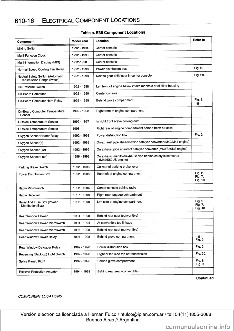
610-16
ELECTRICAL
COMPONENT
LOCATIONS
Component
Model
Year
Location
Refer
to
MixingSwitch
1992-1994
Center
console
Multi-Function
Clock
1992-1998
Center
console
Multi-information
Display
(MDI)
1992-1998
Center
console
Normal
Speed
Cooling
Fan
Relay
1992-1998
Power
distribution
box
Fig
.
2
.
Neutral
SafetySwitch
(Automatic
1992-1998
Next
to
gear
shift
lever
in
center
console
Fig
.
29
.
Transmission
Range
Switch)
Oil
Pressure
Switch
1992-1998
Left
front
of
engine
below
intake
manifold
at
oil
filter
housing
On-Board
Computer
1992-1998
Center
console
On-BoardComputerHorn
Relay
1992-1998
Behind
glove
compartment
Fig
.
8
.
Fig
.
9
.
On-Board
Computer
Temperature
11992-1998
I
Right
front
of
engine
compartment
Sensor
Outside
Temperature
Sensor
1992-1997
Inright
front
brake
cooling
duct
Outside
Temperature
Sensor
1998
Right
rear
of
engine
compartment
behind
fresh
air
cowl
Oxygen
Sensor
HeaterRelay
1992-1998
Power
distribution
box
Fig
.
2
.
Oxygen
Sensor(s)
1992-1998
On
exhaust
pipe
ahead/behind
catalytic
converter
(M42/M44
engine)
Oxygen
Sensor
(x2)
1992-1995
On
exhaust
pipe
ahead
of
catalytic
converter
(M50/S50US
engine)
Oxygen
Sensors
(x4)
1996-1998
On
exhaust
manifold/exhaust
pípe
behind
catalytic
converter
(M52/S52US
engine)
Parking
Brake
Switch
1
1992-1998
I
On
rear
of
parking
brake
lever
Power
Distribution
Box
11992-1998
I
Rear
left
of
engine
compartment
I
Fig
.
2
.
Fig
.
7
.
Fig
.
10
.
Radio
Microswitch
1992
-
1996
Center
console
behind
radio
Radio
Receíver
1
1997-1998
1
Right
rear
luggage
compartment
Relay
And
Fuse
Box
(Power
1992-1998
I
Left
side
of
engine
compartment
I
Fig
.
2
.
Distribution
Box)
Fig
.
7
.
Fig
.
10
.
Rear
Window
Blower
1994-1998
Behind
rear
seat
(convertible)
Rear
Window
Blower
Microswitch
1994-1994
At
convertible
top
linkage
Rear
Window
Blower
Microswitch
1995-1998
Behind
rear
seat
(convertible)
Rear
Window
BlowerRelay
11994-1998
Behind
glove
compartment
Fig
.
8
.
Fig
.
9
.
Fig
.
2
.
Fig
.
30
.
Fig
.
8
.
Rear
Window
DefoggerRelay
Reversing
(Back-up)
Light
Switch
SplicePanel,
Right
Rollover
Protection
Actuator
11994-1998
COMPONENT
LOCATIONS
Table
a
.
E36
Component
Locations
1992-1998
1992-1998
1992-1998
Power
distribution
box
Right
or
left
side
top
of
transmission
Behind
glove
compartment
Behind
rear
seat
(convertible)
Fig
.
9
.
Continued
Page 406 of 759
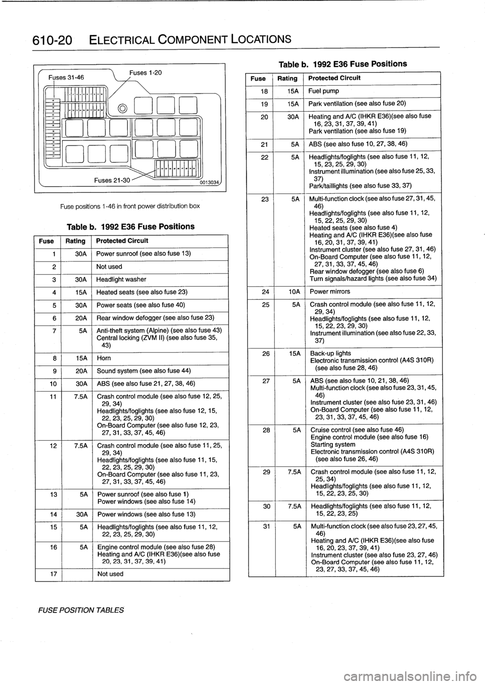
610-20
ELECTRICAL
COMPONENT
LOCATIONS
Fuses
31-46
o_
~oomoo
ommmo~
8
I
15A
I
Horn
Fuses21-30
Fuses
1-20
Fuse
positions
1-46
in
front
power
distribution
box
Table
b
.
1992
E36
Fuse
Positions
Fuse
1
Rating
1
Protected
Circuit
1
1
30A
1
Power
sunroof
(see
also
fuse
13)
2
I
I
Not
used
3
1
30A
1
Headlight
washer
(a
El
1
:1
El
4
1
15A
1
Heated
seats
(see
also
fuse
23)
5
1
30A
1
Power
seats
(see
also
fuse
40)
6
1
20A
1
Rear
window
defogger
(see
also
fuse
23)
7
5A
~
Anti-theft
system
(Alpine)
(see
also
fuse
43)
Central
locking
(ZVM
II)
(see
also
f
use
35,43)
9
(
20A
1
Sound
system
(see
also
fuse
44)
10
1
30A
1
ABS
(see
also
f
use
21,
27,
38,
46)
11
7
.5A
Crash
control
module
(seealso
fuse
12,25,
29,34)
Headlights/foglights
(see
also
fuse
12,15,22,23,
25,29,
30)
On-BoardComputer
(seealsofuse
12,
23,27,31,
33,37,
45,
46)
12
7
.5A
Crash
control
module
(see
also
f
use
11,
25,
29,34)
Headlights/foglights
(seealsofuse
11,15,
22,
23,25,
29,
30)
On-BoardComputer
(see
also
fuse
11,
23,27,
31,33,
37,45,
46)
13
5A
Power
sunroof
(see
also
fuse
1)
Power
windows
(see
also
f
use
14)
14
j
30A
1
Power
windows
(see
also
fuse
13)
15
5A
Headlights/foglights
(see
also
fuse
11,
12,22,
23,
25,29,
30)
16
5A
~
Engine
control
module
(seealsofuse
28)
Heating
andA/C
(IHKR
E36)(see
alsofuse
20,
23,
31,37,
39,
41)
17
I
I
Notused
FUSE
POSITION
TABLES
0013034
Table
b
.
1992
E36
Fuse
Positions
Fuse
Rating
Protected
Circult
18
1
15A
1
Fuel
pump
19
j
15A
1
Park
ventilation
(see
also
fuse
20)
20
30A
~
Heating
andA/C
(IHKR
E36)(see
alsofuse
16,23,31,37,39,
41)
Park
ventilation
(see
also
f
use
19)
21
1
5A
{
ABS
(see
also
fuse
10,27,
38,46)
22
5A
Headlights/foglights
(see
also
f
use
11,12,15,
23,
25,29,
30)
Instrument
illumination
(see
also
fuse
25,33,
37)
Park/taillights
(seealsofuse
33,
37)
23
5A
Multi-function
clock
(see
also
fuse
27,
31,
45,
46)
Headlights/foglights
(see
also
fuse
11,12,15,22,25,
29,30)
Heated
seats
(seealsofuse
4)
Heating
andA/C
(IHKR
E36)(see
alsofuse
16,20,31,37,39,
41)
Instrument
cluster
(see
also
fuse
27,31,
46)
On-Board
Computer
(seealso
fuse
11,
12,
27,31,
33,
37,45,
46)
Rear
window
defogger
(see
alsofuse
6)
Turn
signals/hazard
lights
(seealsofuse
34)
24
I
10A
I
Power
mirrors
25
5A
Crash
control
module
(see
also
f
use
11,12,
29,34)
Headlights/foglights
(see
also
fuse
11,12,15,22,23,29,
30)
Instrument
illumination
(see
also
fuse
22,
33,
37)
26
15A
~
Back-up
lights
Electronic
transmission
control
(A4S
310R)
(seealsofuse
28,46)
27
5A
ABS
(see
also
fuse
10,21,38,
46)
Multi-function
clock
(see
also
fuse
23,
31,
45,46)
Instrument
cluster
(see
also
fuse
23,
31,46)
On-BoardComputer
(see
also
fuse
11,12,23,
31,
33,37,45,
46)
28
5A
Cruise
control
(see
alsofuse
46)
Engine
control
module
(see
alsofuse
16)
Starting
system
Electronic
transmission
control
(A4S
310R)
(see
also
f
use
26,
46)
29
7
.5A
Crash
control
module
(see
also
fuse
11,12,
25,34)
Headlights/foglights
(see
also
fuse
11,12,15,22,23,
25,
30)
30
7
.5A
Headlights/foglights
(see
also
fuse
11,
12,
15,22,23,
25)
31
5A
Multi-function
clock
(see
alsofuse
23,27,
45,46)
Heating
andA/C
(IHKR
E36)(see
also
fuse
16,20,
23,
37,39,
41)
Instrument
cluster
(seealso
fuse
23,
27,46)
On-Board
Computer
(see
also
f
use
11,12,23,27,
33,
37,45,
46)
Page 407 of 759
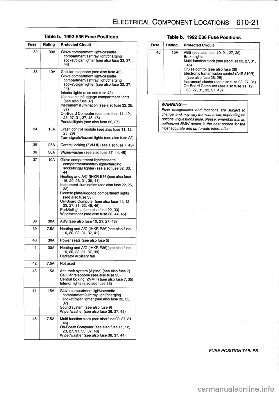
Table
b
.
1992
E36
Fuse
Positions
Table
b
.
1992
E36
Fuse
Positions
Fuse
Rating
Protected
Circuit
32
30A
Glove
compartment
light/cassette
compartmenVashtray
light/charging
socket/cigar
lighter
(see
also
fuse
33,37,
44)
33
10A
Cellular
telephone
(seealsofuse
43)
Glove
compartment
light/cassette
compartment/ashtray
IighUcharging
sockeUcigar
lighter
(seealsofuse
32,
37,
44)
Interiorlights
(also
see
fuse
43)
License
plate/luggage
compartment
lights
(see
also
f
use
37)
Instrument
íllumination
(see
also
fuse
22,25,
37)
On-Board
Computer
(see
also
fuse
11,12,23,27,31,37,45,
46)
Park/taillights
(seealso
fuse
22,
37)
34
15A
~
Crash
control
module
(see
also
fuse
11,
12,
25,29)
Turn
signals/hazard
lights
(seealsofuse
23)
35
1
25A
j
Central
locking
(ZVM
II)
(see
alsofuse
7,
43)
36
1
30A
1
Wiper/washer
(seealsofuse
37,44,
45)
37
10A
Glove
compartment
IighUcassette
compartmenVashtray
light/charging
socket/cigar
lighter
(see
also
fuse
32,33,
44)
Heating
andA/C
(IHKR
E36)(see
alsofuse
16,
20,23,31,
39,41)
Instrument
illumination
(see
also
fuse
22,25,
33)
License
plate/luggage
compartment
lights
(see
also
fuse
33)
On-Board
Computer
(see
also
fuse
11,12,23,27,31,33,45,
46)
Park/taillights
(see
alsofuse
22,
33)
Wiper/washer
(see
also
fuse
36,
44,
45)
38
1
30A
1
ABS
(see
also
fuse
10,21,27,
46)
39
7
.5A
Heating
andA/C
(IHKR
E36)(see
also
fuse
16,20,
23,
31,37,
41)
40
1
30A
1
Power
seats
(see
also
fuse
5)
41
30A
~
Heating
andA/C
(IHKR
E36)(see
alsofuse
16,20,23,
31,
37,
39)
Radiator
auxiliary
fan
42
I
7
.5A
I
Not
used
43
5A
Anti-theft
system
(Alpine)
(see
also
fuse
7)
Cellular
telephone
(seealsofuse
33)
Centrallocking
(ZVM
II)
(see
also
f
use
7,
35)
Interiorlights
(also
see
fuse
33)
44
15A
Glove
compartment
light/cassette
compartmenVashtray
light/charging
sockeUcigar
lighter
(see
also
fuse
32,
33,
37)
Sound
system
(see
also
fuse
9)
Wiper/washer
(see
also
fuse
36,37,
45)
45
7
.5A
Multi-function
clock
(see
also
fuse
23,
27,
31,
46)
On-Board
Computer
(see
also
fuse
11,12,
23,
27,31,33,
37,46)
Wiper/washer
(see
also
fuse
36,37,
44)
ELECTRICAL
COMPONENT
LOCATIONS
610-21
Fuse
Rating
Protected
Circuít
46
15A
ABS
(see
also
fuse
10,21,27,
38)
Brake
lights
Multi-function
clock
(seealso
fuse
23,27,31,
45)
Cruise
control
(see
also
fuse
28)
Electronic
transmission
control
(A4S
310R)
(see
also
f
use
26,
28)
Instrument
cluster
(seealsofuse
23,
27,31)
On-Board
Computer
(see
also
f
use
11,12,
23,
27,31,33,
37,45)
WARNING
-
Fuse
designations
and
locations
are
subject
to
change,
and
may
vary
from
car
tocar,
depending
on
options
.
If
questions
arise,
please
remember
that
an
authorized
BMW
dealer
is
the
best
source
for
the
most
accurate
and
up-to-date
information
.
FOSE
POSITION
TABLES
Page 408 of 759
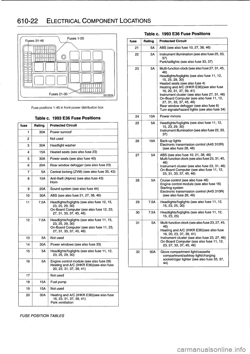
610-22
ELECTRICAL
COMPONENT
LOCATIONS
Fuses
31-46
Ylililll
milililil
Fuses
21-30
Fuse
positions
1-46
in
front
Power
distribution
box
Table
c
.
1993
E36
Fuse
Positions
fuse
1
Rating
j
Protected
Circuit
1
I
30A
I
Powersunroof
2
I
I
Not
used
Fuses
1-20
3
1
30A
1
Headlight
washer
4
1
15A
1
Heated
seats
(see
also
fuse
23)
5
1
30A
1
Power
seats
(see
also
fuse
40)
0013034
6
1
20A
1
Rear
window
defogger
(see
also
fuse
23)
5A
1
Central
locking
(ZVM)
(see
also
f
use
35,
43)
8
15A
Anti-theft
(Alpine)
(seealsofuse
43)
Horn
9
1
20A
1
Sound
system
(seealsofuse
44)
10
1
30A
1
ABS
(see
alsofuse
21,
27,
38,
46)
11
7.5A
Headlights/foglights
(see
also
fuse
12,15,23,25,29,
30)
On-Board
Computer
(see
also
fuse
12,23,27,31,33,37,
45,46)
12
7.5A
Headlights/foglights
(see
also
fuse
11,15,23,25,29,
30)
On-Board
Computer
(seealsofuse
11,
23,27,31,33,
37,
45,
46)
13
I
5A
I
Not
used
14
1
30A
1
Powerwindows
(see
also
fuse
33)
15
5A
Headlights/foglights
(seealsofuse
11,
12,
23,25,29,
30)
16
5A
~
Engine
control
module
(see
also
f
use28)
Heating
and
A/C
(IHKR
E36)(see
also
fuse
20,
23,31,
37,39,
41)
17
I
I
Notused
18
1
15A
1
Fuel
pump
19
I
15A
I
Notused
20
30A
~
Heating
and
A/C
(IHKR
E36)(see
also
fuse
16,
23,
31,37,39,
41)
Park
ventilation
FUSE
POSITION
TABLES
Tablec
.
1993
E36
Fuse
Positions
fuse
Rating
Protected
Circuit
21
1
5A
1
ABS
(seealsofuse
10,27,38,
46)
22
5A
~
Instrument
illumination
(seealsoPuse
25,
33,
37)
Park/taillights
(see
alsofuse
33,37)
23
5A
Multi-function
clock
(see
also
fuse
27,
31,
45,46)
Headlights/foglights
(see
also
f
use
11,12,
15,
25,
29,
30)
Heated
seats
(seealsofuse
4)
Heating
andA/C
(IHKR
E36)(see
alsofuse
16,
20,
31,37,
39,41)
Instrument
cluster
(seealsofuse
27,31,46)
On-Board
Computer
(see
also
fuse
11,
12,
27,
31,33,
37,45,46)
Rear
window
defogger
(see
also
fuse
6)
Turn
signals/hazard
lights
(seealso
f
use
34)
24
I
10A
I
Power
mirrors
25
5A
Headlights/foglights
(see
also
fuse
11,12,15,23,
29,
30)
Instrument
illumination
(seealso
fuse
22,33,
37)
26
10A
~
Back-up
lights
Electronic
transmission
control
(A4S
310R)
(see
also
f
use
28,
46)
27
5A
ABS
(see
also
f
use
10,21,
38,46)
Multi4unctionclock
(see
also
f
use
23,31,45,
46)
Instrument
cluster
(seealsofuse
23,31,
46)
On-Board
Computer
(see
also
fuse
11,12,
23,
31,33,37,
45,
46)
28
5A
Cruise
control
(see
alsofuse
46)
Engine
control
module
(see
also
fuse
16)
Starting
system
Electronic
transmission
control
(A4S
310R)
(see
alsofuse
26,46)
29
7
.5A
Headlights/foglights
(see
also
fuse
11,
12,
15,23,
25,30)
30
7.5A
Headlights/foglights
(seealso
fuse
11,
12,
15,23,
25)
31
5A
Multi-function
clock
(seealsofuse
23,
27,
45,
46)
Heating
and
A/C
(IHKR
E36)(see
also
fuse
16,
20,23,
37,39,
41)
Instrument
cluster
(seealsofuse
23,
27,46)
On-Board
Computer
(see
also
f
use
11,12,23,
27,33,
37,45,
46)
32
30A
Glove
compariment
light/cassette
compartment/ashtray
light/charging
socket/cigar
lighter
(seealsofuse
33,
37,
44)