o2 sensor wire BMW 328i 1997 E36 Owner's Guide
[x] Cancel search | Manufacturer: BMW, Model Year: 1997, Model line: 328i, Model: BMW 328i 1997 E36Pages: 759
Page 277 of 759
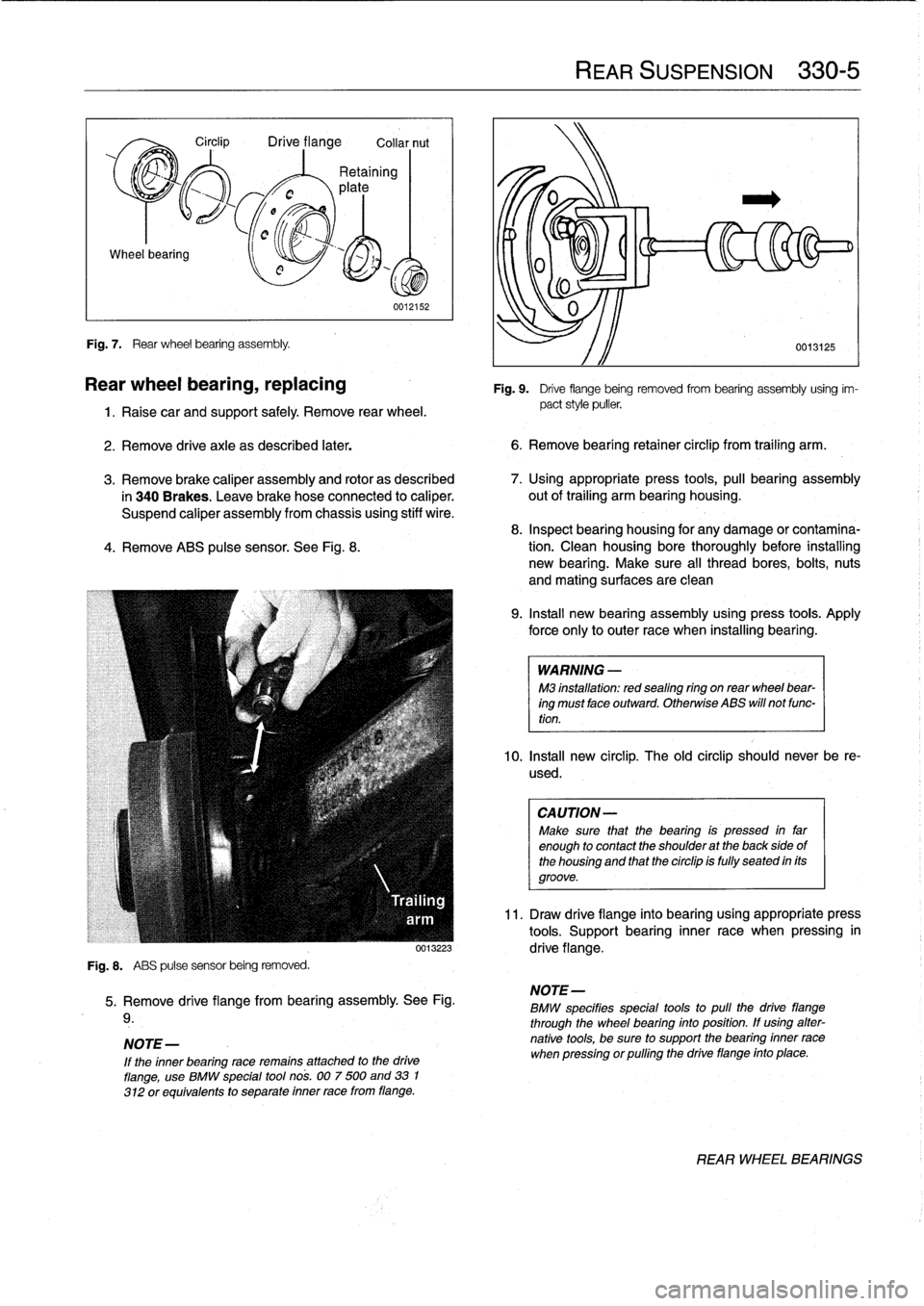
Wheel
bearing
Fig
.
7
.
Rear
wheel
bearing
assembly
.
Circlip
Drive
flange
Collar
nut
0012152
Rear
wheel
bearing,
replacing
1
.
Raise
car
and
support
safely
.
Remove
rear
wheel
.
2
.
Remove
drive
axle
as
described
later
.
6
.
Remove
bearíng
retainer
circlip
from
trailing
arm
.
3
.
Remove
brake
caliper
assembly
and
rotor
as
described
7
.
Using
appropriate
press
tools,
pull
bearing
assembly
in
340
Brakes
.
Leave
brake
hose
connected
to
caliper
.
out
of
trailing
arm
bearing
housing
.
Suspend
caliper
assembly
from
chassís
using
stiff
wire
.
8
.
Inspect
bearing
housing
for
any
damage
or
contamina
4
.
Remove
ABS
pulse
sensor
.
See
Fig
.
8
.
tion
.
Clean
housing
bore
thoroughly
before
installing
new
bearing
.
Make
sure
al¡
thread
bores,
bolts,
nuts
and
mating
surfaces
are
clean
Fig
.
8
.
ABS
pulse
sensor
being
removed
.
5
.
Remove
drive
flange
from
bearing
assembly
.
See
Fig
.
9
.
NOTE-
If
the
inner
bearing
race
remains
attached
to
the
drive
flange,
use
BMW
special
tool
nos
.
007
500
and
33
1
312
or
equivalents
to
separate
inner
race
from
flange
.
REAR
SUSPENSION
330-
5
0013125
Fig
.
9
.
Drive
flange
being
removed
from
bearing
assembly
using
im-
pact
style
puller
.
9
.
Install
new
bearing
assembly
using
press
tools
.
Apply
force
only
to
outer
race
when
installing
bearing
.
WARNING
-
M3
installation
:
redsealing
ríng
on
rear
wheel
bear-
ing
must
face
outward
.
Otherwíse
ABS
will
not
func-
tion
.
10
.
Insta¡¡
new
circlip
.
The
old
circlip
should
never
be
re-
used
.
CAUTION-
Make
sure
that
the
bearing
is
pressed
in
far
enough
to
contact
the
shoulder
at
the
back
sideof
the
housing
and
that
the
circlip
is
fully
seated
in
its
groove
.
11
.
Draw
drive
flange
into
bearing
using
appropriate
press
tools
.
Support
bearing
inner
race
when
pressing
in
0013223
drive
flange
.
NOTE-
BMW
specifies
special
tools
to
pull
the
drive
fiange
through
the
wheel
bearing
into
position
.
If
using
alter-
native
tools,
be
sure
to
support
the
bearing
inner
race
when
pressing
orpulling
the
drive
flange
finto
place
.
REARWHEEL
BEARINGS
Page 282 of 759
330-
1
0
REAR
SUSPENSION
Trailing
arm,
removing
and
installing
1
.
Raise
rear
end
of
car
and
remove
wheel
.
WARNING
-
Make
sure
that
the
car
is
firmly
supported
on
jack
standsdesigned
for
the
purpose
.
Place
the
jack
standsbeneatha
structural
chassis
point
.
Do
not
place
jack
stands
under
suspension
parts
.
2
.
Remove
drive
axle
as
described
earlier
.
3
.
Remove
brake
rotor
and
caliper
as
described
in
340
Brakes
.
Do
not
remove
brake
line
from
caliper
.
Hang
caliper
from
body
with
wire
.
4
.
Remove
parking
brakecable
frombrake
shoe
expand-
er
.
See
340
Brakes
.
5
.
Remove
rear
brake
line
bracket
from
trailing
arm
.
See
Fig
.
17
.
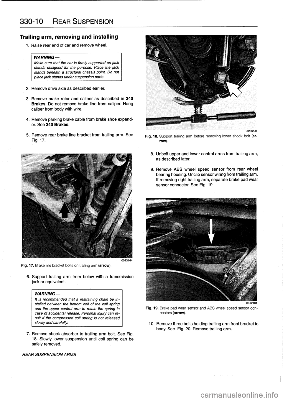
Fig
.
17
.
Brake
line
bracket
bolts
on
trailing
arm
(arrow)
.
WARNING
-
It
is
recommended
that
a
restraining
chain
be
in-
stalled
between
the
bottom
coil
of
the
coil
spring
and
the
upper
control
arm
to
retainthe
spring
in
case
of
accidentalrelease
.
Personal
injury
can
re-sult
if
the
compressed
coil
spring
is
not
released
slow1y
and
carefully
.
REAR
SUSPENSION
ARMS
6
.
Support
trailing
arm
from
below
with
a
transmission
jackorequivalent
.
7
.
Remove
shock
absorber
to
trailing
arm
bolt
.
See
Fig
.
18
.
Slowly
lower
suspension
until
coil
spring
can
be
safely
removed
.
0013220
Fig
.
18
.
Support
trailing
arm
before
removing
lower
shock
bolt
(ar-
row)
.
8
.
Unbolt
upper
and
lower
control
arms
from
trailing
arm,
as
described
later
.
9
.
Remove
ABS
wheel
speed
sensor
from
rear
wheel
bearing
housing
.
Unclip
sensor
wiríng
from
trailing
arm
.
If
removing
right
trailing
arm,
separate
brake
pad
wear
sensor
connector
.
See
Fig
.
19
.
0012104
Fig
.
19
.
Brake
pad
wear
sensor
and
ABS
wheel
speed
sensor
con-
nectors
(arrow)
.
10
.
Remove
three
bolts
holding
trailing
arm
front
bracket
to
body
.
See
Fig
.
20
.
Remove
trailing
arm
.
Page 294 of 759
340-
4
BRAKES
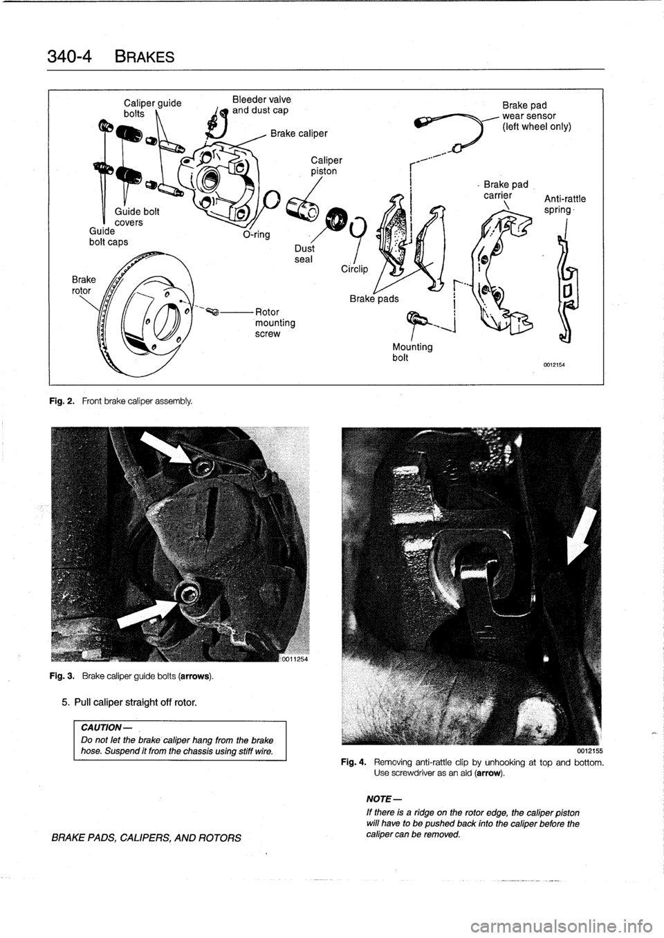
Fig
.
2
.
Front
brake
caliper
assembly
.
Bleeder
valve
and
dust
cap
Mounting
bolt
Brake
pad
wearsensor
(left
wheel
only)
-
Brake
pad
.
carrier
Anti-rattle
^_
spring-
0012154
Fig
.
3
.
Brake
caliper
guide
bolts
(arrows)
.
5
.
Pull
caliper
straight
off
rotor
.
CAUTION-
Do
not
let
the
brake
cafiper
hang
from
the
brake
hose
.
Suspend
ft
from
the
chassis
using
stiff
wire
.
BRAKE
PADS,
CALIPERS,
AND
ROTORS
0012155
Fig
.
4
.
Removing
anti-rattle
clip
by
unhooking
at
top
and
bottom
.
Use
screwdriver
asan
aid
(arrow)
.
NOTE-
If
there
is
a
ridge
on
the
rotor
edge,
the
cafiper
pfston
will
have
to
be
pushed
back
finto
the
cafiper
before
the
cafiper
can
be
removed
.
Page 302 of 759
340-
1
2
BRAKES
ABS
is
self-tested
by
the
ABS
diagnostic
unit
each
time
the
car
is
started
.
Once
the
test
is
complete,
the
ABS
dashboard
light
tucos
off
.
If
the
light
remains
lit
or
comes
on
at
any
time
during
driving,
a
system
fault
has
occurred
and
ABS
is
elec-
tronically
disabled
.
The
conventional
braking
systemremains
fully
functioning
.
ABS
Inspection
A
visual
inspection
of
the
ABS
may
help
to
locate
system
faults
.
If
no
visual
faults
can
befound
and
the
ABS
light
re-
mains
on,
have
the
system
diagnosedbyan
authorized
BMW
dealer
.
Carefully
inspect
the
entire
ABS
wiring
harness,
particularly
the
pulse
sensorharnesses
and
connectors
near
each
wheel
.
Look
for
chafing
or
damage
due
to
incorrectly
routed
wires
.
Carefully
remove
the
wheelspeed
sensors
.
Clean
the
sen-
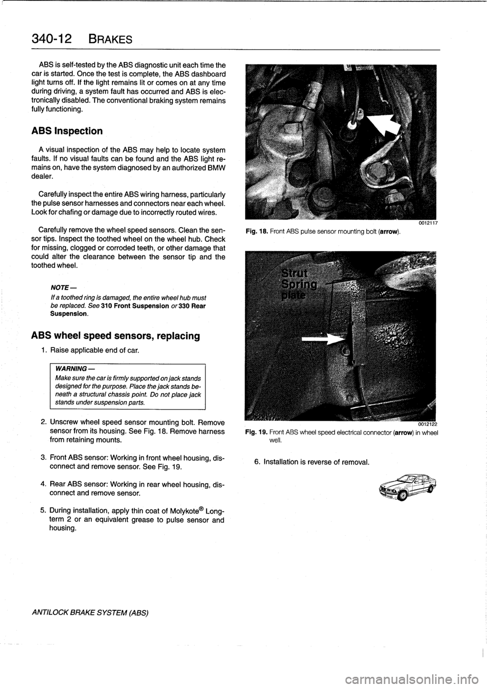
Fig
.
18
.
Front
ABS
pulse
sensor
mounting
bolt
(arrow)
.
sor
tips
.
Inspect
the
toothed
wheel
on
thewheel
hub
.
Check
for
missing,
clogged
or
corroded
teeth,
or
other
damage
that
could
alter
the
clearance
between
the
sensor
tip
and
the
toothed
wheel
.
NOTE-
If
a
toothed
ring
is
damaged,
the
entire
wheel
hub
mustbe
reptaced
.
See
310
Front
Suspension
or330
Rear
Suspension
.
ABS
wheel
speed
sensors,
replacing
1
.
Raise
applicable
end
of
car
.
WARNING
-
Make
sure
thecar
is
firmly
supportedon
jack
stands
designed
for
the
purpose
.
Place
the
jack
stands
be-
neath
a
structural
chassis
point
Do
not
place
jack
stands
under
suspension
parts
.
2
.
Unscrew
wheelspeed
sensor
mounting
bolt
.
Remove
sensor
from
its
housing
.
See
Fig
.
18
.
Remove
harnessfrom
retaining
mounts
.
3
.
Front
ABS
sensor
:
Working
in
front
wheel
housing,
dis-
connect
and
remove
sensor
.
See
Fig
.
19
.
4
.
Rear
ABS
sensor
:
Working
in
rear
wheel
housing,
dis-
connect
andremove
sensor
.
5
.
During
installation,
apply
thin
coat
of
Molykote
0
Long-
term
2
or
an
equivalent
grease
to
pulse
sensor
and
housing
.
ANTILOCK
BRAKE
SYSTEM
(ABS)
0012122
Fig
.
19
.
Front
ABS
wheel
speed
electrical
connector
(arrow)
in
wheel
well
.
6
.
Installation
is
reverse
of
removal
.
Page 385 of 759
Continuity,
checking
Short
Circuits
from
Battery
CAUTION-
Use
only
a
high
quality
digital
ohmmeter
having
high
input
impedance
when
checking
electronic
componente
.
The
internal
power
source
used
in
most
analog
(swing-need1e)
meterscan
damage
solidstate
components
.
0013239
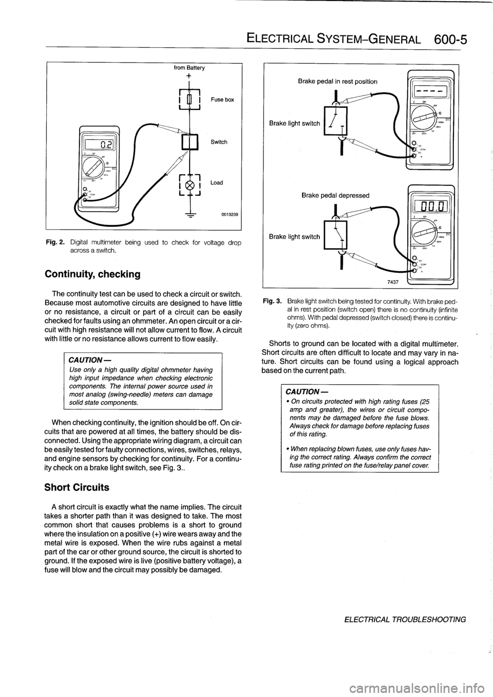
Fig
.
2
.
Digital
multimeter
being
used
to
check
for
voltage
drop
across
a
switch
.
The
continuity
test
can
beused
to
check
a
circuit
or
switch
.
Because
most
automotive
circuits
are
designed
to
have
little
or
no
resistance,
a
circuit
or
part
of
a
circuit
canbe
easily
checked
for
faults
using
an
ohmmeter
.
An
open
circuit
or
a
cir-
cuit
withhigh
resistance
will
not
allow
current
to
flow
.
A
círcuit
with
little
or
no
resistanceallows
current
to
flow
easily
.
When
checking
continuity,
the
ignition
should
be
off
.
On
cir-
cuits
that
are
powered
at
all
times,
the
battery
should
be
dis-
connected
.
Using
the
appropriate
wiring
diagram,
a
circuit
can
be
easily
tested
for
faulty
connections,
wires,
switches,
relays,
and
engine
sensorsby
checking
forcontinuity
.
For
a
continu-
ity
check
on
a
brake
light
switch,
see
Fig
.
3
..
A
short
circuit
is
exactly
what
the
narre
implies
.
The
circuit
takes
a
shorter
paththan
it
was
designed
to
take
.
The
most
common
short
that
causes
problems
is
a
short
to
ground
where
the
insulation
on
a
positive
(+)
wire
wears
away
and
the
metal
wire
is
exposed
.
When
the
wire
rubs
against
a
metal
partof
thecar
or
other
ground
source,
the
circuit
is
shorted
to
ground
.
If
the
exposed
wire
is
live
(positive
battery
voltage),
a
Puse
will
blow
and
the
circuit
may
possibly
be
damaged
.
ELECTRICAL
SYSTEM
-
GENERAL
600-
5
Brake
light
switch
Brake
pedal
in
rest
position
Q
Brake
pedal
depressed
Brake
light
switch
Fig
.
3
.
Brake
light
switchbeing
tested
for
continuity
.
With
brake
ped-
alin
rest
position
(switch
open)
there
is
no
continuity
(infinite
ohms)
.
With
pedal
depressed
(switch
closed)
there
is
continu-
ity
(zero
ohms)
.
Shorts
to
groundcanbe
located
with
a
digital
multimeter
.
Short
circuits
are
often
difficult
to
locate
and
may
vary
in
na-
ture
.
Short
circuits
can
befound
using
a
logical
approach
based
onthe
current
path
.
CAUTION
-
"
On
circuits
protected
with
high
rating
fuses
(25
amp
and
greater),
the
wires
or
circuit
compo-
nents
may
be
damaged
before
the
fuse
blows
.
Always
check
for
damage
before
replacing
fuses
of
this
rating
.
"
When
replacing
blown
fuses,
use
only
fuses
hav-
ingthe
correct
rating
.
Always
confirm
the
correct
fuse
rating
printed
on
the
fuselrelay
panelcover
DC
ELECTRICAL
TROUBLESHOOTING
Page 427 of 759
WINDSHIELD
CLEANING
SYSTEM
Washer
f
luid
reservoir,
replacing
1
.
Open
hood
and
siphon
out
washer
fluid
reservoir
.
The
windshieldcleaning
system
includes
the
spray
nozzles
in
the
engine
hood,
the
washer
fluid
pump,
and
the
washer
flu-
id
reservoir
in
the
front
passenger
side
of
the
engine
compart-
ment
.
The
windshield
spray
nozzles
can
be
aimed
by
using
asew-
ing
need1e
or
a
similar
diameter
stiff
piece
of
wire
.
Windshield
spray
nozzle,
removing
and
installing
1
.
Open
hood
andremove
hood
insulating
pad
retaining
clips
until
bottom
of
nozzle
canbe
fully
accessed
.
See
410
Fenders,
Engine
Hood
.
2
.
Carefully
disconnect
hose
from
nozzle
.
Disconnect
har-
ness
connectors
for
nozzleheater
.
3
.
Push
nozzleout
of
hood
.
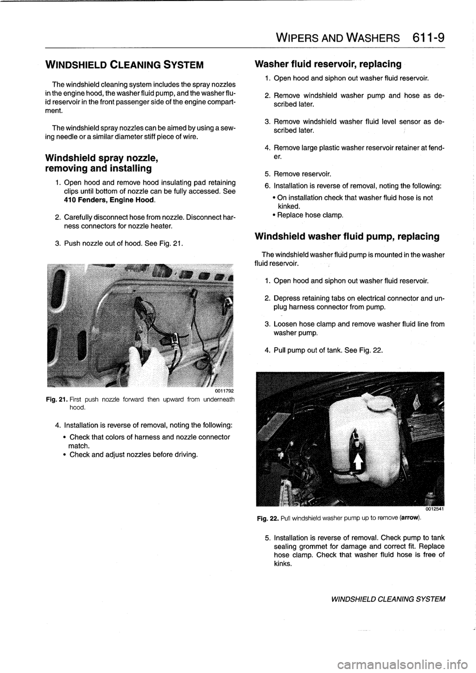
See
Fig
.
21
.
Fig
.
21
.
First
push
nozzle
forward
then
upward
from
underneath
hood
.
4
.
Installation
is
reverse
of
removal,
noting
the
following
:
"
Check
that
colors
of
harness
and
nozzle
connector
match
.
"
Check
and
adjust
nozzles
before
driving
.
WIPERSAND
WASHERS
611-
9
2
.
Remove
windshield
washer
pump
and
hose
as
de-
scribed
later
.
3
.
Remove
windshield
washer
fluid
level
sensor
as
de-
scribed
later
.
4
.
Remove
large
plastic
washer
reservoir
retainer
at
fend-
e
r
.
5
.
Remove
reservoir
.
6
.
Installation
is
reverse
of
removal,
noting
the
following
:
"
On
installation
check
that
washer
fluid
hose
is
not
kinked
.
"
Replacehose
clamp
.
Windshield
washer
fluid
pump,
replacing
The
windshield
washer
fluid
pump
ís
mounted
in
the
washer
fluid
reservoir
.
1
.
Open
hood
and
siphon
out
washer
fluid
reservoir
.
2
.
Depress
retaining
tabs
on
electrical
connector
and
un-
plug
harness
connector
from
pump
.
3
.
Loosen
hose
clamp
and
remove
washer
fluidline
from
washer
pump
.
4
.
PA
pump
out
of
tank
.
See
Fig
.
22
.
Fig
.
22
.
Pull
windshield
washer
pump
up
to
remove
(arrow)
.
5
.
Installation
is
reverse
of
removal
.
Check
pump
to
tank
sealing
grommet
for
damage
and
correct
fit
.
Replace
hose
clamp
.
Check
that
washer
fluid
hose
is
free
of
kinks
.
WINDSHIELD
CLEANING
SYSTEM
Page 428 of 759
611-
1
0
WIPERS
AND
WASHERS
Washer
fluidleve¡
sensor,
replacing
(modeis
with
check
control)
The
washer
fluid
level
sensor
is
mounted
in
the
fluid
reser-
voir,
near
the
bottom
of
thecontainer
.
NOTE-
Check
wire
leads
at
sensor
for
worn
insulation
and
cor-
rosion
.
Check
electrical
contacts
in
harness
connector
for
corrosion
.
1
.
Open
hood
and
siphon
out
washer
fluid
reservoir
.
2
.
Lift
harness
connector
retaining
lever
and
unplug
har-
ness
connector
to
washer
fluid
level
sensor
.
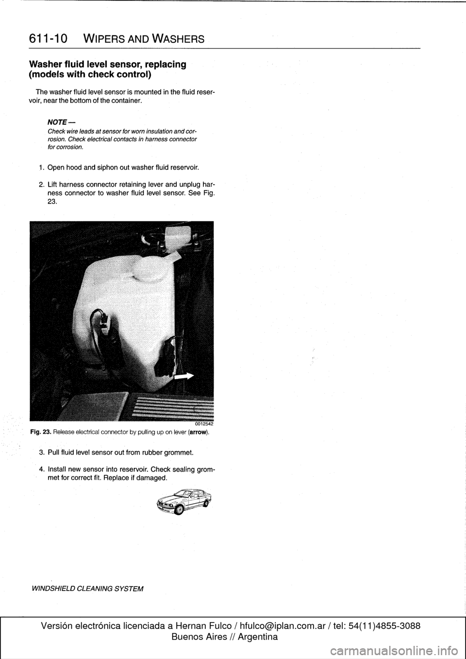
See
Fig
.
23
.
3
.
Pul¡
fluid
leve¡
sensor
out
from
rubber
grommet
.
4
.
Install
new
sensor
into
reservoir
.
Check
sealing
grom-
met
for
correct
fit
.
Replace
if
damaged
.
WINDSHIELD
CLEANING
SYSTEM
Page 439 of 759
3
.
Break
open
plastic
retainer
in
back
of
instrument
clus-
ter
andremove
coding
plug
.
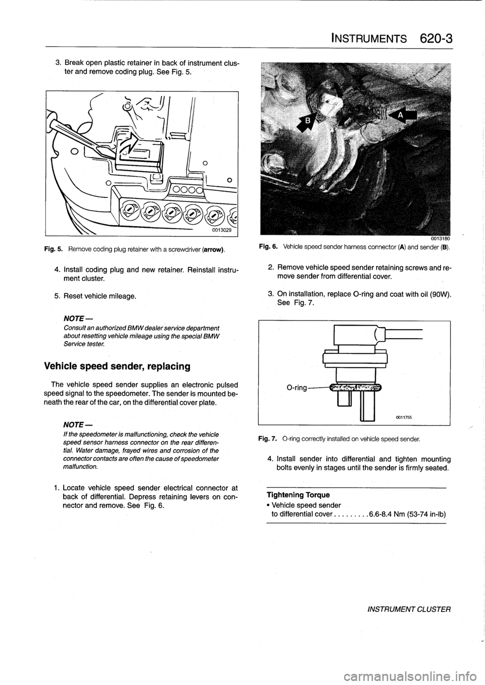
See
Fig
.
5
.
5
.
Reset
vehicle
mileage
.
1
ILO
NOTE-
Consultan
authorized
BMW
dealer
service
department
about
resetting
vehicle
mileage
using
the
special
BMW
Service
tester
.
Vehicle
speed
sender,
replacing
0
0013029
Fig
.
5
.
Remove
coding
plug
retainer
with
a
screwdriver
(arrow)
.
4
.
Install
coding
plug
and
new
retainer
.
Reinstall
instru-
ment
cluster
.
The
vehicle
speed
sender
supplies
an
electronic
pulsed
speed
signal
to
the
speedometer
.
The
sender
is
mounted
be-
neath
the
rear
of
the
car,
on
the
differential
cover
plate
.
1
.
Locate
vehicle
speed
sender
electrical
connector
at
back
of
differential
.
Depress
retaininglevers
on
con-
nector
and
remove
.
See
Fig
.
6
.
INSTRUMENTS
620-
3
0013180
Fig
.
6
.
Vehicle
speed
sender
harnessconnector
(A)
and
sender
(B)
.
2
.
Remove
vehicle
speed
sender
retaining
screws
and
re-
move
sender
from
differential
cover
.
3
.
On
installation,
replace
O-ring
and
coat
with
oil
(90W)
.
See
Fig
.
7
.
0011755
NOTE-
'
If
the
speedometer
is
malfunctioning,
check
the
vehicle
Fig
.
7,
O-ring
correctly
installed
on
vehicle
speed
sender,
speed
sensor
hamess
connectoron
the
rear
differen-
tial
.
Water
damage,
frayed
wires
and
corrosion
of
the
connectorcontactsareoftenthecause
ofspeedometer
4
.
Insta¡¡
sender
into
differential
and
tighten
mounting
malfunction
.
bolts
evenly
in
stages
until
the
sender
is
firmly
seated
.
Tightening
Torque
"
Vehicle
speed
sender
to
differential
cover
...
.
.....
6
.6-8
.4
Nm
(53-74
in-lb)
INSTRUMENT
CLUSTER
Page 450 of 759
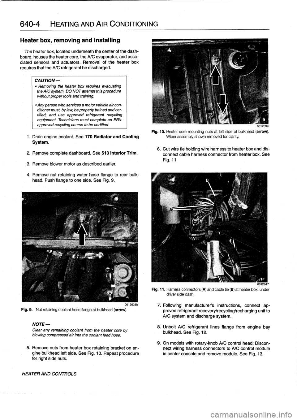
640-4
HEATING
AND
AIR
CONDITIONING
Heater
box,
removing
and
installing
The
heater
box,
located
underneath
thecenter
of
the
dash-
board,
houses
theheater
core,
the
A/C
evaporator,
and
asso-
ciated
sensors
and
actuators
.
Removal
of
theheater
box
requires
that
the
A/C
refrigerant
be
discharged
.
CAUTION-
"
Removing
the
heater
box
requires
evacuating
the
AIC
system
.
DO
NOT
attempt
this
procedure
without
proper
tools
and
training
.
"
Any
person
who
services
a
motor
vehicle
air
con-
ditioner
must,
by
law,
be
properly
trained
and
cer-
tified,
and
use
approved
refrigerant
recycling
equipment
.
Technicians
must
complete
an
EPA-
approved
recycling
course
to
be
certified
UU12639
Fig
.
10
.
Heater
core
mounting
nuts
at
left
sideof
bulkhead
(arrow)
.
1
.
Drain
engine
coolant
.
See
170
Radiator
and
Cooling
wiper
assembly
shown
removed
for
clarity
.
System
.
2
.
Remove
complete
dashboard
.
See513
Interior
Trim
.
3
.
Remove
blower
motoras
described
earlier
.
4
.
Remove
nut
retaining
water
hose
flange
to
rear
bulk-
head
.
I'ush
flange
to
one
side
.
See
Fig
.
9
.
Fig
.
9
.
Nut
retaining
coolant
hose
flangeat
bulkhead
(arrow)
.
NOTE-
Clear
any
remaining
coolant
from
the
heater
core
by
blowing
compressed
air
finto
the
coolant
feed
hose
.
HEATER
AND
CONTROLS
0012638b
6
.
Cut
wire
tie
holding
wire
harness
to
heater
box
and
dis-
connect
cable
harness
connector
from
heater
box
.
See
Fig
.
11
.
0012647
Fig
.
11
.
Harness
connectors
(A)
and
cable
tie
(B)
at
heaterbox,
under
driver
side
dash
.
7
.
Followingmanufacturer's
instructions,
connect
ap-
proved
refrigerant
recovery/recycling/recharging
unitto
A/C
system
and
discharge
system
.
8
.
Unbolt
A/C
refrigerantlines
flange
from
engine
bay
bulkhead
.
See
Fig
.
12
.
9
.
On
models
with
rotary-knob
A/C
control
head
:
Discon-
5
.
Remove
nuts
from
heater
box
retaining
bracket
on
en-
nect
wiring
harness
connectors
to
A/C
control
module
gine
bulkhead
left
side
.
See
Fig
.
10
.
Repeat
procedure
in
center
console
and
remove
module
.
See
Fig
.
13
.
for
right
side
nuts
.
Page 452 of 759
640-6
HEATING
AND
AIRCONDITIONING
Heater
core,replacing
1.
Drain
engíne
coolant
.
See170
Radiator
and
Cooling
System
.
WARNING
-
Allow
the
cooling
system
to
cool
before
opening
or
drainíng
the
cooling
system
.
2
.
Remove
center
console
.
See
513
Interior
Trim
.
3
.
Remove
Multi-Information
Display
(MID)
module
.
See
620
Instruments
.
4
.
Remove
lower
dash
panel
and
knee
bolster
on
driver
side
.
See
513
Interior
Trim
.
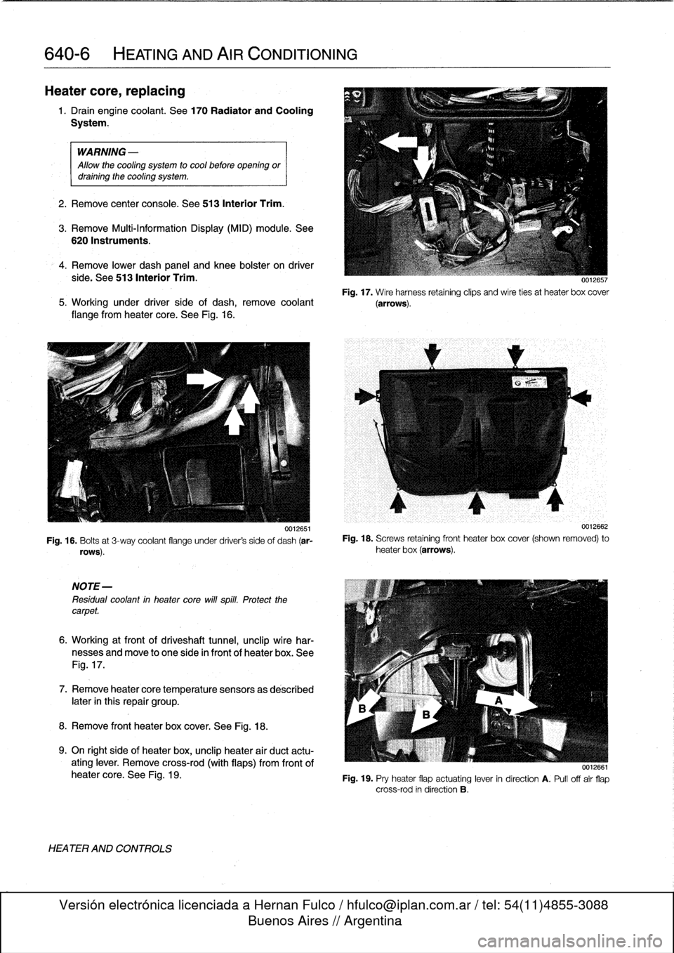
Fig
.
17
.
Wire
harness
retaining
clips
and
wire
ties
at
heater
box
cover
5
.
Working
under
driver
side
of
dash,
remove
coolant
(arrows)
.
flange
from
heater
core
.
See
Fig
.
16
.
0012651
Fig
.
16
.
Bolts
at
3-way
coolant
flange
under
driver's
side
of
dash
(ar-
rows)
.
NOTE-
Residual
coolant
in
heater
core
will
spill
.
Protect
thecarpet
.
6
.
Working
at
front
of
driveshaft
tunnel,
unclip
wire
har-
nesses
and
move
to
one
side
in
front
of
heater
box
.
See
Fig
.
17
.
7
.
Remove
heatercore
temperature
sensorsas
described
later
in
this
repair
group
.
8
.
Remove
front
heater
box
cover
.
See
Fig
.
18
.
9
.
On
right
side
of
heater
box,
unclip
heater
air
duct
actu-
ating
lever
.
Remove
cross-rod
(with
flaps)
from
frontof
heater
core
.
See
Fig
.
19
.
HEATER
AND
CONTROLS
0012662
Fig
.
18
.
Screws
retaining
front
heater
box
cover
(shown
removed)
to
heater
box
(arrows)
.
0012661
Fig
.
19
.
Pry
heater
flap
actuating
lever
in
direction
A
.
Pull
offair
flap
cross-rod
in
direction
B
.