Engine BMW 328i 1998 E36 Workshop Manual
[x] Cancel search | Manufacturer: BMW, Model Year: 1998, Model line: 328i, Model: BMW 328i 1998 E36Pages: 759
Page 234 of 759
240-
6
AUTOMATIC
TRANSMISSION
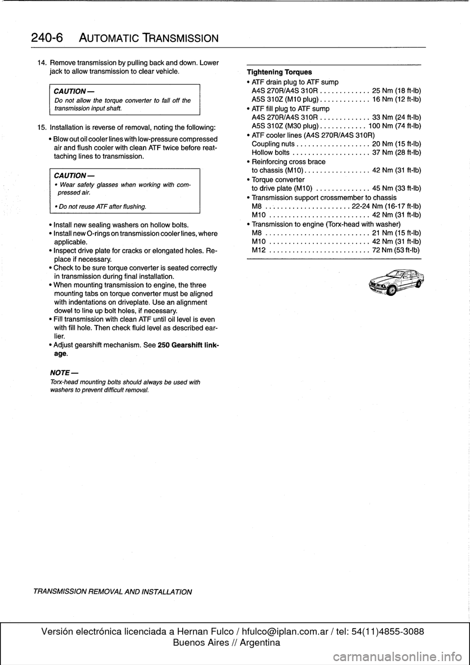
14
.
Remove
transmission
by
pulling
back
and
down
.
Lower
jack
to
allow
transmission
to
clear
vehicle
.
Tightening
Torques
"
ATF
drain
plug
to
ATF
sump
CA
UTION-
MS
270R/A4S
310R
....
..
....
.
..
25
Nm
(18
ft-Ib)
Do
not
allow
the
torque
converter
to
fati
off
the
ASS
310Z(M10
plug)
..
..
..
.
.
..
.
..
16
Nm
(12
ft-Ib)
transmission
inputshaft
.
"
ATF
fill
plug
to
ATF
sump
MS
270R/A4S
310R
..
..
....
..
..
.
33
Nm
(24
ft-Ib)
15
.
Installation
is
reverse
of
removal,
noting
the
following
:
MS
310Z(M30
plug)
......
.
.
..
.
.
100
Nm
(74
ft-Ib)
"Blowoutofcoolerlineswithlow-pressurecompressed
"
ATF
cooler
lines
(A4S
270R/A4S
310R)
air
and
flush
coolerwith
clean
ATF
twice
before
reat-
Coupling
nuts
............
.
.
..
..
.
20
Nm
(15
ft-Ib)
taching
lines
to
transmission
.
Hollow
bolts
.........
.
.....
..
..
.
37
Nm
(28
ft-Ib)
"
Reinforcing
cross
brace
CAUTION-
to
chassis
(M10)
.............
.
..
.
42
Nm
(31
ft-Ib)
"
Wear
safety
glasses
when
working
with
com-
"
Torque
converter
pressedair
.
to
driveplate
(M10)
.........
..
.
..
45
Nm
(33
ft-Ib)
"
Transmissionsupport
crossmember
to
chassis
"
Do
not
reuse
ATF
after
flushing
.
M8
......................
22-24
Nm
(16-17
ft-1b)
M10
................
.
....
..
.
..
42
Nm
(31
ft-Ib)
"
Install
new
sealing
washers
on
hollow
bolts
.
"
Transmissíon
to
engine
(Torx-head
with
washer)
"
Insta¡¡
new
O-rings
on
transmission
cooler
lines,
where
M8
......................
..
.
..
21
Nm
(15
ft-Ib)
applicable
.
M10
.....................
..
..
.
42
Nm
(31
ft-Ib)
"
Inspect
driveplate
for
cracks
or
elongatedholes
.
Re-
M12
................
.
....
..
.
..
72
Nm
(53ft-Ib)
place
if
necessary
.
"
Check
to
be
sure
torque
converter
is
seated
correctly
in
transmission
during
final
installation
.
"
When
mounting
transmission
to
engine,
the
three
mounting
tabs
on
torque
converter
must
be
aligned
with
indentations
on
driveplate
.
Use
an
alignment
dowel
to
line
up
bolt
holes,
if
necessary
.
"
Fill
transmission
with
clean
ATF
until
oil
leve¡
is
even
with
fill
hole
.
Then
check
fluid
leve¡
as
described
ear-
lier
.
"
Adjust
gearshift
mechanism
.
See
250
Gearshift
link-
age
.
NOTE-
Torx-head
mounting
bolts
shouldalwaysbe
used
with
washers
to
prevent
difficult
removal
.
TRANSMISSION
REMOVAL
AND
INSTALLATION
Page 236 of 759
250-2
GEARSHIFT
LINKAGE
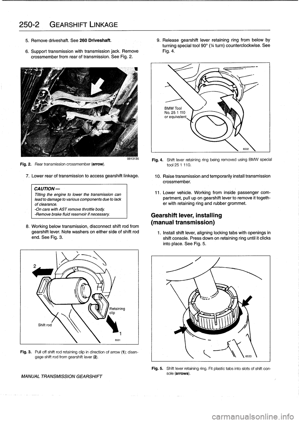
5
.
Remove
driveshaft
.
See260
Driveshaft
.
9
.
Release
gearshift
lever
retaining
ring
from
below
by
turningspecial
tool
90°(
1
/4
turn)
counterclockwise
.
See
6
.
Support
transmission
with
transmission
jack
.
Remove
Fig
.
4
.
crossmember
from
rear
of
transmission
.
See
Fig
.
2
.
Fig
.
2
.
Rear
transmission
crossmember
(arrow)
.
7
.
Lower
rear
of
transmission
to
access
gearshift
linkage
.
CAUTION-
Tilting
the
engine
to
lower
thetransmission
can
lead
to
damage
to
various
componente
due
to
lackof
clearance
.
-On
cars
with
AST
remove
throttle
body
.
-Remove
brake
fluid
reservoir
if
necessary
.
0013135
8
.
Working
below
transmission,
disconnect
shift
rod
from
gearshift
lever
.
Note
washers
on
either
side
of
shift
rod
end
.
See
Fig
.
3
.
v
clip
Shift
rod
Fig
.
3
.
Pull
off
shift
rod
retaining
clip
in
direction
of
arrow
(t)
;
disen-
gage
shift
rod
from
gearshift
lever
(2)
.
MANUAL
TRANSMISSION
GEARSHIFT
BMW
Tool
No
.
25
1
110
orequivalent
Fig
.
4
.
Shift
lever
retaining
ring
being
removed
using
BMW
special
tool
25
1
110
.
10
.
Raise
transmission
and
temporarily
instan
transmission
crossmember
.
11
.
Lower
vehicle
.
Working
from
inside
passengercom-
partment,
pull
upon
gearshift
lever
to
remove
it
togeth-
erwith
retaining
ring
and
rubber
grommet
.
Gearshift
lever,
installing
(manual
transmission)
6532
1
.
Instan
shift
lever,
aligninglocking
tabs
with
openings
in
shift
console
.
Press
down
on
retaining
ring
until
it
clicks
into
place
.
See
Fig
.
5
.
\
Retaining
Fig
.
5
.
Shift
lever
retaining
ring
.
Fit
plastic
tabs
into
slots
of
shift
con-
sole(arrows)
.
Page 237 of 759
2
.
Install
rubber
grommet
with
arrow
pointing
forward
.
In-
AUTOMATic
TRANSMISSION
stall
shift
rod
and
shift
boot
.
GEARSHIFT
NOTE-
Install
rubbergrommet
correctly
so
that
is
seals
outwa-
ter
.
4
.
Install
driveshaft
and
heat
shield
.
See
260
Driveshaft
.
Manual
valveleven
(at
transmission)
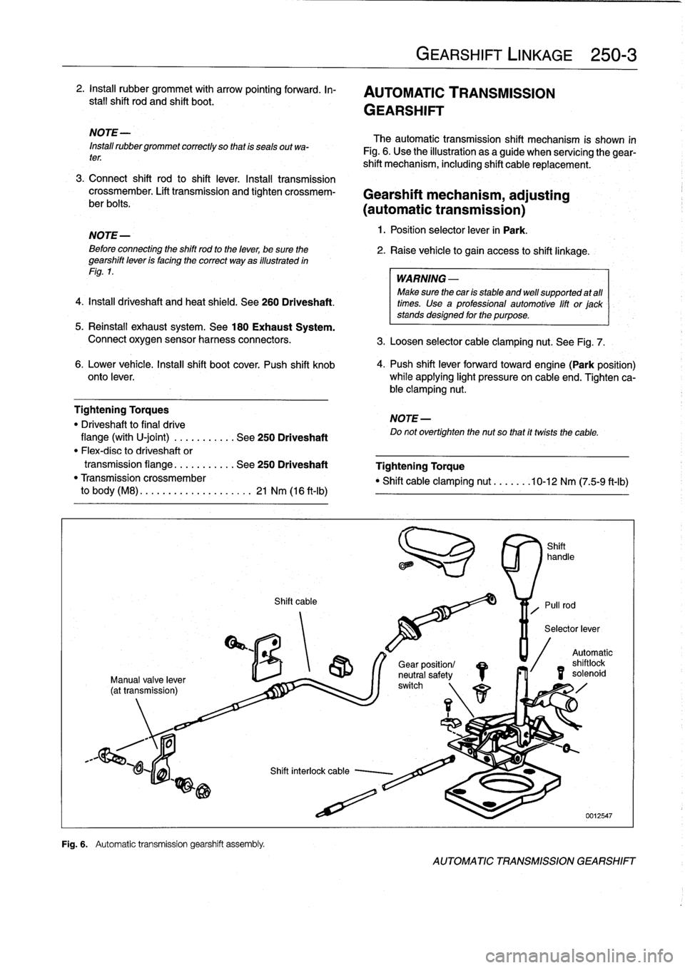
Fig
.
6
.
Automatic
transmission
gearshift
assembfy
.
Shift
cable
GEARSHIFT
LINKAGE
250-
3
The
automatic
transmission
shift
mechanism
is
shown
in
Fig
.
6
.
Use
the
illustration
as
a
guide
when
servícing
the
gear-
shift
mechanism,
including
shift
cable
replacement
.
3
.
Connect
shift
rod
to
shift
lever
.
Install
transmission
crossmember
.
Lift
transmission
and
tighten
crossmem-
Gearshift
mechanism,
adjusting
ber
bolts
.
(automatictransmission)
NOTE-
1
.
Position
selector
lever
in
Park
.
Beforeconnecting
the
shift
rod
to
the
lever,
be
sure
the
2
.
Raise
vehicle
to
gain
access
to
shift
linkage
.
gearshift
leven
is
facing
the
correct
way
as
illustrated
in
Fig
.
1
.
WARNING
-
Make
sure
thecan
is
stable
and
well
supported
at
all
times
.
Use
a
professional
automotive
lift
or
jack
stands
designed
for
the
purpose
.
5
.
Reinstall
exhaust
system
.
See
180
Exhaust
System
.
Connect
oxygen
sensor
harness
connectors
.
3
.
Loosen
selector
cable
clamping
nut
.
See
Fig
.
7
.
6
.
Lower
vehicle
.
Insta¡¡
shift
boot
cover
.
Push
shift
knob
4
.
Push
shift
lever
forwardtoward
engine(Park
position)
onto
lever
.
while
applying
light
pressure
on
cable
end
.
Tighten
ca-
ble
clamping
nut
.
Tightening
Torques
NOTE-
"
Driveshaft
to
final
drive
Do
not
overtighten
the
nut
so
that
it
twists
the
cable
.
flange
(with
U-joint)
.
..
.
.....
.
.
See
250
Driveshaft
"
Flex-disc
to
driveshaft
or
transmission
flange
...
.
.......
See
250
Driveshaft
Tightening
Torque
"
Transmission
crossmember
"
Shift
cable
clamping
nut
.......
10-12
Nm
(75-9
ft-Ib)
to
body
(M8)
.
.
.
...
..............
21
Nm
(16
ft-Ib)
/S
r\
1
1
Gear
position/
neutral
safetyswitch
Automatic
shilo
solenoid
id
AUTOMATIC
TRANSMISSION
GEARSHIFT
Page 239 of 759
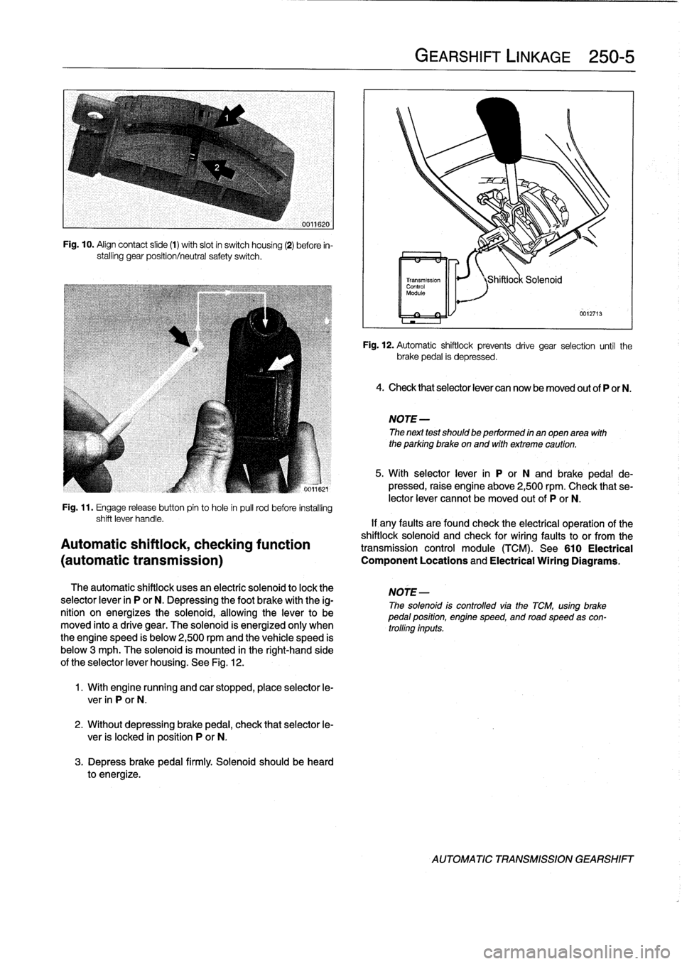
Fig
.
10
.
Align
contact
slide
(1)
with
slot
in
switch
housing
(2)
before
in-
stalling
gear
position/neutral
safety
switch
.
Fig
.
11
.
Engage
release
button
pin
to
hole
in
pull
rod
before
installing
The
automatic
shiftlock
uses
an
electríc
solenoid
to
lock
the
selector
lever
in
P
or
N
.
Depressing
the
foot
brake
withthe
ig-
nition
on
energizes
the
solenoid,
allowingthe
lever
to
be
moved
into
a
drive
gear
.
The
solenoid
is
energized
only
when
the
engine
speed
is
below
2,500
rpmand
thevehicle
speed
is
below
3
mph
.
The
solenoid
ís
mounted
in
the
right-hand
side
of
theselector
lever
housing
.
See
Fig
.
12
.
1
.
With
engine
running
and
car
stopped,
place
selector
le-
ver
in
P
or
N
.
2
.
Without
depressing
brake
pedal,
check
that
selector
le-
ver
is
locked
in
position
P
or
N
.
3
.
Depress
brakepedal
firmly
.
Solenoid
should
be
heard
to
energize
.
GEARSHIFT
LINKAGE
250-
5
Fig
.
12
.
Automatic
shiftlock
prevents
drive
gear
selection
until
the
brakepedal
is
depressed
.
4
.
Check
thatselector
lever
can
now
be
moved
out
of
P
or
N
.
NOTE
-
The
next
test
should
be
performed
in
anopen
area
with
the
parking
brake
on
and
with
extreme
caution
.
5
.
With
selector
lever
in
P
or
N
and
brake
pedal
de-
pressed,
raise
engine
above
2,500
rpm
.
Check
that
se-
lector
lever
cannotbe
moved
outof
P
or
N
.
shift
lever
handle
.
If
any
faults
are
found
check
the
electrical
operation
of
the
shiftlock
solenoid
and
check
for
wiring
faultsto
or
from
the
Automatic
shiftiock,
checking
function
transmission
control
module(TCM)
.
See610
Electrical
(automatic
transmission)
Component
Locations
and
Electrical
Wiring
Diagrams
.
NOTE
-
The
solenoid
is
controlled
viathe
TCM,
using
brakepedal
position,
engine
speed,
and
road
speed
as
con-
trolling
inputs
.
AUTOMATIC
TRANSMISSION
GEARSHIFT
Page 241 of 759
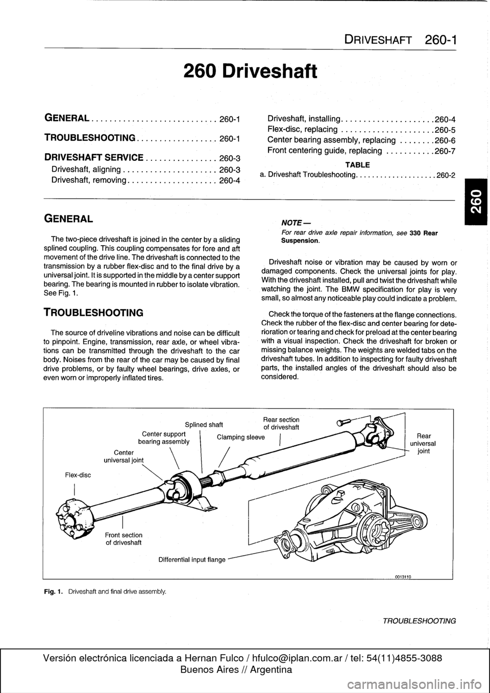
DRIVESHAFT
SERVICE
.
...
.
.
.
...
.
..
.
.
.260-3
Driveshaft,
aligning
...............
.
...
.
.
260-3
Driveshaft,
removing
..............
.
.
.
.
.
.
260-4
260
Driveshaft
DRIVESHAFT
260-1
GENERAL
.
.
.
.
.
.
.
.....
.
.
.
........
.
...
.
260-1
Driveshaft,
installing
.
....
.
..
.
............
260-4
Flex-disc,
replacing
.....
.
.
.
.............
260-5
TROUBLESHOOTING
..
.
.
.
...
.
.........
260-1
Center
bearing
assembly,
replacing
.
......
.260-6
Frontcentering
guide,
replacing
..
.
.......
.
260-7
TABLE
a
.
Driveshaft
Troubleshooting
.
.
...
......
.
....
..
.
.
260-2
GENERAL
NOTE-
For
rear
drive
axlerepair
information,
see330
Rear
The
two-piece
driveshaft
is
joined
in
thecenter
by
a
sliding
Suspension
.
splined
coupling
.
This
coupling
compensates
for
fore
and
aft
movement
of
the
drive
line
.
The
driveshaft
ís
connected
to
the
Driveshaft
noise
or
vibration
may
be
caused
by
worn
or
transmission
bya
rubber
flex-disc
and
to
the
final
drive
by
a
damaged
components
.
Check
the
universal
joints
for
play
.
universal
joint
.
It
is
supported
in
the
micidle
by
a
center
support
With
the
driveshaft
installed,
pull
and
twist
the
driveshaft
while
bearing
.
The
bearing
is
mounted
in
rubber
to
isolate
vibration
.
watching
the
joint
.
The
BMW
specificationfor
play
is
very
See
Fig
.
1
.
small,
so
almost
any
noticeableplay
could
indicate
a
problem
.
TROU
BLESHOOTING
Check
thetorque
of
thefasteners
at
the
flange
connections
.
Check
therubber
of
the
flex-disc
and
center
bearing
for
dete
The
source
of
driveline
vibrations
and
noise
can
be
difficult
rioration
or
tearíng
and
check
for
preload
at
the
center
bearing
to
pinpoint
.
Engine,
transmission,
rear
axle,
or
wheel
vibra-
with
a
visual
inspection
.
Check
the
driveshaft
for
broken
or
tions
can
be
transmitted
through
the
driveshaft
to
the
car
missing
balance
weights
.
The
weights
are
welded
tabs
on
the
body
.
Noises
from
the
rear
of
thecar
may
be
caused
by
final
driveshaft
tubes
.
In
addition
to
inspecting
for
faulty
driveshaft
drive
problems,
orby
faulty
wheel
bearings,
drive
axies,
or
parts,
the
installed
angles
of
the
driveshaft
should
also
be
evenworn
or
improperly
inflatedtires
.
considered
.
Flex-disc
Center
universal
joint
Fig
.1
.
Driveshaft
and
final
drive
assembly
.
Rear
section
Splined
shaft
of
driveshaft
Center
support
`
Clamping
sleeve
bearíng
assembly
Differential
inputflange
0013110
TROUBLESHOOTING
Page 242 of 759
260-2
DRIVESHAFT
Further
inspection
requires
removal
of
the
driveshaft
.
Check
the
front
centering
guide
on
the
transmission
output
flange
for
damage
or
misalignment
.
Also
check
runoutatthe
transmission
outputflange
and
output
shaft,
and
at
the
final
drive
input
flange
.
Check
the
bolt
hole
bores
in
theflange
for
wear
and
elongation
.
Driveshaftflange
runout
(max
.
allowable)
"
Transmission
outputflange
axial
play
...
.
..
...
..
.
.......
0
.10
mm
(0
.004
in
.)
radial
play
.......
...
.
.
.......
0
.07
mm
(0
.003
in
.)
"
Final
driveinput
flange
radial
play
(measured
at
driveshaft
centering
lip)
..
......
0
.07
mm
(0
.003
in
.)
Spinthe
center
bearing
and
check
for
the
smooth
operation
without
play
.
Check
that
thesplines
of
the
sliding
coupling
move
freely
.
Clean
and
lubricate
the
splines
with
molybdenum
disulfide
grease
(Molykote
®
Longterm
2
or
equivalent)
.
Check
the
universal
joints
for
wear
or
binding
.
If
any
joint
isdif-
ficult
to
move
or
binds,
the
driveshaft
section
should
be
replaced
.
Table
a
.
Driveshaft
Troubleshooting
NOTE-
With
the
driveshaft
installed,
theactual
amount
that
the
universal
joints
pivot
is
limited
.
For
the
most
accurate
test,
check
universal
joints
in
their
normal
range
of
movement
.
If
inspection
revealsnothing
wrong
with
the
driveshaft,
it
may
need
to
be
rebalanced
.
This
can
be
done
by
a
speciality
driveshaft
repair
shop
.
Also,
check
the
alignment
ofthe
drive-
shaft
as
described
below
.
NOTE-
Minor
driveshaftvibrations
can
often
be
correctedsim-
ply
by
disconnecting
the
driveshaftat
the
finaldrive,
and
repositíoning
the
driveshaft
90°,
180°
or270°
inre-
lationto
the
final
drive
input
flange
.
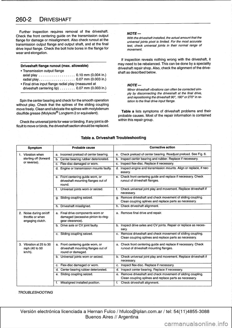
Table
a
lists
symptoms
of
driveshaft
problems
and
their
probable
causes
.
Most
of
the
repair
information
is
contained
within
this
repair
group
.
Symptom
Probable
cause
Corrective
action
1
.
Vibration
when
a
.
Incorrect
preload
of
center
bearing
.
a
.
Check
preload
of
center
bearing
.
Readjust
preload
.
See
Fig
.
6
.
starting
off
(forward
b
.
Center
bearing
rubber
deteriorated
.
b
.
Inspect
center
bearing
and
rubber
.
Replace
if
necessary
.
orreverse)
.
c
.
Flex-disc
damaged
or
worn
.
c
.
Inspect
flex-disc
.
Replace
if
necessary
.
TROUBLESHOOTING
d
.
Engine
or
transmission
mounts
faulty
.
I
d
.
Inspect
engine
and
transmission
mounts
.
Align
or
replace,
if
nec-
essary
.
e
.
Front
centering
guide
worn,
or
e
.
Check
front
centering
guide
and
replace
if
necessary
.
Check
driveshaft
mounting
flanges
out
of
runout
of
driveshaft
flanges
.
round
.
f
.
Universal
joints
worn
or
seized
.
f
.
Check
universal
joint
play
and
movement
.
Replace
driveshaft
if
necessary
.
g
.
Sliding
coupling
seized
.
g
.
Remove
driveshaft
and
check
movement
of
sliding
coupling
.
Clean
coupling
splines
and
replace
parts
asnecessary
.
h
.
Driveshaft
misaligned
.
h
.
Check
driveshaft
alignment
.
2
.
Noise
during
on/off
a
.
Finaldrive
components
worn
or
a
.
Remove
final
drive
and
repair
.
throttle
or
when
damaged
(excessive
pinion-to-ring-
engagíng
clutch
.
gear
clearance)
.
b
.
Drive
axleor
CV
joint
faulty
.
b
.
Inspect
drive
axles
and
CV
joints
.
Repair
or
replace
as
neces-
sary
.
c
.
Sliding
coupling
seized
.
c
.
Remove
driveshaft
and
check
movement
of
sliding
coupling
.
Clean
coupling
splines
and
replace
parts
as
necessary
.
3
.
Vibration
at
25
to
30
a
.
Front
centering
guideworn,
or
a
.
Check
front
centering
guide
and
replace
if
necessary
.
Check
mph
(40
to
50
driveshaft
mounting
flanges
out
of
runout
of
driveshaft
mounting
flanges
.
km/h
).
round
or
damaged
.
b
.
Universal
joints
worn
or
seized
.
b
.
Check
universal
joint
play
and
movement
.
Replace
driveshaft
if
necessary
.
c
.
Flex-disc
damaged
or
worn
.
c
.
Inspect
flex-disc
.
Replace
if
necessary
.
d
.
Center
bearing
rubber
deteriorated
.
d
.
Inspect
center
bearing
.
Replace
if
necessary
.
e
.
Sliding
coupling
seized
.
e
.
Remove
driveshaft
and
check
movement
of
sliding
coupling
.
Clean
coupling
splines
and
replace
parts
asnecessary
.
f
.
Misaligned
installed
position
.
f
.
Check
driveshaft
alignment
.
Page 243 of 759
Symptom
1
Probable
cause
4
.
Vibration,
audible
a
.
Front
centering
guide
worn,
or
a
.
Check
front
centering
guide
and
replace
if
necessary
.
Check
rumble
over35
mph
driveshaft
mounting
flanges
out
of
runout
of
driveshaft
mounting
flanges
.
(60
km/h)
.
round
or
damaged
.
b
.
Mounting
flange
bolts
loose
or
holes
b
.
Remove
driveshaft
and
check
transmissionoutput
flange
and
worn
.
final
drive
input
flange
.
Replace
if
necessary
.
c
.
Driveshaft
unbalanced
.
c
.
Check
driveshaft
for
loose
or
missing
balance
weights
.
Have
driveshaft
rebalanced
or
replace
if
necessary
.
DRIVESHAFT
SERVICE
Driveshaft,
aligning
d
.
Universal
joints
worn
or
seized
.
d
.
Check
universal
joint
play
and
movement
.
Replace
driveshaft
if
necessary
.
e
.
Sliding
coupling
seized
.
e
.
Remove
driveshaft
and
check
movement
of
sliding
coupling
.
1
Clean
coupling
splines
or
replace
parts
asnecessary
.
f
.
Incorrect
preload
of
center
bearing
.
f
.
Check
preload
of
center
bearing
.
Readjust
if
necessary
.
g
.
Center
bearing
faulty
.
g
.
Replace
center
bearing
.
h
.
Final
drive
rubber
mount
faulty
h
.
Inspect
final
drive
rubber
mount
and
replace
if
necessary
.i.
Driveshaft
misaligned
.
i.
Check
driveshaft
alignment
.
Repair
kits
for
the
universal
joints
are
not
available,
and
it
is
not
common
practice
to
repair
the
universal
joints
on
BMW
driveshafts
.
Worn
or
damaged
universal
joints
usually
require
replacement
of
that
section
of
the
driveshaft
.
The
driveshaft
is
balanced
to
cose
tolerances
.
Whenever
it
is
to
be
removed
or
disassembied,
the
mounting
flanges
and
driveshaft
sections
should
bemarked
with
paint
or
a
punch
before
proceeding
with
work
.
This
will
ensure
that
the
drive-
shaft
can
be
reassembled
or
installed
in
exactlythe
same
ori-
entation
.
Universal
joint
play
"
Maximum
allowable
...........
0.15
mm
(0.006
in
.)
The
alignment
of
the
driveshaft
does
not
normally
need
to
be
checked
unless
the
engine/transmission
orthe
final
drive
havebeen
removed
and
installed
.
If,
however,
all
other
parts
of
the
driveshaft
havebeen
inspected
and
found
to
be
okay,
butthere
is
still
noise
or
vibration,
driveshaft
alignment
should
be
checked
.
There
aretwo
important
driveshaft
alignment
checks
.
The
first
is
to
make
sure
that
the
driveshaft
runs
straight
from
the
transmission
to
the
final
drive
;
without
any
variation
from
side-
to-side
caused
by
misalignment
ofthe
engine/transmission
in
its
mounts
.
Make
a
basic
check
by
sighting
along
the
drive-
shaft
from
back
lo
front
.
Any
misalignmentshould
be
apparent
from
the
center
bearingforward
.
To
adjustthe
side-to-side
alignment,
loosen
the
transmission
or
engine
mounts
to
repo-
sition
them,
then
retighten
the
mounts
:
The
driveshaft
should
be
exactly
centered
in
the
driveshaft
tunnel
.
See
Fig
.
2
.
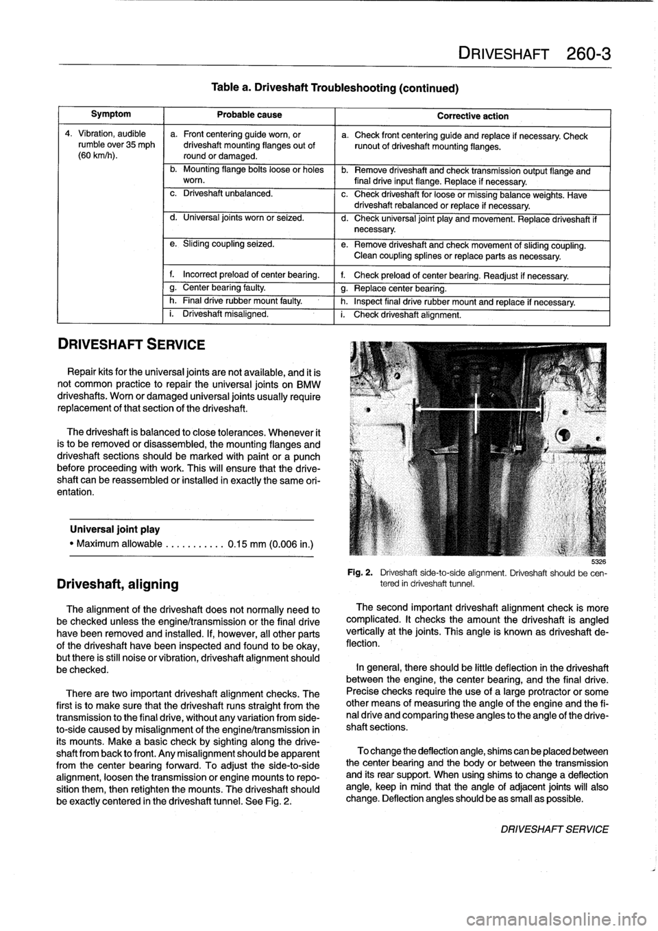
Table
a
.
Driveshaft
Troubleshooting
(continued)
DRIVESHAFT
260-3
Corrective
action
b
:izó
Fig
.
2
.
Driveshaft
side-to-side
alignment
.
Driveshaft
should
be
cen-
tered
in
driveshaft
tunnel
.
The
second
important
driveshaft
alignment
check
is
more
complicated
.
It
checks
the
amount
the
driveshaft
is
angled
vertically
at
the
joints
.
This
angle
is
known
as
driveshaft
de-
flection
.
In
general,
there
should
be
little
deflection
in
the
driveshaft
between
the
engine,
thecenter
bearing,
and
the
final
drive
.
Precise
checks
require
theuse
of
a
large
protractor
or
some
other
means
of
measuring
the
angle
of
the
engine
and
the
fi-
nal
drive
and
comparing
these
angles
to
the
angle
of
the
drive-
shaft
sections
.
To
change
the
deflection
angle,
shims
can
be
placed
between
the
center
bearing
and
the
body
or
between
the
transmission
and
íts
rear
support
.
When
using
shims
to
change
a
deflection
angle,
keep
in
mind
that
the
angle
of
adjacent
joints
will
also
change
.
Deflection
anglesshould
beas
small
as
possible
.
DRIVESHAFTSERVICE
Page 250 of 759
300-2
SUSPENSION,
STEERING
AND
BRAKES-GENERAL
Steering
INTEGRATED
SYSTEMS
The
steering
linkage
connects
the
rack-and-pinion
unit
through
tie
rodsto
the
steering
arms
.
The
tie
rod
ends
allow
the
wheels
to
pivot
and
react
to
suspension
travel
.
Rear
Suspension
The
rear
axle
carrier
is
the
main
mounting
point
for
the
final
drive
housing
and
the
rear
suspension
components
.
Trailing
arms
locatethe
rear
wheels
and
anchorthe
springs,
shocks
and
stabilizer
bar
.
Driveaxies
with
constant-velocity
(CV)
joints
at
both
ends
transfer
power
from
the
differential
to
the
road
wheels
.
The
differential
is
mounted
to
the
rearaxle
carrier
through
rubber
mountsand
bushings
to
hele
isolate
drivetrain
noise
and
vibration
.
Brakes
E36
cars
areequipped
with
power
disc
brakes
with
an
inte-
gral
antilock
brakes
(ABS)
.
The
parking
brake
is
a
dual-drum
system
integrated
with
the
rear
brake
rotors
.
See
Fig
.
3
.
Power
assist
is
provided
by
a
vacuum
booster
when
the
en-
gine
is
running
.
The
brakepedal
pushrod
is
connected
directly
to
the
master
cylinder,
so
failure
of
the
vacuum
booster
does
not
normally
result
in
total
brake
failure
.
0012124
Each
disc
brakeuses
a
caliper
with
a
single
hydraulic
cylin-
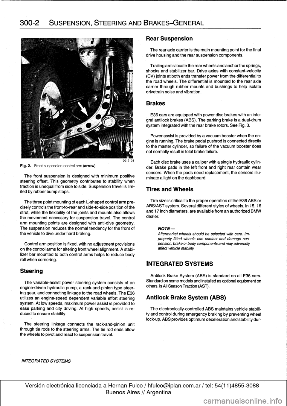
Fig
.
2
.
Front
suspension
control
arm
(arrow)
.
der
.
Brake
pads
in
the
left
front
and
right
rear
contain
wear
sensors
.
When
the
padsneed
replacement,the
sensors
illu-
The
front
suspension
is
designed
with
minimum
positive
minate
a
light
on
the
dashboard
.
steering
offset
.
This
geometry
contributes
to
stability
when
traction
is
unequalfrom
side
to
side
.
Suspension
travel
is
lim-
Tires
and
Wheels
ited
by
rubber
bump
stops
.
The
three
point
mounting
of
each
L-shaped
control
arm
ere-
Tiresize
is
critica¡
to
the
proper
operatíon
of
the
E36
ABS
or
cisely
controls
the
front-to-rear
and
side-to-side
position
of
the
ABS/AST
system
.
Severa¡
different
styles
of
wheels,
in
15,16
strut,
while
the
flexibility
of
the
joints
and
mounts
alsoallows
and
17
inch
diameters,
are
available
from
an
authorized
BMW
the
movement
necessary
for
suspension
travel
.
The
control
dealer
.
arm
mounting
points
are
designed
with
anti-dive
geometry
.
The
suspension
reduces
the
normaltendency
for
the
front
of
NOTE-
the
vehicle
to
dive
under
hard
braking
.
Aftermarket
wheelsshould
be
selected
wlth
care
.
Im-
properly
fitted
wheels
can
contact
anddamage
sus
Control
arm
position
is
fixed,
with
no
adjustment
provisions
pension,
brakeorbodycomponentsandmayadversely
on
the
control
arms
for
alter¡ng
front
wheel
al
ignment
.
A
stabi-
affect
vehicle
stability
.
lizer
bar
mounted
to
both
control
arms
heles
to
reduce
body
rol¡
whencomering
.
INTEGRATED
SYSTEMS
Antilock
Brake
System
(ABS)
is
standard
on
all
E36
cars
.
The
variable-assist
power
steering
system
consists
of
an
Standard
on
some
models
and
installed
as
optional
equipment
on
engine-driven
hydraulic
pump,
a
rack-and-pinion
type
steer-
others,
is
All
Season
Traction
(AST)
.
ing
gear,
and
connecting
linkage
to
the
road
wheels
.
TheE36
utilizes
an
engine-speed
dependent
variable
effort
steering
Antilock
Brake
System
(ABS)
system
.
At
low
speeds,
maximum
power
assist
is
provided
to
ease
parking
and
city
driving
.
Athigh
speeds,
assist
is
re-
The
electronically-controlled
ABS
maintains
vehícle
stabili
duced
to
ensure
stability
.
ty
and
control
during
emergency
braking
by
preventing
wheel
lock-up
.
ABS
provides
optimum
deceleration
and
stability
dur-
Page 252 of 759
300-4
SUSPENSION,
STEERING
AND
BRAKES-GENERAL
Three-channel
ABS
ís
used
on
al[
E36
cars
equipped
with
Al¡
Season
Traction
(AST)
standard
ABS
.
Each
front
wheelhas
a
separate
solenoid
valve
to
modulate
hydraulic
pressure
to
that
brake
caliper
.
The
traction
control
system
works
in
conjunction
with
ABS
The
rear
wheels
are
modulated
asa
pair,
controlled
by
a
sin-
and
the
engine
management
system
to
enhance
vehicle
con
gle
solenoid
valve
.
trol
.
The
main
function
of
the
AST
system
is
to
maintain
the
rolling
contact
between
the
tires
and
the
road
surface
under
al¡
driving
E36
cars
equipped
with
ABS/AST
utilize
a
four
channel
sys-
conditions
.
This
is
achieved
through
exact
application
and
tem,
which
functionsexactly
as
the
three
channelsystem
management
of
braking
and
drivetrain
forces
.
above,except
that
the
rear
wheels
are
modulated
individually
.
IDLE
SPEED
CONTROL
VALVE
HROTTLE
PLATE
6
.
Í
III
i
ADS
ACTU
AT
OR
THROTTLE
PLATE
POSITION
SENSOR
DME
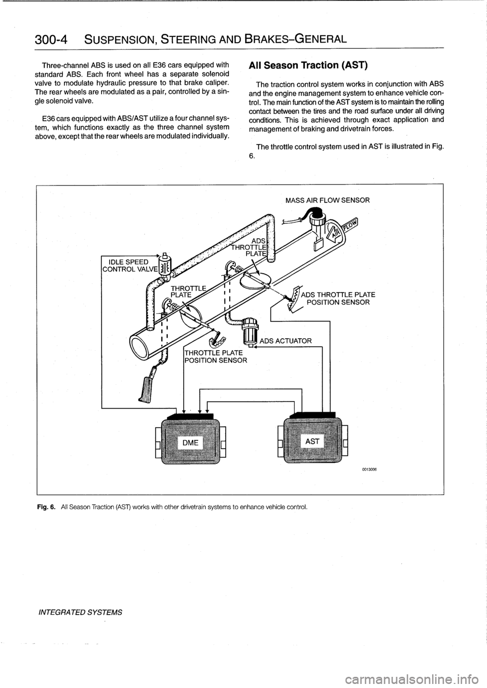
Fig
.
6
.
All
Season
Traction
(AS)
works
withother
drivetrain
systems
to
enhance
vehicle
control
.
INTEGRATED
SYSTEMS
The
throttle
control
system
used
in
AST
is
illustrated
in
Fig
.
MASS
AIR
FLOW
SENSOR
JADS
THROTTLE
PLATE
POSITION
SENSOR
0013006
Page 253 of 759
NOTE-
The
traction
control
system
referred
to
as
AST
(all
sea-
son
traction)
may
also
be
referred
to
as
ASC
(Automat-
ic
Stability
Control)
and
ASC+T
(Automatic
Stability
Control+Traction)
.
The
AST
system
improves
traction
by
electronically
apply-
ing
the
rear
brakes
when
therear
drive
wheels
are
spinning
at
a
faster
rate
than
the
front
wheels
.
The
combined
ABS/AST
control
module,
operating
through
the
ABS
hydraulic
control
unit,
modulates
braking
force
at
therear
wheels
.
In
addition,
AST
uses
retarded
ignition
timing
and
an
auxil-iary
engine
throttle
plate
to
reduceengine
torque
and
maintain
vehicle
stability
.
The
auxiliary
throttle
plate
is
held
open
by
spring
pressure
.
The
AST
system
actívates
the
auxiliary
throttie
position
motor
(ADS)
to
cose
the
AST
throttle
as
needed
.
This
reduces
the
volume
of
engine
intake
air
.
Due
to
the
throttle
closing
very
rapidly
during
AST
operationthe
driver
cannot
increase
theengine
power
output
regardless
of
how
far
theaccelerator
pedal
is
pushed
to
the
floor
.
The
auxiliary
throttle
plate
is
placed
ahead
of
the
conven-
tional
throttle
plate
in
the
throttle
body
.
Traction
control
also
comes
into
operationduringdecelera-
tion
.
Decelerating
on
snowy
or
icy
road
surfaces
can
lead
to
rear
wheel
slip
.
If
a
rear
wheel
startsto
drag
or
lock
up
when
the
throttle
is
closed
rapidly
orduringdownshifting,the
AST
system
can
limit
the
problem
by
advancing
the
ignition
timing
.
A
switch
on
the
center
console
is
used
to
togglethe
AST
on
or
off
.
The
AST
system
is
designed
to
be
maintenance
free
.
There
are
no
adjustments
that
can
be
made
.
Repair
and
trouble-
shooting
of
the
AST
system
requires
special
test
equipment
andknowledgeand
should
be
performed
only
by
an
autho-
rized
BMW
dealer
.
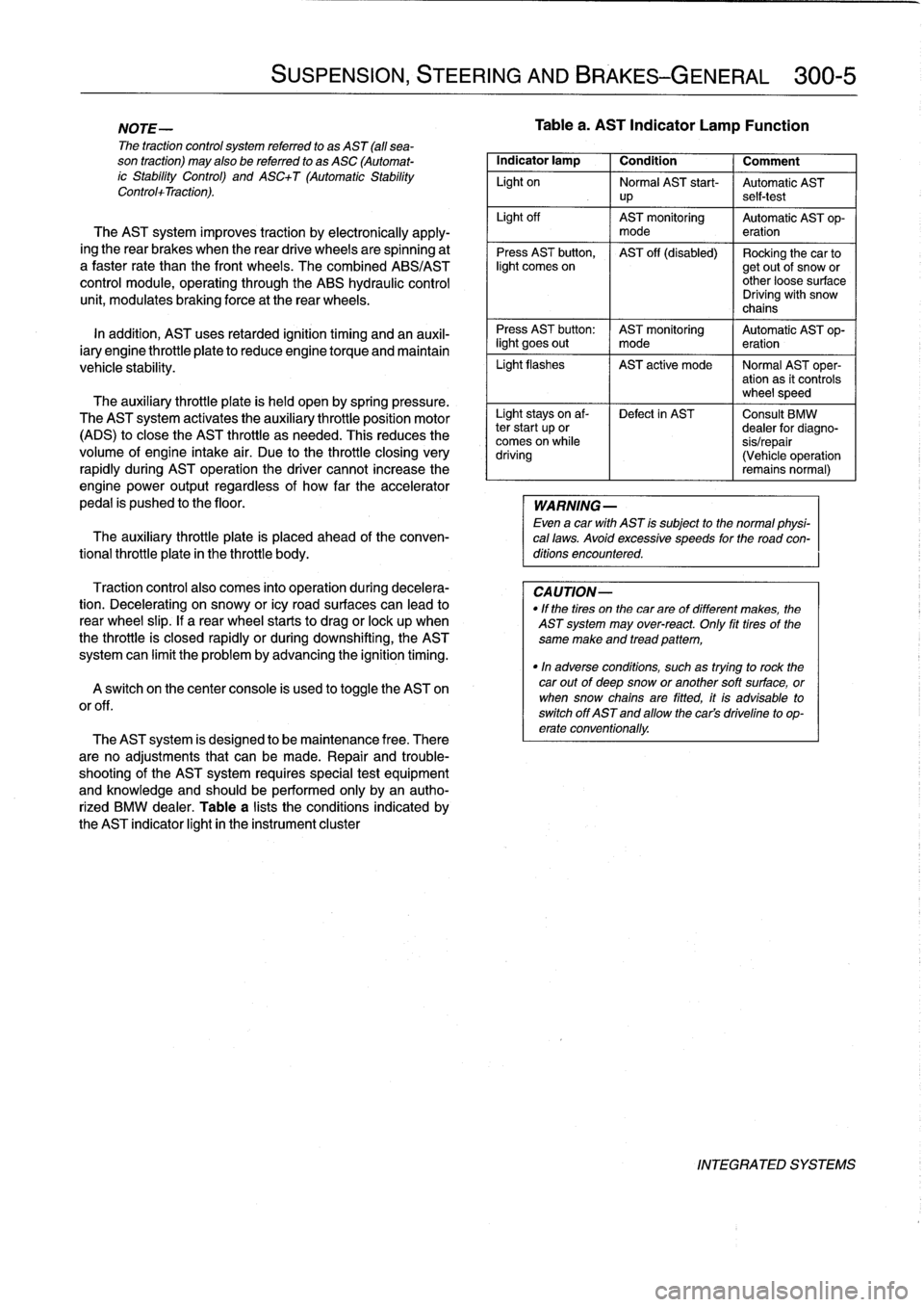
Table
a
lists
theconditions
indicated
by
the
AST
indicator
light
in
the
instrument
cluster
SUSPENSION,
STEERING
AND
BRAKES-GENERAL
300-5
Tablea
.
AST
Indicator
Lamp
Function
Indicator
lamp
1
Condition
1
Comment
Light
on
Normal
AST
start-
Automatic
AST
up
self-test
Light
off
AST
monitoring
Automatic
AST
op-
mode
eration
Press
AST
button,
AST
off
(disabled)
Rocking
the
car
tolight
comes
on
getout
of
snow
or
other
loose
surface
Driving
with
snow
chains
Press
AST
button
:
AST
monitoring
Automatic
AST
op-
light
goes
out
I
mode
eration
Light
flashes
AST
active
mode
I
Normal
AST
oper-
ation
as
it
controls
wheel
speed
Light
stays
on
af-
Defect
in
AST
Consult
BMW
ter
start
up
or
dealer
for
diagno-
comes
on
while
sis/repair
driving
(Vehicle
operation
remains
normal)
WARNING
-
Even
a
car
with
AST
is
subject
to
the
normal
physi-
cal
laws
.
Avoid
excessive
speeds
for
the
road
con-
ditions
encountered
.
CAUTION-
"
If
the
tires
on
the
carare
of
different
makes,
the
AST
system
may
over-react
.
Only
fit
tires
of
the
same
make
and
tread
pattem,
"In
adverse
conditions,
such
as
trying
to
rock
the
car
outof
deep
snow
or
another
soft
surface,
or
when
snow
chainsare
fitted,
it
is
advisable
to
switch
off
AST
and
allow
the
cars
driveline
to
op-
erate
conventionally
.
INTEGRATED
SYSTEMS