check BMW 428I XDRIVE COUPE 2016 Owners Manual
[x] Cancel search | Manufacturer: BMW, Model Year: 2016, Model line: 428I XDRIVE COUPE, Model: BMW 428I XDRIVE COUPE 2016Pages: 247, PDF Size: 5.26 MB
Page 5 of 247
Addendum
ADDENDUM TO OWNER'S MANUAL
We wanted to provide you with some updates
and clarifications with respect to the printed
BMW Owner's Manual. These updates and
clarifications will supersede the materials con-
tained in that document.
1. Where the terms “service center,” “the ser-
vice center,” “your service center,” “service
specialist,” or “service” are used in the
Owner's Manual, we wanted to clarify that
the terms refer to a BMW dealer's service
center or another service center or repair
shop that employs trained personnel that
can perform maintenance and repair work
on your vehicle in accordance with BMW
specifications.
2. Where the text of the Owner's Manual con-
tains an affirmative instruction to contact a
“service center” or “your service center,”
we wanted to clarify that BMW recom-
mends that, if you are faced with one of the
situations addressed by that text, you con-
tact or seek the assistance of a BMW
dealer's service center or another service
center or repair shop that employs trained
personnel that can perform maintenance
and repair work on your vehicle in accor-
dance with BMW specifications.
While BMW of North America LLC, at no
cost to you, will pay for repairs required by
the limited warranties provided with respect
to your vehicle and for maintenance under
the Maintenance Program during the appli-
cable warranty and maintenance coverage
periods, you are free to elect, both during
those periods and thereafter, to have main-
tenance and repair work provided by other
service centers or repair shops.
3. Where the Owner's Manual makes refer-
ence to parts and accessories having been
approved by BMW, those references are
intended to reflect that those parts and
accessories are recommended by BMW of
North America LLC. You may elect to use
other parts and accessories, but, if you do,
we recommend that you make sure that any
such parts and/or accessories are appropri-
ate for use on your vehicle.
4. At page 7, under the warranty section's dis-
cussion of homologation, where it states
that you “cannot lodge warranty claims for
your vehicle there,” the text should read
that you “may not be able to lodge warranty
claims for your vehicle there.”
5. At page 7, under the “Parts and accesso-
ries” section, in the sixth sentence, the
word “cannot” should read “does not.”
6. At page 54, in the “Check and replace
safety belts” section, the text beginning,
“This should only be done by your service
center …” should be disregarded and the
following text should be read in lieu thereof:
“BMW recommends having this work per-
formed by a service center as it is important
that this safety feature functions properly.”
7. At page 90, under the heading: “Special
windshield,” the paragraph beginning,
“Therefore, have the special windshield …”
should be disregarded and the following
text should be read in lieu thereof: “BMW
recommends that you have the special
windshield replaced by the service center.”
8. At page 167 under the heading: “Objects
within the range of movement of the ped-
als” and at page 225 under the heading:
“Carpets and floor mats,” the paragraph
that begins: “Only use floor mats …” should
be disregarded and the following language
should be read in lieu thereof: “The manu-
facturer of your vehicle recommends that
you use floor mats that have been identified
by it as appropriate for use in your vehicle
and that can be properly fixed in place.”
9. At page 173, under the heading: “Have
maintenance carried out,” the sentence
beginning, “The maintenance should be
carried out …” should be disregarded and
the following text should be read in lieu
Online Edition for Part no. 01 40 2 960 520 - II/15
Page 7 of 247
Addendum
Use of recommended vehicle batteries
The manufacturer of your vehicle recom-
mends that you use vehicle batteries that it
has tested and recommends for use in your
vehicle; otherwise the vehicle could be
damaged and systems or functions may not
be fully available.
After a battery replacement, the manufac-
turer of your vehicle recommends that you
have the battery registered on your vehicle
by a service center to ensure that all com-
fort functions are fully available, and that
any “check control” messages of these
comfort functions are no longer displayed.
Online Edition for Part no. 01 40 2 960 520 - II/15
Page 25 of 247
White arrows pointing to the left or right indi‐
cate that additional panels can be opened.
Display of an opened menu
When selecting a menu, it generally opens with
the panel that was last selected in that menu.
To display the first panel of a menu:▷Move the controller to the left repeatedly
until the first panel is displayed.▷Press the menu button on the controller
twice.
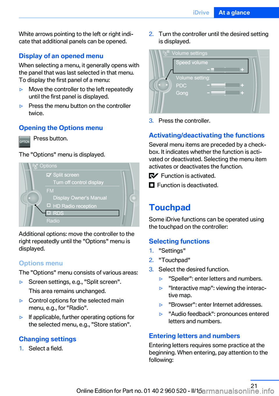
Opening the Options menu
Press button.
The "Options" menu is displayed.
Additional options: move the controller to the
right repeatedly until the "Options" menu is
displayed.
Options menu The "Options" menu consists of various areas:
▷Screen settings, e.g., "Split screen".
This area remains unchanged.▷Control options for the selected main
menu, e.g., for "Radio".▷If applicable, further operating options for
the selected menu, e.g., "Store station".
Changing settings
1.Select a field.2.Turn the controller until the desired setting
is displayed.3.Press the controller.
Activating/deactivating the functions
Several menu items are preceded by a check‐
box. It indicates whether the function is acti‐
vated or deactivated. Selecting the menu item
activates or deactivates the function.
Function is activated.
Function is deactivated.
Touchpad Some iDrive functions can be operated using
the touchpad on the controller:
Selecting functions
1."Settings"2."Touchpad"3.Select the desired function.▷"Speller": enter letters and numbers.▷"Interactive map": viewing the interac‐
tive map.▷"Browser": enter Internet addresses.▷"Audio feedback": pronounces entered
letters and numbers.
Entering letters and numbers
Entering letters requires some practice at the
beginning. When entering, pay attention to the
following:
Seite 21iDriveAt a glance21
Online Edition for Part no. 01 40 2 960 520 - II/15
Page 27 of 247
6.Turn the controller to set the hours and
press the controller.7.Turn the controller to set the minutes and
press the controller.
Status information
Status field The following information is displayed in the
status field at the top right:
▷Time.▷Current entertainment source.▷Sound output, on/off.▷Wireless network reception strength.▷Phone status.▷Traffic bulletin reception.
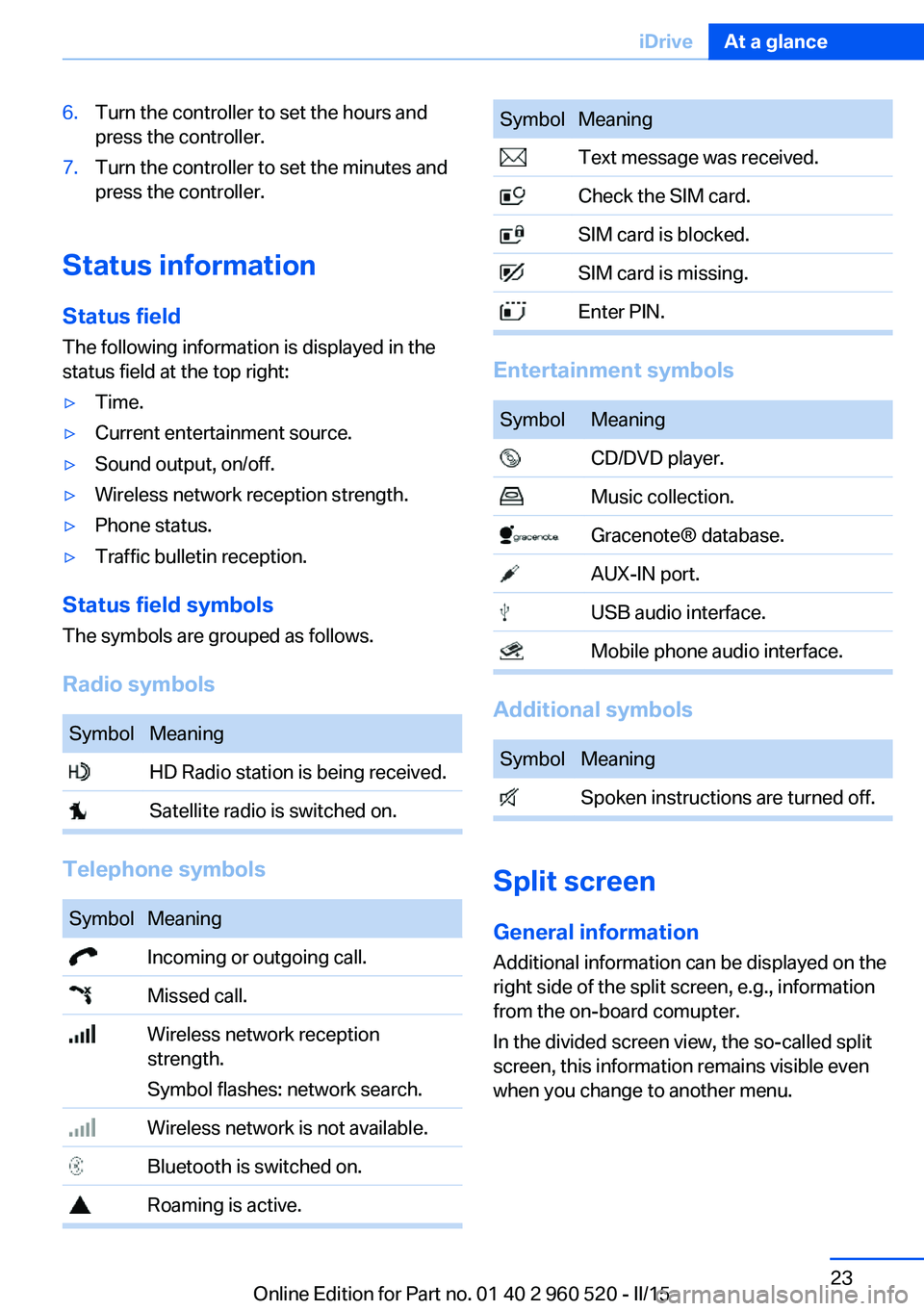
Status field symbols
The symbols are grouped as follows.
Radio symbols
SymbolMeaning HD Radio station is being received. Satellite radio is switched on.
Telephone symbols
SymbolMeaning Incoming or outgoing call. Missed call. Wireless network reception
strength.
Symbol flashes: network search. Wireless network is not available. Bluetooth is switched on. Roaming is active.SymbolMeaning Text message was received. Check the SIM card. SIM card is blocked. SIM card is missing. Enter PIN.
Entertainment symbols
SymbolMeaning CD/DVD player. Music collection. Gracenote® database. AUX-IN port. USB audio interface. Mobile phone audio interface.
Additional symbols
SymbolMeaning Spoken instructions are turned off.
Split screen
General information Additional information can be displayed on the
right side of the split screen, e.g., information
from the on-board comupter.
In the divided screen view, the so-called split
screen, this information remains visible even when you change to another menu.
Seite 23iDriveAt a glance23
Online Edition for Part no. 01 40 2 960 520 - II/15
Page 35 of 247
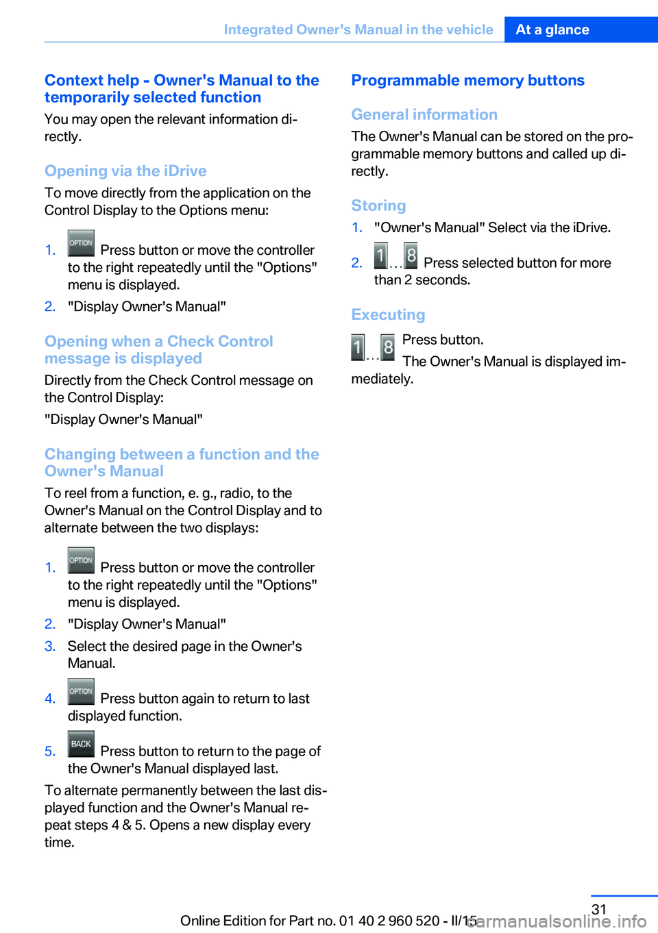
Context help - Owner's Manual to the
temporarily selected function
You may open the relevant information di‐
rectly.
Opening via the iDrive
To move directly from the application on the
Control Display to the Options menu:1. Press button or move the controller
to the right repeatedly until the "Options"
menu is displayed.2."Display Owner's Manual"
Opening when a Check Control
message is displayed
Directly from the Check Control message on
the Control Display:
"Display Owner's Manual"
Changing between a function and the
Owner's Manual
To reel from a function, e. g., radio, to the
Owner's Manual on the Control Display and to
alternate between the two displays:
1. Press button or move the controller
to the right repeatedly until the "Options"
menu is displayed.2."Display Owner's Manual"3.Select the desired page in the Owner's
Manual.4. Press button again to return to last
displayed function.5. Press button to return to the page of
the Owner's Manual displayed last.
To alternate permanently between the last dis‐
played function and the Owner's Manual re‐
peat steps 4 & 5. Opens a new display every
time.
Programmable memory buttons
General information
The Owner's Manual can be stored on the pro‐
grammable memory buttons and called up di‐
rectly.
Storing1."Owner's Manual" Select via the iDrive.2. Press selected button for more
than 2 seconds.
Executing
Press button.
The Owner's Manual is displayed im‐
mediately.
Seite 31Integrated Owner's Manual in the vehicleAt a glance31
Online Edition for Part no. 01 40 2 960 520 - II/15
Page 39 of 247
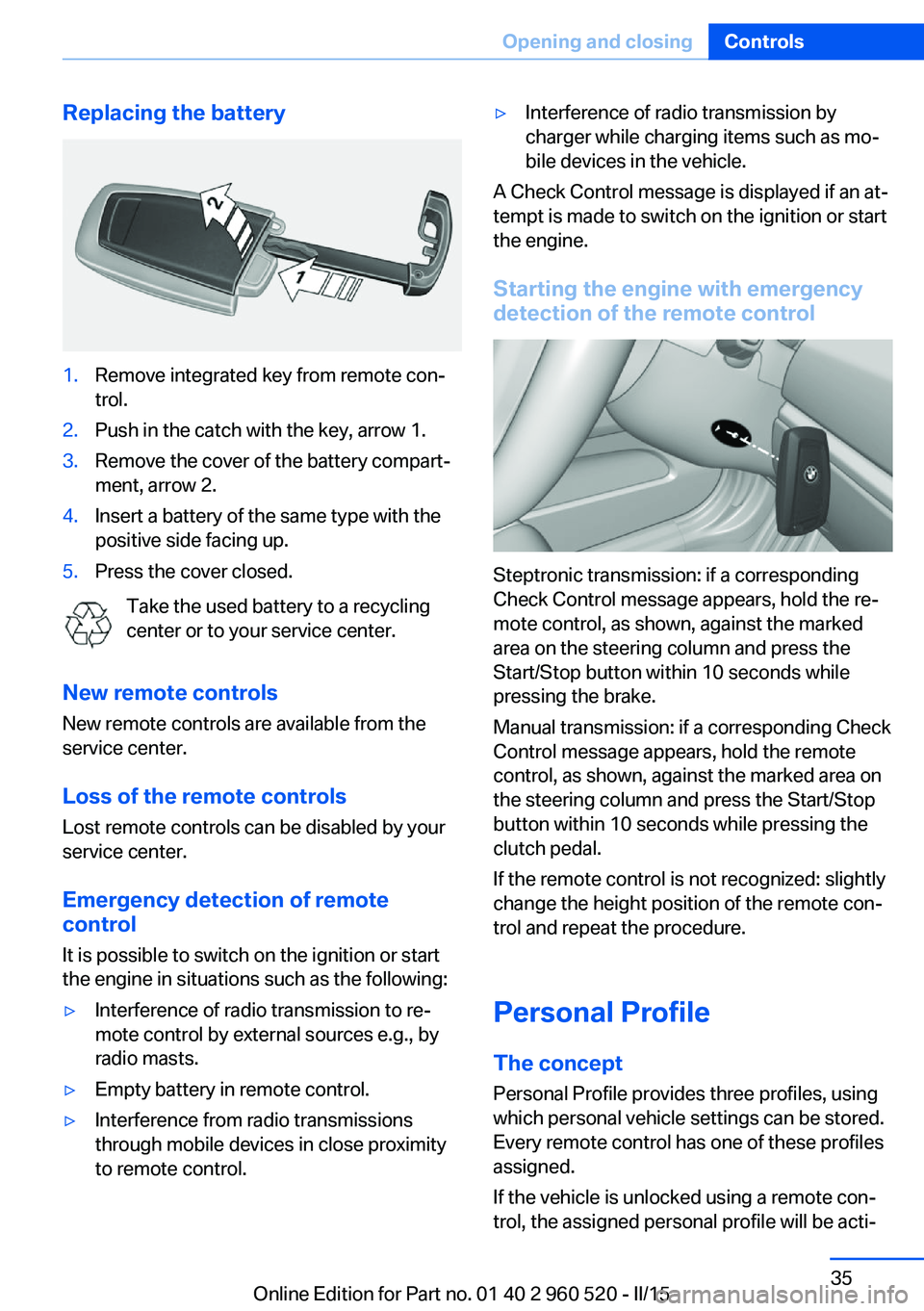
Replacing the battery1.Remove integrated key from remote con‐
trol.2.Push in the catch with the key, arrow 1.3.Remove the cover of the battery compart‐
ment, arrow 2.4.Insert a battery of the same type with the
positive side facing up.5.Press the cover closed.
Take the used battery to a recycling
center or to your service center.
New remote controls New remote controls are available from the
service center.
Loss of the remote controls Lost remote controls can be disabled by your
service center.
Emergency detection of remote
control
It is possible to switch on the ignition or start
the engine in situations such as the following:
▷Interference of radio transmission to re‐
mote control by external sources e.g., by
radio masts.▷Empty battery in remote control.▷Interference from radio transmissions
through mobile devices in close proximity
to remote control.▷Interference of radio transmission by
charger while charging items such as mo‐
bile devices in the vehicle.
A Check Control message is displayed if an at‐
tempt is made to switch on the ignition or start
the engine.
Starting the engine with emergency
detection of the remote control
Steptronic transmission: if a corresponding
Check Control message appears, hold the re‐
mote control, as shown, against the marked
area on the steering column and press the
Start/Stop button within 10 seconds while
pressing the brake.
Manual transmission: if a corresponding Check
Control message appears, hold the remote
control, as shown, against the marked area on
the steering column and press the Start/Stop
button within 10 seconds while pressing the
clutch pedal.
If the remote control is not recognized: slightly
change the height position of the remote con‐
trol and repeat the procedure.
Personal Profile
The concept Personal Profile provides three profiles, using
which personal vehicle settings can be stored.
Every remote control has one of these profiles
assigned.
If the vehicle is unlocked using a remote con‐
trol, the assigned personal profile will be acti‐
Seite 35Opening and closingControls35
Online Edition for Part no. 01 40 2 960 520 - II/15
Page 50 of 247
▷With Comfort Access: if you are carrying
the remote control on your person, grasp
the driver side or front passenger side door
handle completely.
Power windows
Hint Take the remote control with you
Take the remote control with you when
leaving the vehicle so that children, e.g., can‐
not operate the power windows and injure
themselves.◀
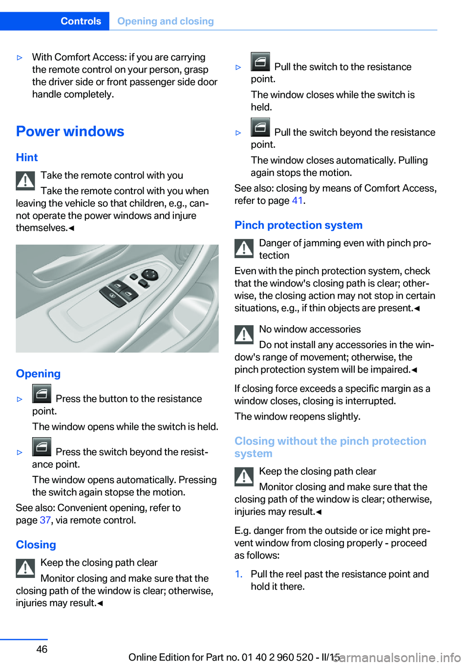
Opening
▷ Press the button to the resistance
point.
The window opens while the switch is held.▷ Press the switch beyond the resist‐
ance point.
The window opens automatically. Pressing
the switch again stopse the motion.
See also: Convenient opening, refer to
page 37, via remote control.
Closing Keep the closing path clear
Monitor closing and make sure that the
closing path of the window is clear; otherwise,
injuries may result.◀
▷ Pull the switch to the resistance
point.
The window closes while the switch is
held.▷ Pull the switch beyond the resistance
point.
The window closes automatically. Pulling
again stops the motion.
See also: closing by means of Comfort Access,
refer to page 41.
Pinch protection system Danger of jamming even with pinch pro‐
tection
Even with the pinch protection system, check
that the window's closing path is clear; other‐
wise, the closing action may not stop in certain
situations, e.g., if thin objects are present.◀
No window accessories
Do not install any accessories in the win‐
dow's range of movement; otherwise, the
pinch protection system will be impaired.◀
If closing force exceeds a specific margin as a
window closes, closing is interrupted.
The window reopens slightly.
Closing without the pinch protection
system
Keep the closing path clear
Monitor closing and make sure that the
closing path of the window is clear; otherwise,
injuries may result.◀
E.g. danger from the outside or ice might pre‐
vent window from closing properly - proceed
as follows:
1.Pull the reel past the resistance point and
hold it there.Seite 46ControlsOpening and closing46
Online Edition for Part no. 01 40 2 960 520 - II/15
Page 52 of 247
▷Closing by means of Comfort Access, refer
to page 41.
Comfort position
If the glass sunroof is not automatically com‐
pletely opened, the comfort position has been
attained. In this position the wind noises in the
interior are the least.
If desired, continue the movement by pressing
the reel.
Pinch protection system
If the closing force when closing the glass sun‐
roof exceeds a certain value, the closing move‐
ment is stopped, beginning at approximately
the middle of the opening in the roof, or from
the tilted position during closing.
The glass sunroof reopens slightly.
Danger of jamming even with pinch pro‐
tection
Despite the pinch protection system, check
that the glass sunroof's closing path is clear;
otherwise, the closing action may not be inter‐
rupted in certain extreme situations, such as
when thin objects are present.◀
Closing from the open position
without pinch protection
E. g. if there is an external danger, proceed as
follows:
1.Press the reel forward beyond the resist‐
ance point and hold.
The pinch protection is limited and the
glass sunroof reopens slightly if the closing
force exceeds a certain margin.2.Press the reel forward again beyond the re‐
sistance point and hold until the glass sun‐
roof closes without jam protection. Make
sure that the closing area is clear.Closing from the raised position
without pinch protection
If there is an external danger, push the reel for‐
ward past the resistance point and hold it.
The glass sunroof closes without jam protec‐
tion.
Initializing after a power failure After a power failure during the opening or
closing process, the glass sunroof can only be
operated to a limited extent.
Initializing the system
The system can be initialized when the vehicle
is stationary and the engine is running.
During the initialization, the glass sunroof
closes without jam protection.
Keep the closing path clear
Monitor closing and make sure that the
closing path of the glass sunroof is clear; oth‐
erwise, injuries may result.◀
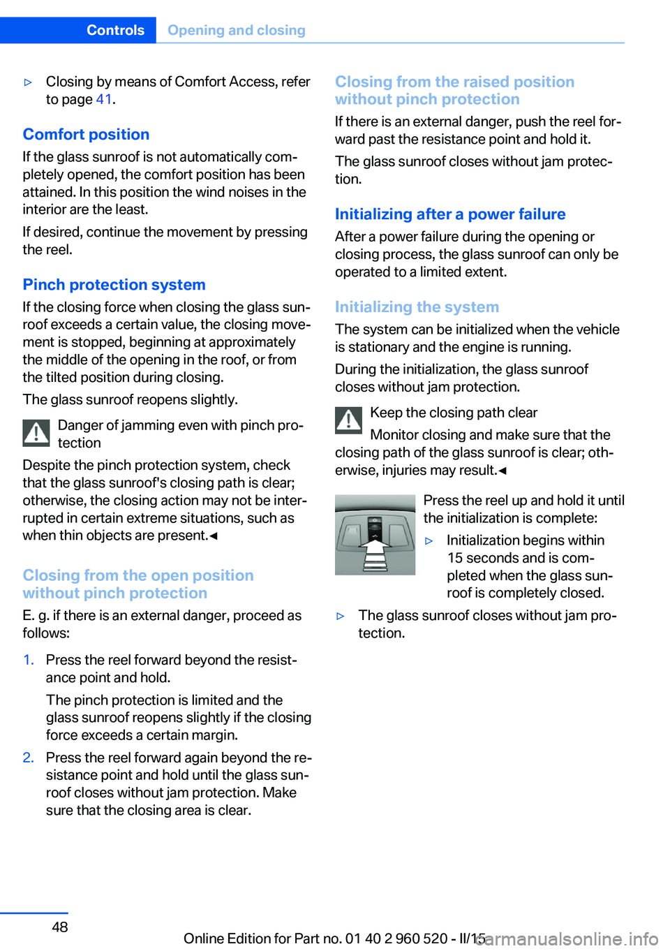
Press the reel up and hold it until
the initialization is complete:▷Initialization begins within
15 seconds and is com‐
pleted when the glass sun‐
roof is completely closed.▷The glass sunroof closes without jam pro‐
tection.Seite 48ControlsOpening and closing48
Online Edition for Part no. 01 40 2 960 520 - II/15
Page 58 of 247
Safety belt reminder for driver's and
passenger's seat
The indicator lamp lights up and a sig‐
nal sounds. Make sure that the safety
belts are positioned correctly. The
safety belt reminder is active at speeds above
approx. 6 mph/10 km/h. It can also be activated
if objects are placed on the front passenger
seat.
Damage to safety belts Wear and tear after accidents or when dam‐
aged otherwise:
Have the safety belts, including the safety belt
tensioners, replaced and have the belt anchors
checked.
Check and replace safety belts
This should only be done by your service
center; otherwise, this safety feature might not
work properly.◀
Belt carrier
The concept The belt carrier makes it easier to put on the
safety belt.
General information
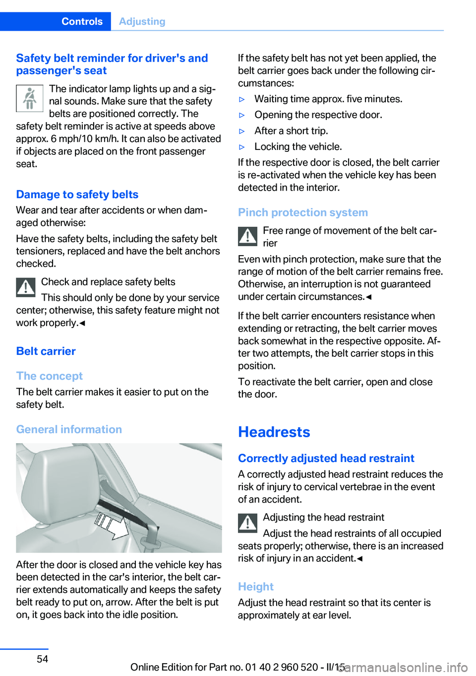
After the door is closed and the vehicle key has
been detected in the car's interior, the belt car‐
rier extends automatically and keeps the safety
belt ready to put on, arrow. After the belt is put
on, it goes back into the idle position.
If the safety belt has not yet been applied, the
belt carrier goes back under the following cir‐
cumstances:▷Waiting time approx. five minutes.▷Opening the respective door.▷After a short trip.▷Locking the vehicle.
If the respective door is closed, the belt carrier
is re-activated when the vehicle key has been
detected in the interior.
Pinch protection system Free range of movement of the belt car‐
rier
Even with pinch protection, make sure that the
range of motion of the belt carrier remains free.
Otherwise, an interruption is not guaranteed
under certain circumstances.◀
If the belt carrier encounters resistance when
extending or retracting, the belt carrier moves
back somewhat in the respective opposite. Af‐
ter two attempts, the belt carrier stops in this
position.
To reactivate the belt carrier, open and close
the door.
Headrests
Correctly adjusted head restraint A correctly adjusted head restraint reduces the
risk of injury to cervical vertebrae in the event
of an accident.
Adjusting the head restraint
Adjust the head restraints of all occupied
seats properly; otherwise, there is an increased
risk of injury in an accident.◀
Height Adjust the head restraint so that its center is
approximately at ear level.
Seite 54ControlsAdjusting54
Online Edition for Part no. 01 40 2 960 520 - II/15
Page 71 of 247
▷LED goes out: Auto Start/Stop function is
activated.
Switching off the vehicle during an
automatic engine stop
During an automatic engine stop, the vehicle
can be switched off permanently, e. g., when
leaving it.
1.Press the Start/Stop button. The ignition is
switched off. The Auto Start/Stop function
is deactivated.
Selector lever position P is engaged auto‐
matically.2.Set the parking brake.
Engine start as usual via Start/Stop button.
Automatic deactivation
In certain situations, Auto Start/Stop function
is deactivated automatically for safety reasons
as if the driver were absent.
Malfunction
The Auto Start/Stop function no longer
switches off the engine automatically. A Check
Control message is displayed. It is possible to
continue driving. Have the system checked.
Parking brake Applying
The lever automatically engages after being
pulled up.
The indicator lamp lights up red. The
parking brake is set.
Lower lamp: indicator lamp in Canadian
models
Releasing
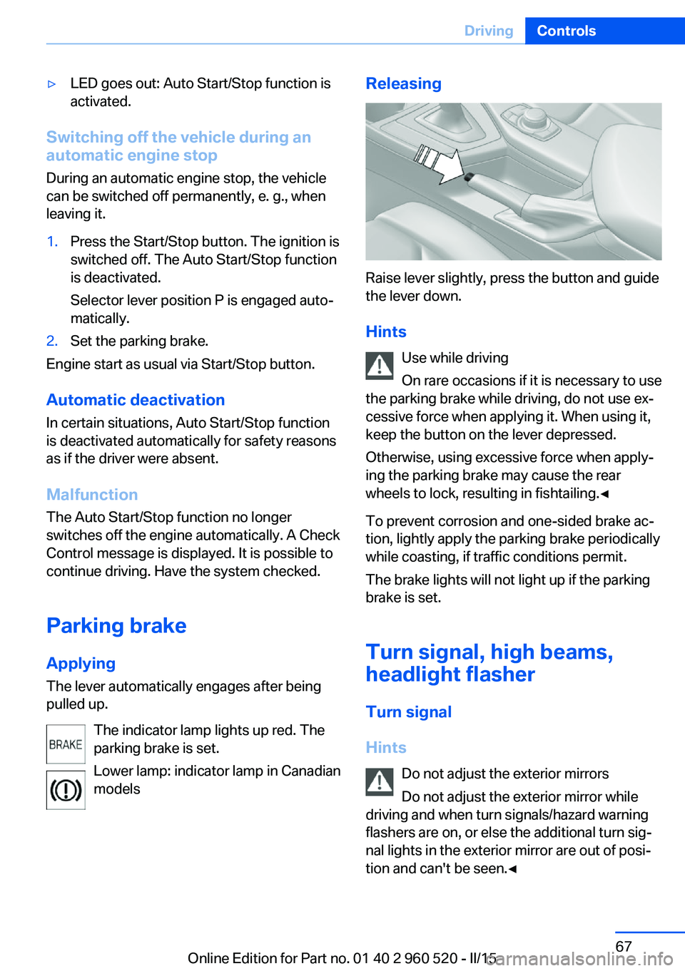
Raise lever slightly, press the button and guide
the lever down.
Hints Use while driving
On rare occasions if it is necessary to use
the parking brake while driving, do not use ex‐
cessive force when applying it. When using it,
keep the button on the lever depressed.
Otherwise, using excessive force when apply‐
ing the parking brake may cause the rear
wheels to lock, resulting in fishtailing.◀
To prevent corrosion and one-sided brake ac‐
tion, lightly apply the parking brake periodically
while coasting, if traffic conditions permit.
The brake lights will not light up if the parking
brake is set.
Turn signal, high beams,
headlight flasher
Turn signal
Hints Do not adjust the exterior mirrors
Do not adjust the exterior mirror while
driving and when turn signals/hazard warning
flashers are on, or else the additional turn sig‐
nal lights in the exterior mirror are out of posi‐
tion and can't be seen.◀
Seite 67DrivingControls67
Online Edition for Part no. 01 40 2 960 520 - II/15