battery BMW 435I XDRIVE CONVERTIBLE 2016 User Guide
[x] Cancel search | Manufacturer: BMW, Model Year: 2016, Model line: 435I XDRIVE CONVERTIBLE, Model: BMW 435I XDRIVE CONVERTIBLE 2016Pages: 247, PDF Size: 5.22 MB
Page 71 of 247
Some indicator lights light up for a varied
length of time.
The engine can only be started via the Start/
Stop button.
Functional limitations
Even if driving off was not intended, the deacti‐
vated engine starts up automatically in the fol‐
lowing situations:▷Excessive warming of the car's interior
when the cooling function is switched on.▷The steering wheel is turned.▷Steptronic transmission: change from se‐
lector lever position D to R, N or M/S.▷Steptronic transmission: change from se‐
lector lever position P to N, D, R or M/S.▷Fogging of the windows when the auto‐
matic climate control is switched on.▷Vehicle battery is heavily discharged.▷Excessive cooling of the car's interior when
the heating is switched on.
Activating/deactivating the system
manually
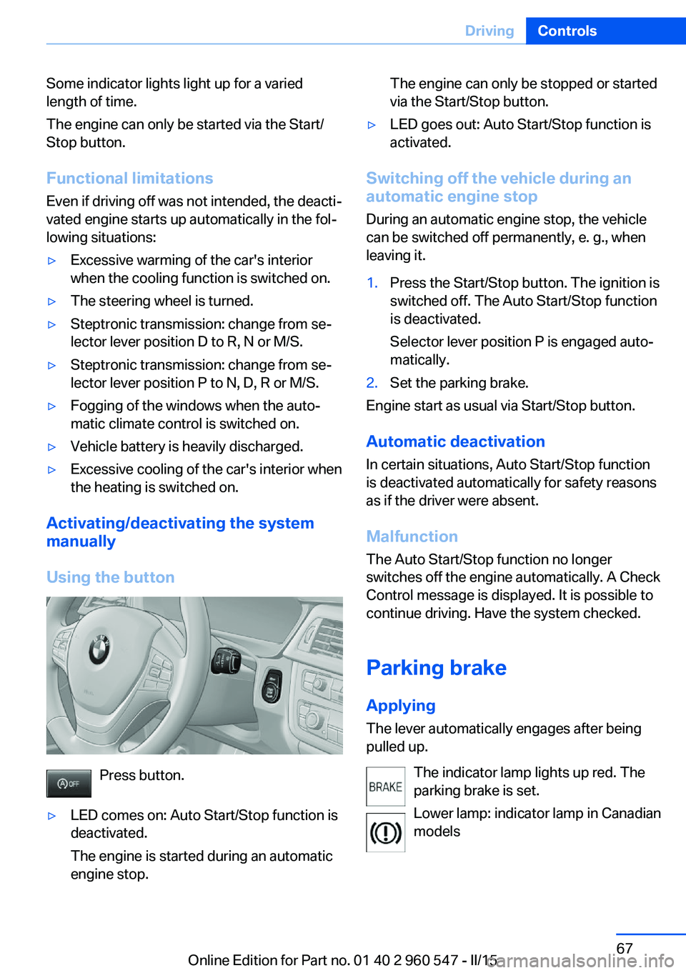
Using the button
Press button.
▷LED comes on: Auto Start/Stop function is
deactivated.
The engine is started during an automatic
engine stop.The engine can only be stopped or started
via the Start/Stop button.▷LED goes out: Auto Start/Stop function is
activated.
Switching off the vehicle during an
automatic engine stop
During an automatic engine stop, the vehicle
can be switched off permanently, e. g., when
leaving it.
1.Press the Start/Stop button. The ignition is
switched off. The Auto Start/Stop function
is deactivated.
Selector lever position P is engaged auto‐
matically.2.Set the parking brake.
Engine start as usual via Start/Stop button.
Automatic deactivation
In certain situations, Auto Start/Stop function
is deactivated automatically for safety reasons
as if the driver were absent.
Malfunction
The Auto Start/Stop function no longer
switches off the engine automatically. A Check
Control message is displayed. It is possible to
continue driving. Have the system checked.
Parking brake Applying
The lever automatically engages after being
pulled up.
The indicator lamp lights up red. The
parking brake is set.
Lower lamp: indicator lamp in Canadian
models
Seite 67DrivingControls67
Online Edition for Part no. 01 40 2 960 547 - II/15
Page 95 of 247
LightsVehicle features and optionsThis chapter describes all standard, country-
specific and optional features offered with the
series. It also describes features that are not
necessarily available in your car, e. g., due to
the selected options or country versions. This
also applies to safety-related functions and
systems. The respectively applicable country
provisions must be observed when using the
respective features and systems.
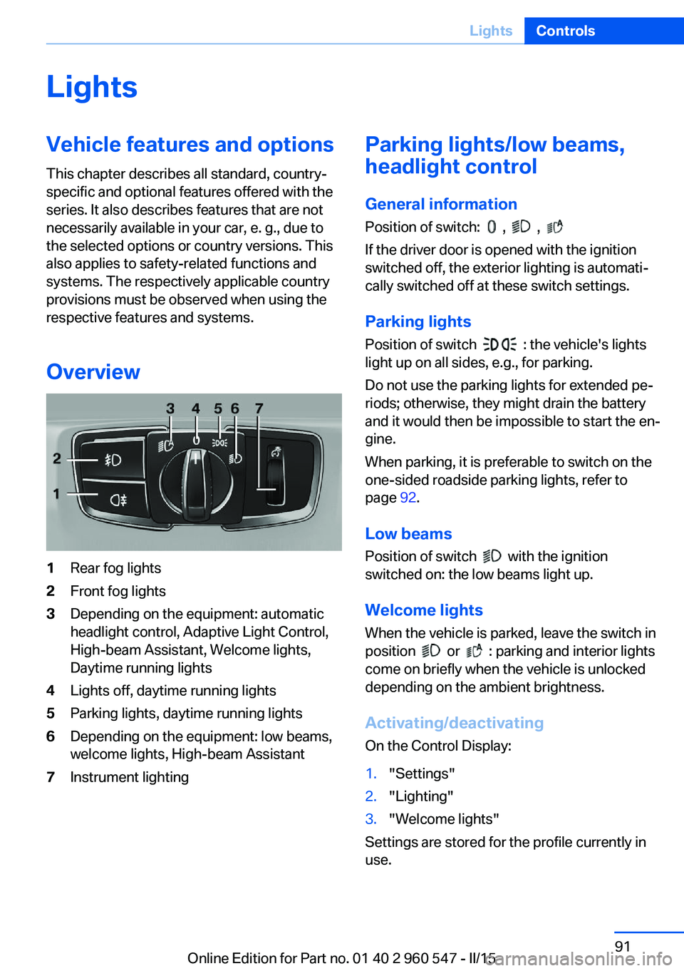
Overview1Rear fog lights2Front fog lights3Depending on the equipment: automatic
headlight control, Adaptive Light Control,
High-beam Assistant, Welcome lights,
Daytime running lights4Lights off, daytime running lights5Parking lights, daytime running lights6Depending on the equipment: low beams,
welcome lights, High-beam Assistant7Instrument lightingParking lights/low beams,
headlight control
General information
Position of switch:
, ,
If the driver door is opened with the ignition
switched off, the exterior lighting is automati‐
cally switched off at these switch settings.
Parking lights
Position of switch
: the vehicle's lights
light up on all sides, e.g., for parking.
Do not use the parking lights for extended pe‐
riods; otherwise, they might drain the battery
and it would then be impossible to start the en‐
gine.
When parking, it is preferable to switch on the
one-sided roadside parking lights, refer to
page 92.
Low beams Position of switch
with the ignition
switched on: the low beams light up.
Welcome lights
When the vehicle is parked, leave the switch in
position
or : parking and interior lights
come on briefly when the vehicle is unlocked
depending on the ambient brightness.
Activating/deactivating
On the Control Display:
1."Settings"2."Lighting"3."Welcome lights"
Settings are stored for the profile currently in
use.
Seite 91LightsControls91
Online Edition for Part no. 01 40 2 960 547 - II/15
Page 150 of 247
Climate control functions in detail
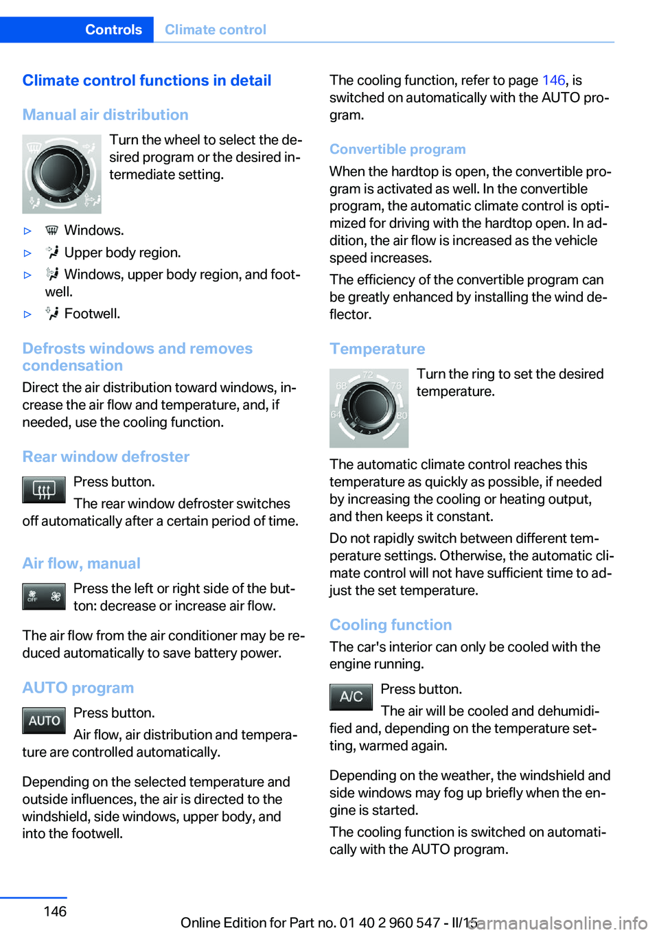
Manual air distribution Turn the wheel to select the de‐
sired program or the desired in‐
termediate setting.▷ Windows.▷ Upper body region.▷ Windows, upper body region, and foot‐
well.▷ Footwell.
Defrosts windows and removes
condensation
Direct the air distribution toward windows, in‐
crease the air flow and temperature, and, if
needed, use the cooling function.
Rear window defroster Press button.
The rear window defroster switches
off automatically after a certain period of time.
Air flow, manual Press the left or right side of the but‐
ton: decrease or increase air flow.
The air flow from the air conditioner may be re‐
duced automatically to save battery power.
AUTO program Press button.
Air flow, air distribution and tempera‐
ture are controlled automatically.
Depending on the selected temperature and
outside influences, the air is directed to the
windshield, side windows, upper body, and
into the footwell.
The cooling function, refer to page 146, is
switched on automatically with the AUTO pro‐
gram.
Convertible program
When the hardtop is open, the convertible pro‐
gram is activated as well. In the convertible
program, the automatic climate control is opti‐
mized for driving with the hardtop open. In ad‐
dition, the air flow is increased as the vehicle
speed increases.
The efficiency of the convertible program can
be greatly enhanced by installing the wind de‐
flector.
Temperature Turn the ring to set the desired
temperature.
The automatic climate control reaches this
temperature as quickly as possible, if needed
by increasing the cooling or heating output,
and then keeps it constant.
Do not rapidly switch between different tem‐
perature settings. Otherwise, the automatic cli‐
mate control will not have sufficient time to ad‐
just the set temperature.
Cooling function
The car's interior can only be cooled with the
engine running.
Press button.
The air will be cooled and dehumidi‐
fied and, depending on the temperature set‐
ting, warmed again.
Depending on the weather, the windshield and
side windows may fog up briefly when the en‐
gine is started.
The cooling function is switched on automati‐
cally with the AUTO program.Seite 146ControlsClimate control146
Online Edition for Part no. 01 40 2 960 547 - II/15
Page 154 of 247
▷Left LED on, automatic recirculated-air
control: a sensor detects pollutants in the
outside air and shuts off automatically.▷Right LED on, recirculated-air mode: the
supply of outside air into the vehicle is per‐
manently blocked.
Recirculated air mode switches off automati‐
cally at low external temperatures after a cer‐
tain amount of time in order to avoid window
fogging.
If the windows are fogged over, switch off the
recirculated-air mode and press the AUTO
button to utilize the condensation sensor.
Make sure that air can flow to the windshield.
Sufficient ventilation
When remaining in the vehicle for an ex‐
tended period of time, ensure sufficient exter‐
nal ventilation. Do not continuously use recir‐
culated-air mode; otherwise the air quality in
the interior continuously deteriorates and win‐
dow condensation increases.◀
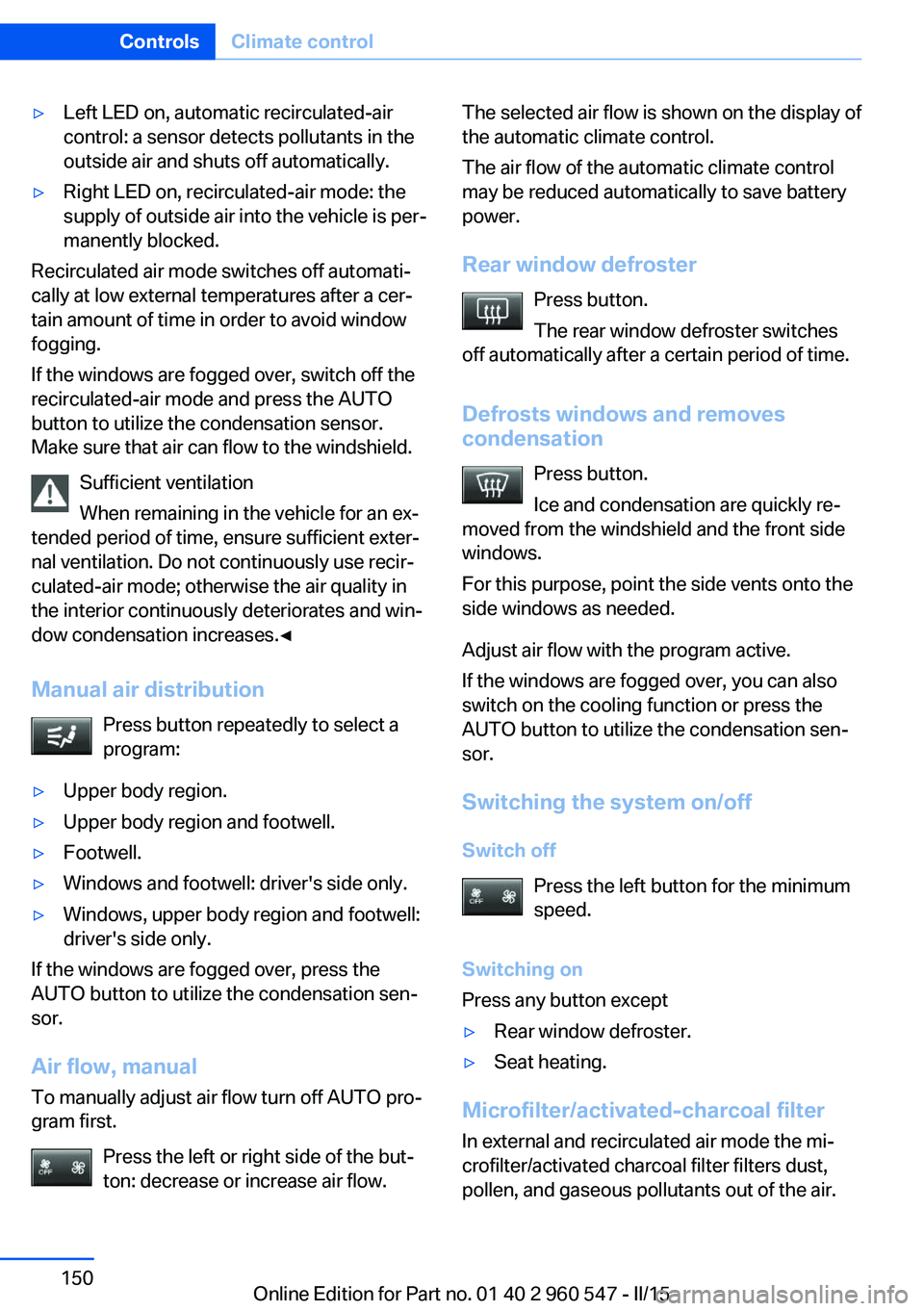
Manual air distribution Press button repeatedly to select a
program:
▷Upper body region.▷Upper body region and footwell.▷Footwell.▷Windows and footwell: driver's side only.▷Windows, upper body region and footwell:
driver's side only.
If the windows are fogged over, press the
AUTO button to utilize the condensation sen‐
sor.
Air flow, manual
To manually adjust air flow turn off AUTO pro‐
gram first.
Press the left or right side of the but‐
ton: decrease or increase air flow.
The selected air flow is shown on the display of
the automatic climate control.
The air flow of the automatic climate control
may be reduced automatically to save battery
power.
Rear window defroster Press button.
The rear window defroster switches
off automatically after a certain period of time.
Defrosts windows and removes
condensation
Press button.
Ice and condensation are quickly re‐
moved from the windshield and the front side
windows.
For this purpose, point the side vents onto the
side windows as needed.
Adjust air flow with the program active.
If the windows are fogged over, you can also
switch on the cooling function or press the
AUTO button to utilize the condensation sen‐
sor.
Switching the system on/off
Switch off Press the left button for the minimum
speed.
Switching on
Press any button except▷Rear window defroster.▷Seat heating.
Microfilter/activated-charcoal filter
In external and recirculated air mode the mi‐
crofilter/activated charcoal filter filters dust,
pollen, and gaseous pollutants out of the air.
Seite 150ControlsClimate control150
Online Edition for Part no. 01 40 2 960 547 - II/15
Page 161 of 247
Settings are stored automatically after approxi‐
mately 10 seconds.
Sun visor
Glare shield Fold the sun visor down or up.
Vanity mirror A vanity mirror is located in the sun visor be‐
hind a cover. When the cover is opened, the
mirror lighting switches on.
Ashtray/cigarette lighterAshtray
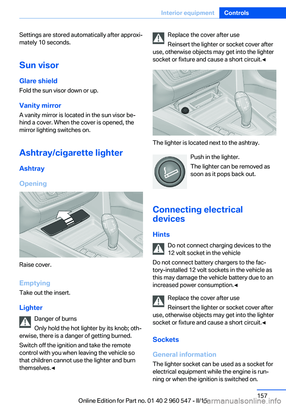
Opening
Raise cover.
EmptyingTake out the insert.
Lighter Danger of burns
Only hold the hot lighter by its knob; oth‐
erwise, there is a danger of getting burned.
Switch off the ignition and take the remote
control with you when leaving the vehicle so
that children cannot use the lighter and burn
themselves.◀
Replace the cover after use
Reinsert the lighter or socket cover after
use, otherwise objects may get into the lighter
socket or fixture and cause a short circuit.◀
The lighter is located next to the ashtray.
Push in the lighter.
The lighter can be removed as
soon as it pops back out.
Connecting electrical devices
Hints Do not connect charging devices to the
12 volt socket in the vehicle
Do not connect battery chargers to the fac‐
tory-installed 12 volt sockets in the vehicle as
this may damage the vehicle battery due to an
increased power consumption.◀
Replace the cover after use
Reinsert the lighter or socket cover after
use, otherwise objects may get into the lighter
socket or fixture and cause a short circuit.◀
Sockets
General information
The lighter socket can be used as a socket for
electrical equipment while the engine is run‐ ning or when the ignition is switched on.
Seite 157Interior equipmentControls157
Online Edition for Part no. 01 40 2 960 547 - II/15
Page 181 of 247
Vertical bars show consumption for the se‐
lected time frame.
Trip interruptions are represented below the
bar on the time axis.
"Consumption history"
Adjusting fuel consumption history time frame
Select the symbol.
Resetting fuel consumption history
1.Open "Options".2."Reset consumption history"
Displaying EfficientDynamics info
The current efficiency can be displayed.
"EfficientDynamics info"
The following systems are displayed:
▷Auto Start/Stop function.▷Energy recovery.▷Climate control output.▷Coasting.
Display ECO PRO tips
"ECO PRO Tips"
Settings are stored for the profile currently in
use.
Coasting
The concept
The system helps to conserve fuel.
To do this, under certain conditions the engine
is automatically decoupled from the transmis‐
sion when selector lever position D is set. The
vehicle continues traveling with the engine
idling to reduce fuel consumption. Selector
lever position D remains engaged.
This driving condition is referred to as coast‐
ing.
As soon as you step on the brake or accelera‐
tor pedal, the engine is automatically coupled
again.
Hints
Coasting is a component of the ECO PRO, re‐
fer to page 174, driving mode.
Coasting is automatically activated when ECO
PRO mode is called via the Driving Dynamics
Control.
The function is available in a certain speed
range.
A proactively driving style helps the driver to
use the function as often as possible and sup‐
ports the fuel-conserving effect of coasting.
Safety mode
The function is not available under one of the
following conditions.▷DSC OFF or TRACTION activated.▷Driving in the dynamic limit range and on
steep uphill or downhill grades.▷Battery charge status temporarily too low
or vehicle electrical system drawing exces‐
sive current.▷Cruise control activated.
Functional requirements
In ECO PRO mode, this function is available in
a speed range from approximately 30 mph, ap‐
prox. 50 km/h to 100 mph, approx. 160 km/h, if
the following conditions are met:
▷Accelerator pedal and brake pedal are not
operated.▷The selector lever is in selector lever posi‐
tion D.▷Engine and transmission are at operating
temperature.
The driving status Coast can be influenced
with the shift paddles.
Seite 177Saving fuelDriving tips177
Online Edition for Part no. 01 40 2 960 547 - II/15
Page 203 of 247
Engine compartmentVehicle features and optionsThis chapter describes all standard, country-
specific and optional features offered with the
series. It also describes features that are not
necessarily available in your car, e. g., due tothe selected options or country versions. This
also applies to safety-related functions and
systems. The respectively applicable country
provisions must be observed when using the
respective features and systems.
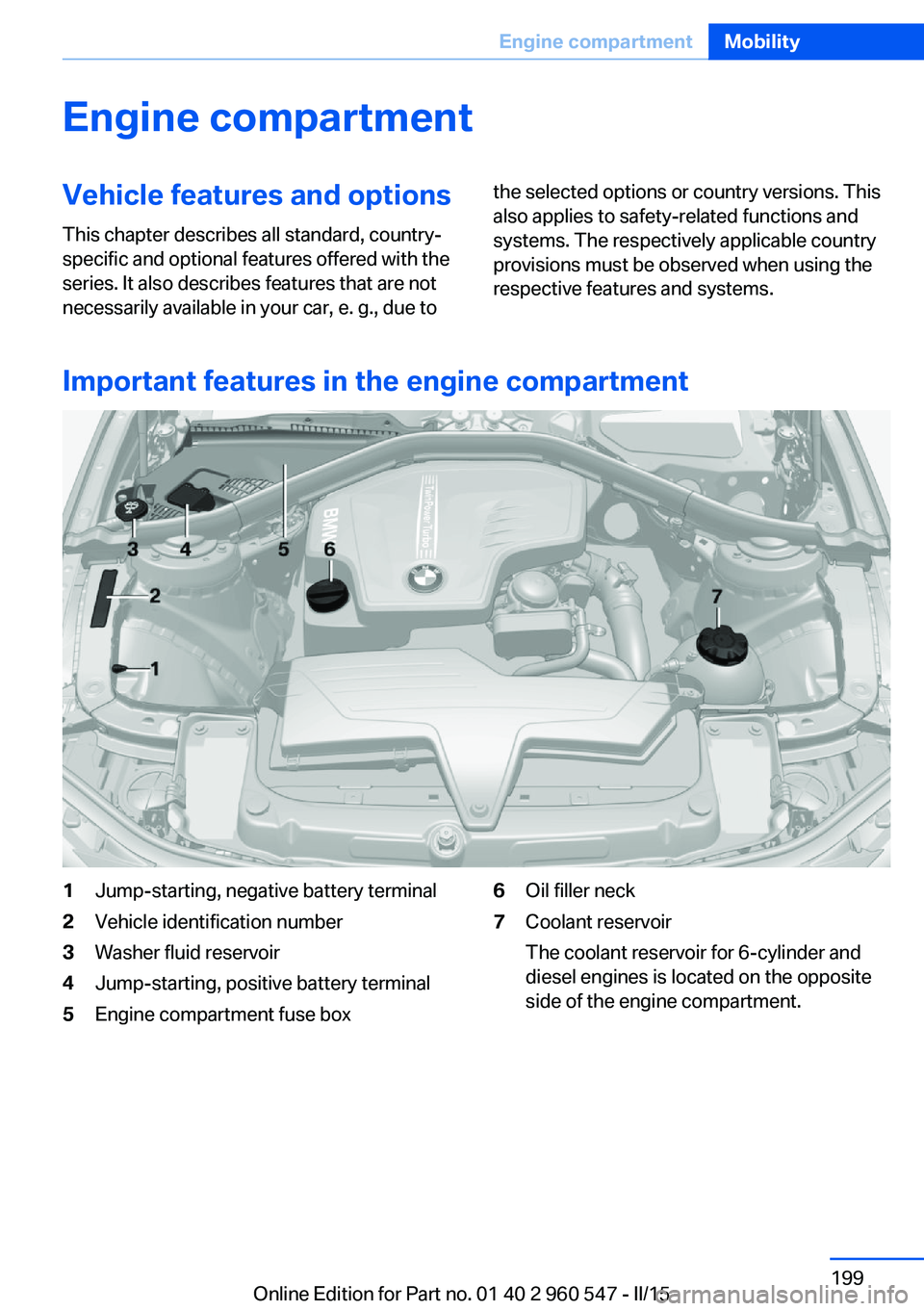
Important features in the engine compartment
1Jump-starting, negative battery terminal2Vehicle identification number3Washer fluid reservoir4Jump-starting, positive battery terminal5Engine compartment fuse box6Oil filler neck7Coolant reservoir
The coolant reservoir for 6-cylinder and
diesel engines is located on the opposite
side of the engine compartment.Seite 199Engine compartmentMobility199
Online Edition for Part no. 01 40 2 960 547 - II/15
Page 217 of 247
These lights are made using LED technology.
Contact your service center in the event of a
malfunction.
Changing wheels
Hints When using run-flat tires or sealants, a tire
does not need to be changed immediately in
the event of pressure loss due to a flat tire.
Which is why no spare tire is available.
The tools for changing wheels are available as
accessories from your service center.
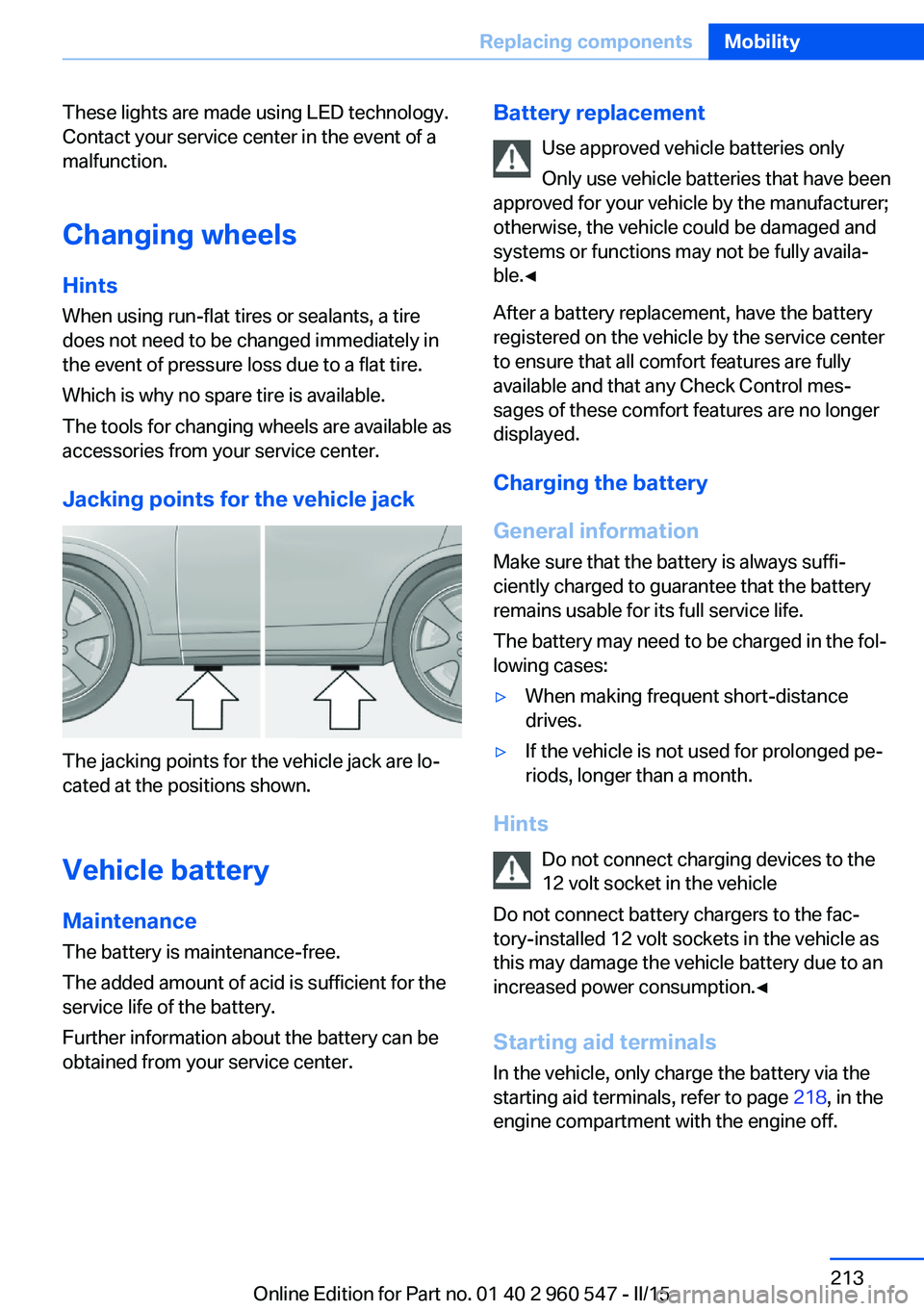
Jacking points for the vehicle jack
The jacking points for the vehicle jack are lo‐
cated at the positions shown.
Vehicle battery Maintenance
The battery is maintenance-free.
The added amount of acid is sufficient for the
service life of the battery.
Further information about the battery can be
obtained from your service center.
Battery replacement
Use approved vehicle batteries only
Only use vehicle batteries that have been
approved for your vehicle by the manufacturer;
otherwise, the vehicle could be damaged and
systems or functions may not be fully availa‐
ble.◀
After a battery replacement, have the battery registered on the vehicle by the service center
to ensure that all comfort features are fully
available and that any Check Control mes‐
sages of these comfort features are no longer
displayed.
Charging the battery
General information Make sure that the battery is always suffi‐
ciently charged to guarantee that the battery
remains usable for its full service life.
The battery may need to be charged in the fol‐
lowing cases:▷When making frequent short-distance
drives.▷If the vehicle is not used for prolonged pe‐
riods, longer than a month.
Hints
Do not connect charging devices to the
12 volt socket in the vehicle
Do not connect battery chargers to the fac‐
tory-installed 12 volt sockets in the vehicle as
this may damage the vehicle battery due to an
increased power consumption.◀
Starting aid terminals
In the vehicle, only charge the battery via the
starting aid terminals, refer to page 218, in the
engine compartment with the engine off.
Seite 213Replacing componentsMobility213
Online Edition for Part no. 01 40 2 960 547 - II/15
Page 218 of 247
Power failureAfter a temporary power loss, some equipment
needs to be newly initialized or individual set‐
tings updated, e. g.:▷Seat and mirror memory: store the posi‐
tions again.▷Time: update.▷Date: update.
Disposing of old batteries
Have old batteries disposed of by your
service center or bring them to a recy‐
cling center.
Maintain the battery in an upright position for
transport and storage. Secure the battery so
that it does not tip over during transport.
Fuses Hints Replacing fuses
Never attempt to repair a blown fuse and
do not replace a defective fuse with a substi‐
tute of another color or amperage rating; this
could lead to a circuit overload, ultimately re‐
sulting in a fire in the vehicle.◀
Plastic tweezers and information on the fuse
types and locations are stored in the fuse box
in the trunk.
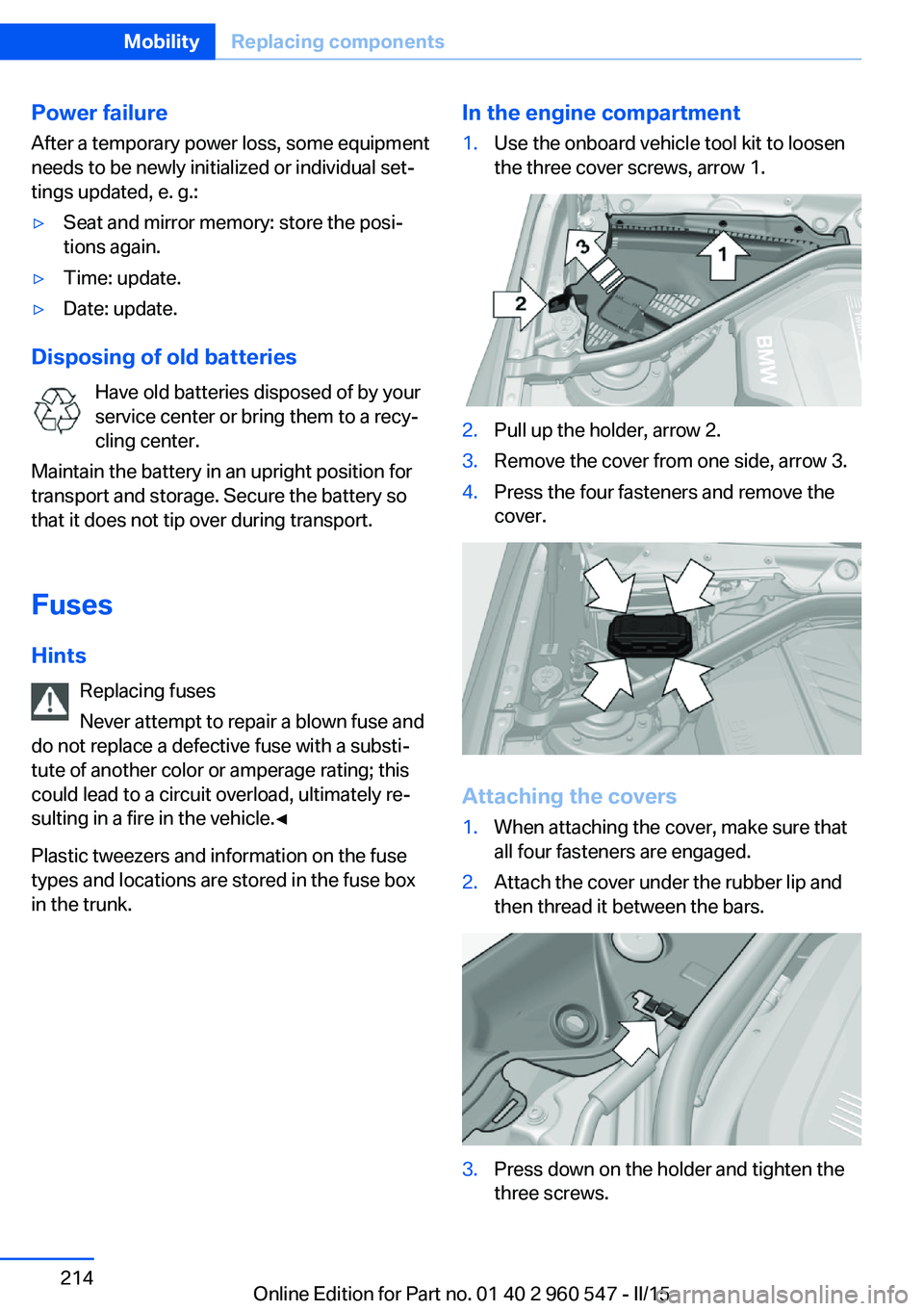
In the engine compartment1.Use the onboard vehicle tool kit to loosen
the three cover screws, arrow 1.2.Pull up the holder, arrow 2.3.Remove the cover from one side, arrow 3.4.Press the four fasteners and remove the
cover.
Attaching the covers
1.When attaching the cover, make sure that
all four fasteners are engaged.2.Attach the cover under the rubber lip and
then thread it between the bars.3.Press down on the holder and tighten the
three screws.Seite 214MobilityReplacing components214
Online Edition for Part no. 01 40 2 960 547 - II/15
Page 221 of 247
When the emergency request is received
at the BMW Response Center, the BMW
Response Center contacts you and takes
further steps to help you.
Even if you are unable to respond, the
BMW Response Center can take further
steps to help you under certain circum‐
stances.
For this, data are transmitted to the BMW
Response Center which serve to deter‐
mine the necessary rescue measures. E. g.
the current position of the vehicle, if it can
be established.▷If the LED is flashing green, but the BMW
Response Center can no longer be heard
via the speaker, you can nevertheless still
be heard at the BMW Response Center.
Initiating an Emergency Request
automatically
Under certain conditions, an Emergency Re‐
quest is automatically initiated immediately af‐
ter a severe accident. Automatic Collision Noti‐
fication is not affected by pressing the SOS
button.
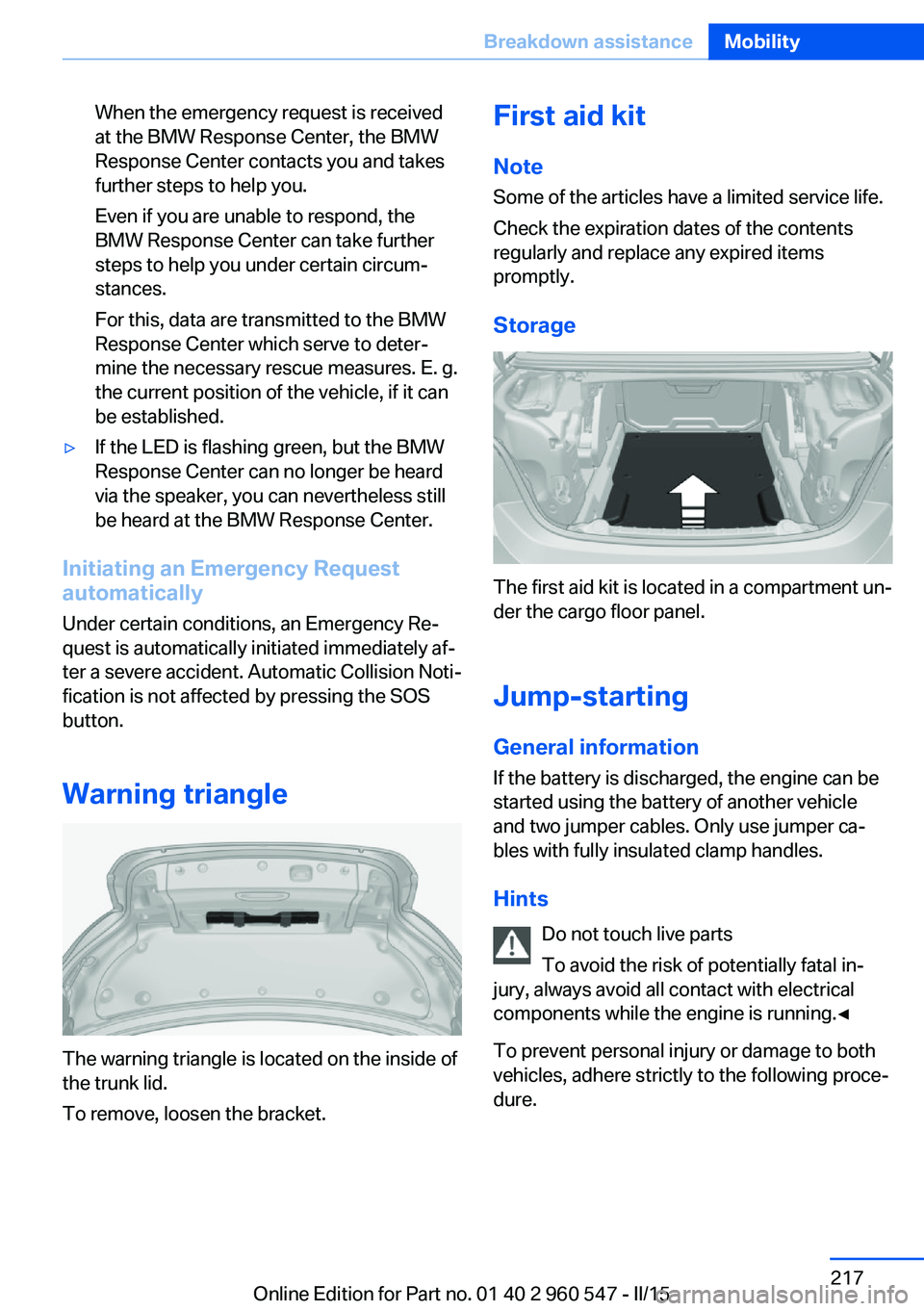
Warning triangle
The warning triangle is located on the inside of
the trunk lid.
To remove, loosen the bracket.
First aid kit
Note
Some of the articles have a limited service life.
Check the expiration dates of the contents
regularly and replace any expired items
promptly.
Storage
The first aid kit is located in a compartment un‐
der the cargo floor panel.
Jump-starting
General information If the battery is discharged, the engine can be
started using the battery of another vehicle
and two jumper cables. Only use jumper ca‐
bles with fully insulated clamp handles.
Hints Do not touch live parts
To avoid the risk of potentially fatal in‐
jury, always avoid all contact with electrical
components while the engine is running.◀
To prevent personal injury or damage to both
vehicles, adhere strictly to the following proce‐
dure.
Seite 217Breakdown assistanceMobility217
Online Edition for Part no. 01 40 2 960 547 - II/15