heat BMW 5 SERIES 1990 E34 Owner's Manual
[x] Cancel search | Manufacturer: BMW, Model Year: 1990, Model line: 5 SERIES, Model: BMW 5 SERIES 1990 E34Pages: 228, PDF Size: 7.04 MB
Page 82 of 228
disconnect the fluid cooler lines from the
radiator. Use a drip tray to catch spilled fluid.
Plug the fluid cooler lines and fittings.
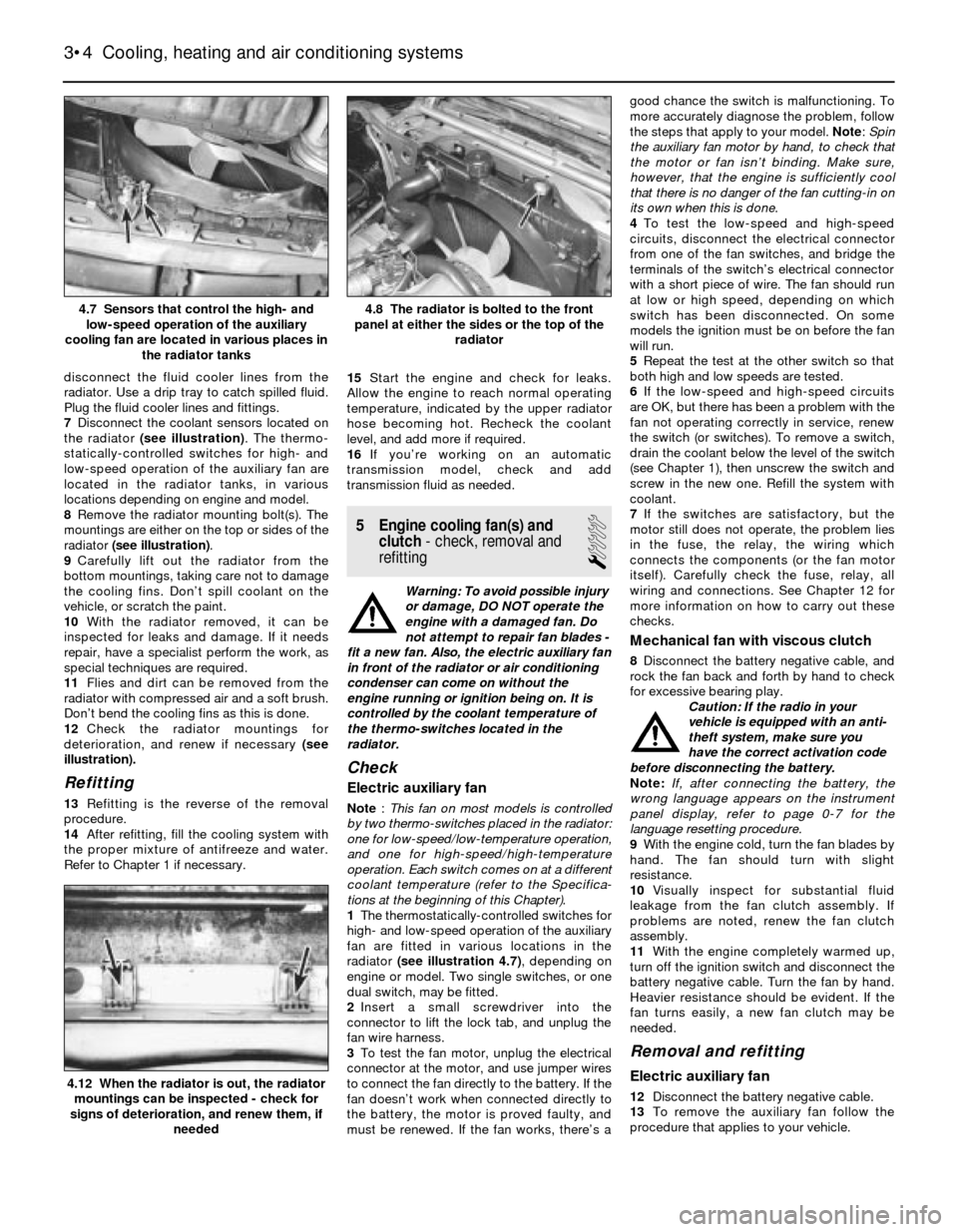
7Disconnect the coolant sensors located on
the radiator (see illustration). The thermo-
statically-controlled switches for high- and
low-speed operation of the auxiliary fan are
located in the radiator tanks, in various
locations depending on engine and model.
8Remove the radiator mounting bolt(s). The
mountings are either on the top or sides of the
radiator (see illustration).
9Carefully lift out the radiator from the
bottom mountings, taking care not to damage
the cooling fins. Don’t spill coolant on the
vehicle, or scratch the paint.
10With the radiator removed, it can be
inspected for leaks and damage. If it needs
repair, have a specialist perform the work, as
special techniques are required.
11Flies and dirt can be removed from the
radiator with compressed air and a soft brush.
Don’t bend the cooling fins as this is done.
12Check the radiator mountings for
deterioration, and renew if necessary (see
illustration).
Refitting
13Refitting is the reverse of the removal
procedure.
14After refitting, fill the cooling system with
the proper mixture of antifreeze and water.
Refer to Chapter 1 if necessary.15Start the engine and check for leaks.
Allow the engine to reach normal operating
temperature, indicated by the upper radiator
hose becoming hot. Recheck the coolant
level, and add more if required.
16If you’re working on an automatic
transmission model, check and add
transmission fluid as needed.
5 Engine cooling fan(s) and
clutch- check, removal and
refitting
1
Warning: To avoid possible injury
or damage, DO NOT operate the
engine with a damaged fan. Do
not attempt to repair fan blades -
fit a new fan. Also, the electric auxiliary fan
in front of the radiator or air conditioning
condenser can come on without the
engine running or ignition being on. It is
controlled by the coolant temperature of
the thermo-switches located in the
radiator.
Check
Electric auxiliary fan
Note: This fan on most models is controlled
by two thermo-switches placed in the radiator:
one for low-speed/low-temperature operation,
and one for high-speed/high-temperature
operation. Each switch comes on at a different
coolant temperature (refer to the Specifica-
tions at the beginning of this Chapter).
1The thermostatically-controlled switches for
high- and low-speed operation of the auxiliary
fan are fitted in various locations in the
radiator (see illustration 4.7), depending on
engine or model. Two single switches, or one
dual switch, may be fitted.
2Insert a small screwdriver into the
connector to lift the lock tab, and unplug the
fan wire harness.
3To test the fan motor, unplug the electrical
connector at the motor, and use jumper wires
to connect the fan directly to the battery. If the
fan doesn’t work when connected directly to
the battery, the motor is proved faulty, and
must be renewed. If the fan works, there’s agood chance the switch is malfunctioning. To
more accurately diagnose the problem, follow
the steps that apply to your model. Note: Spin
the auxiliary fan motor by hand, to check that
the motor or fan isn’t binding. Make sure,
however, that the engine is sufficiently cool
that there is no danger of the fan cutting-in on
its own when this is done.
4To test the low-speed and high-speed
circuits, disconnect the electrical connector
from one of the fan switches, and bridge the
terminals of the switch’s electrical connector
with a short piece of wire. The fan should run
at low or high speed, depending on which
switch has been disconnected. On some
models the ignition must be on before the fan
will run.
5Repeat the test at the other switch so that
both high and low speeds are tested.
6If the low-speed and high-speed circuits
are OK, but there has been a problem with the
fan not operating correctly in service, renew
the switch (or switches). To remove a switch,
drain the coolant below the level of the switch
(see Chapter 1), then unscrew the switch and
screw in the new one. Refill the system with
coolant.
7If the switches are satisfactory, but the
motor still does not operate, the problem lies
in the fuse, the relay, the wiring which
connects the components (or the fan motor
itself). Carefully check the fuse, relay, all
wiring and connections. See Chapter 12 for
more information on how to carry out these
checks.
Mechanical fan with viscous clutch
8Disconnect the battery negative cable, and
rock the fan back and forth by hand to check
for excessive bearing play.
Caution: If the radio in your
vehicle is equipped with an anti-
theft system, make sure you
have the correct activation code
before disconnecting the battery.
Note: If, after connecting the battery, the
wrong language appears on the instrument
panel display, refer to page 0-7 for the
language resetting procedure.
9With the engine cold, turn the fan blades by
hand. The fan should turn with slight
resistance.
10Visually inspect for substantial fluid
leakage from the fan clutch assembly. If
problems are noted, renew the fan clutch
assembly.
11With the engine completely warmed up,
turn off the ignition switch and disconnect the
battery negative cable. Turn the fan by hand.
Heavier resistance should be evident. If the
fan turns easily, a new fan clutch may be
needed.
Removal and refitting
Electric auxiliary fan
12Disconnect the battery negative cable.
13To remove the auxiliary fan follow the
procedure that applies to your vehicle.
3•4 Cooling, heating and air conditioning systems
4.12 When the radiator is out, the radiator
mountings can be inspected - check for
signs of deterioration, and renew them, if
needed
4.8 The radiator is bolted to the front
panel at either the sides or the top of the
radiator4.7 Sensors that control the high- and
low-speed operation of the auxiliary
cooling fan are located in various places in
the radiator tanks
Page 83 of 228
3-Series models
14Remove the radiator grille assembly (see
Chapter 11).
15Unbolt and remove the fan bracket and
shroud assembly from the radiator (see
Section 5).
16Remove the radiator (see Section 4).
17Unbolt the air conditioning condenser
mounting bolts, where applicable. Do not
remove the condenser or disconnect any
refrigerant lines from the condenser.
18Carefully pull the condenser back towards
the engine, slightly, to gain access to lift the
auxiliary fan.
19Disconnect the fan motor electrical
connection and remove the auxiliary fan.
20Refitting is the reverse of removal.
5-Series models
21Remove the screws and trim panel in front
of the radiator.
22Unbolt the fan assembly from the
condenser mounting points.
23Disconnect the fan electrical connector.
24Remove the fan and housing from the car,
being careful not to damage the air
conditioning condenser (when applicable)
while removing the fan.
25Refitting is the reverse of removal.
Mechanical fan with viscous clutch
26Disconnect the battery negative cable.
Remove the fan shroud mounting screws or
plastic fasteners, and detach the shroud (see
Section 4).
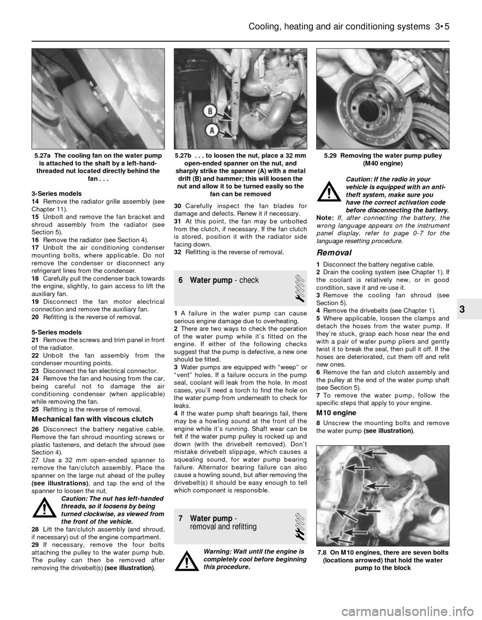
27 Use a 32 mm open-ended spanner to
remove the fan/clutch assembly. Place the
spanner on the large nut ahead of the pulley
(see illustrations), and tap the end of the
spanner to loosen the nut.
Caution: The nut has left-handed
threads, so it loosens by being
turned clockwise, as viewed from
the front of the vehicle.
28Lift the fan/clutch assembly (and shroud,
if necessary) out of the engine compartment.
29If necessary, remove the four bolts
attaching the pulley to the water pump hub.
The pulley can then be removed after
removing the drivebelt(s) (see illustration).30Carefully inspect the fan blades for
damage and defects. Renew it if necessary.
31At this point, the fan may be unbolted
from the clutch, if necessary. If the fan clutch
is stored, position it with the radiator side
facing down.
32Refitting is the reverse of removal.
6 Water pump- check
1
1A failure in the water pump can cause
serious engine damage due to overheating.
2There are two ways to check the operation
of the water pump while it’s fitted on the
engine. If either of the following checks
suggest that the pump is defective, a new one
should be fitted.
3Water pumps are equipped with “weep” or
“vent” holes. If a failure occurs in the pump
seal, coolant will leak from the hole. In most
cases, you’ll need a torch to find the hole on
the water pump from underneath to check for
leaks.
4If the water pump shaft bearings fail, there
may be a howling sound at the front of the
engine while it’s running. Shaft wear can be
felt if the water pump pulley is rocked up and
down (with the drivebelt removed). Don’t
mistake drivebelt slippage, which causes a
squealing sound, for water pump bearing
failure. Alternator bearing failure can also
cause a howling sound, but after removing the
drivebelt(s) it should be easy enough to tell
which component is responsible.
7 Water pump-
removal and refitting
2
Warning: Wait until the engine is
completely cool before beginning
this procedure.Caution: If the radio in your
vehicle is equipped with an anti-
theft system, make sure you
have the correct activation code
before disconnecting the battery.
Note: If, after connecting the battery, the
wrong language appears on the instrument
panel display, refer to page 0-7 for the
language resetting procedure.
Removal
1Disconnect the battery negative cable.
2Drain the cooling system (see Chapter 1). If
the coolant is relatively new, or in good
condition, save it and re-use it.
3Remove the cooling fan shroud (see
Section 5).
4Remove the drivebelts (see Chapter 1).
5Where applicable, loosen the clamps and
detach the hoses from the water pump. If
they’re stuck, grasp each hose near the end
with a pair of water pump pliers and gently
twist it to break the seal, then pull it off. If the
hoses are deteriorated, cut them off and refit
new ones.
6Remove the fan and clutch assembly and
the pulley at the end of the water pump shaft
(see Section 5).
7To remove the water pump, follow the
specific steps that apply to your engine.
M10 engine
8Unscrew the mounting bolts and remove
the water pump (see illustration).
Cooling, heating and air conditioning systems 3•5
5.29 Removing the water pump pulley
(M40 engine)5.27b . . . to loosen the nut, place a 32 mm
open-ended spanner on the nut, and
sharply strike the spanner (A) with a metal
drift (B) and hammer; this will loosen the
nut and allow it to be turned easily so the
fan can be removed5.27a The cooling fan on the water pump
is attached to the shaft by a left-hand-
threaded nut located directly behind the
fan . . .
7.8 On M10 engines, there are seven bolts
(locations arrowed) that hold the water
pump to the block
3
Page 84 of 228
M20 engine
9Remove the distributor cap and HT leads,
ignition rotor and dust shield (see Chapter 1).
10Where applicable, remove the timing
sensor (see Chapter 5).
11Remove the timing belt upper cover (see
Chapter 2A).
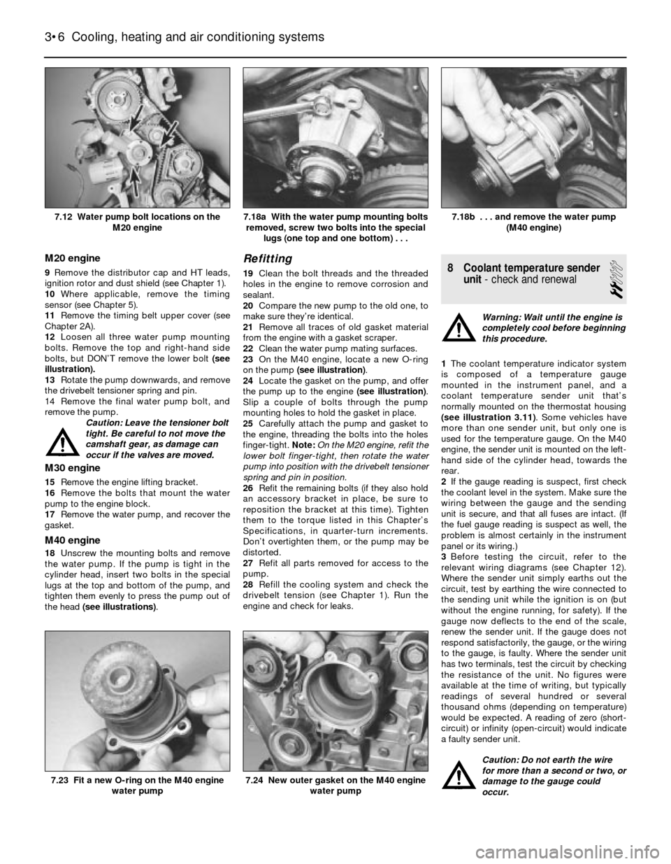
12Loosen all three water pump mounting
bolts. Remove the top and right-hand side
bolts, but DON’T remove the lower bolt (see
illustration).
13Rotate the pump downwards, and remove
the drivebelt tensioner spring and pin.
14 Remove the final water pump bolt, and
remove the pump.
Caution: Leave the tensioner bolt
tight. Be careful to not move the
camshaft gear, as damage can
occur if the valves are moved.
M30 engine
15Remove the engine lifting bracket.
16Remove the bolts that mount the water
pump to the engine block.
17Remove the water pump, and recover the
gasket.
M40 engine
18Unscrew the mounting bolts and remove
the water pump. If the pump is tight in the
cylinder head, insert two bolts in the special
lugs at the top and bottom of the pump, and
tighten them evenly to press the pump out of
the head (see illustrations).
Refitting
19Clean the bolt threads and the threaded
holes in the engine to remove corrosion and
sealant.
20Compare the new pump to the old one, to
make sure they’re identical.
21Remove all traces of old gasket material
from the engine with a gasket scraper.
22Clean the water pump mating surfaces.
23On the M40 engine, locate a new O-ring
on the pump (see illustration).
24Locate the gasket on the pump, and offer
the pump up to the engine (see illustration).
Slip a couple of bolts through the pump
mounting holes to hold the gasket in place.
25Carefully attach the pump and gasket to
the engine, threading the bolts into the holes
finger-tight.Note:On the M20 engine, refit the
lower bolt finger-tight, then rotate the water
pump into position with the drivebelt tensioner
spring and pin in position.
26Refit the remaining bolts (if they also hold
an accessory bracket in place, be sure to
reposition the bracket at this time). Tighten
them to the torque listed in this Chapter’s
Specifications, in quarter-turn increments.
Don’t overtighten them, or the pump may be
distorted.
27Refit all parts removed for access to the
pump.
28Refill the cooling system and check the
drivebelt tension (see Chapter 1). Run the
engine and check for leaks.8 Coolant temperature sender
unit- check and renewal
2
Warning: Wait until the engine is
completely cool before beginning
this procedure.
1The coolant temperature indicator system
is composed of a temperature gauge
mounted in the instrument panel, and a
coolant temperature sender unit that’s
normally mounted on the thermostat housing
(see illustration 3.11). Some vehicles have
more than one sender unit, but only one is
used for the temperature gauge. On the M40
engine, the sender unit is mounted on the left-
hand side of the cylinder head, towards the
rear.
2If the gauge reading is suspect, first check
the coolant level in the system. Make sure the
wiring between the gauge and the sending
unit is secure, and that all fuses are intact. (If
the fuel gauge reading is suspect as well, the
problem is almost certainly in the instrument
panel or its wiring.)
3Before testing the circuit, refer to the
relevant wiring diagrams (see Chapter 12).
Where the sender unit simply earths out the
circuit, test by earthing the wire connected to
the sending unit while the ignition is on (but
without the engine running, for safety). If the
gauge now deflects to the end of the scale,
renew the sender unit. If the gauge does not
respond satisfactorily, the gauge, or the wiring
to the gauge, is faulty. Where the sender unit
has two terminals, test the circuit by checking
the resistance of the unit. No figures were
available at the time of writing, but typically
readings of several hundred or several
thousand ohms (depending on temperature)
would be expected. A reading of zero (short-
circuit) or infinity (open-circuit) would indicate
a faulty sender unit.
Caution: Do not earth the wire
for more than a second or two, or
damage to the gauge could
occur.
3•6 Cooling, heating and air conditioning systems
7.24 New outer gasket on the M40 engine
water pump7.23 Fit a new O-ring on the M40 engine
water pump
7.18b . . . and remove the water pump
(M40 engine)7.18a With the water pump mounting bolts
removed, screw two bolts into the special
lugs (one top and one bottom) . . .7.12 Water pump bolt locations on the
M20 engine
Page 85 of 228
4If a new sender unit is to be fitted, make
sure the engine is completely cool. There will
be some coolant loss when the unit is
unscrewed, so be prepared to catch it, or
have the new unit ready to fit immediately the
old one is removed. Disconnect the wiring,
then unscrew the old unit from the engine,
and fit the new one. Use sealant on the
threads. Reconnect the wiring, and check the
coolant level on completion.
9 Heater and air conditioning
blower motor- removal,
testing and refitting
1
Removal
Note: The 3-Series models covered by this
manual have always used a single blower
motor for ventilation, heating and air
conditioning. “Old-shape” (E28) 5-Series
models use two separate blower motors: one
for ventilation and heating, and another for air
conditioning. “New-shape” (E34) 5-Series
models have a single blower motor, like the 3-
Series. The removal and refitting of the single
blower motor, and the old-shape 5-Series
vent/heat motor, is described below. The
removal and refitting of the old-shape 5-Series
air conditioning blower motor is described in
Section 14 of this Chapter.
Caution: If the radio in your
vehicle is equipped with an anti-
theft system, make sure you have
the correct activation code
before disconnecting the battery.
Note: If, after connecting the battery, the
wrong language appears on the instrument
panel display, refer to page 0-7 for the
language resetting procedure.
1Disconnect the battery negative cable.
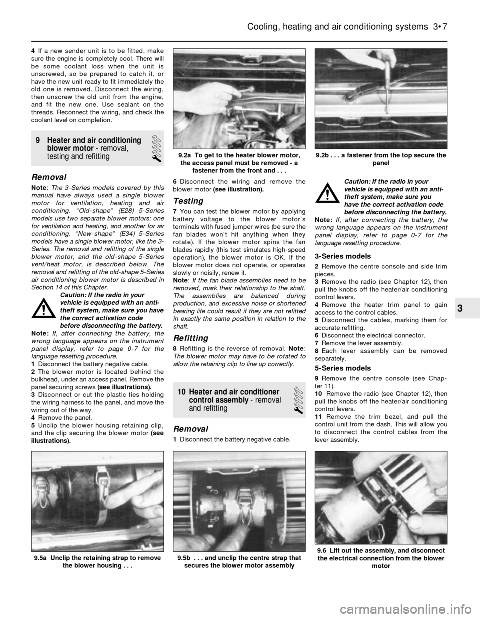
2The blower motor is located behind the
bulkhead, under an access panel. Remove the
panel securing screws (see illustrations).
3Disconnect or cut the plastic ties holding
the wiring harness to the panel, and move the
wiring out of the way.
4Remove the panel.
5Unclip the blower housing retaining clip,
and the clip securing the blower motor (see
illustrations).6Disconnect the wiring and remove the
blower motor (see illustration).
Testing
7You can test the blower motor by applying
battery voltage to the blower motor’s
terminals with fused jumper wires (be sure the
fan blades won’t hit anything when they
rotate). If the blower motor spins the fan
blades rapidly (this test simulates high-speed
operation), the blower motor is OK. If the
blower motor does not operate, or operates
slowly or noisily, renew it.
Note: If the fan blade assemblies need to be
removed, mark their relationship to the shaft.
The assemblies are balanced during
production, and excessive noise or shortened
bearing life could result if they are not refitted
in exactly the same position in relation to the
shaft.
Refitting
8Refitting is the reverse of removal. Note:
The blower motor may have to be rotated to
allow the retaining clip to line up correctly.
10 Heater and air conditioner
control assembly- removal
and refitting
1
Removal
1Disconnect the battery negative cable. Caution: If the radio in your
vehicle is equipped with an anti-
theft system, make sure you
have the correct activation code
before disconnecting the battery.
Note: If, after connecting the battery, the
wrong language appears on the instrument
panel display, refer to page 0-7 for the
language resetting procedure.
3-Series models
2Remove the centre console and side trim
pieces.
3Remove the radio (see Chapter 12), then
pull the knobs off the heater/air conditioning
control levers.
4Remove the heater trim panel to gain
access to the control cables.
5Disconnect the cables, marking them for
accurate refitting.
6Disconnect the electrical connector.
7Remove the lever assembly.
8Each lever assembly can be removed
separately.
5-Series models
9Remove the centre console (see Chap-
ter 11).
10Remove the radio (see Chapter 12), then
pull the knobs off the heater/air conditioning
control levers.
11Remove the trim bezel, and pull the
control unit from the dash. This will allow you
to disconnect the control cables from the
lever assembly.
Cooling, heating and air conditioning systems 3•7
9.5a Unclip the retaining strap to remove
the blower housing . . .
9.2b . . . a fastener from the top secure the
panel9.2a To get to the heater blower motor,
the access panel must be removed - a
fastener from the front and . . .
9.6 Lift out the assembly, and disconnect
the electrical connection from the blower
motor9.5b . . . and unclip the centre strap that
secures the blower motor assembly
3
Page 86 of 228
12Disconnect the cables from the clips
securing them to the lever assembly, marking
them for accurate refitting.
13Disconnect the electrical connection from
the control assembly.
14Remove the screws attaching the bezel to
the control assembly, and remove the control
assembly.
Refitting
15Refitting is the reverse of the removal
procedure.
11 Heater matrix-
removal and refitting
1
Caution: If the radio in your
vehicle is equipped with an anti-
theft system, make sure you
have the correct activation code
before disconnecting the battery.
Note: If, after connecting the battery, the
wrong language appears on the instrument
panel display, refer to page 0-7 for the
language resetting procedure.
1Disconnect the battery negative cable.
2Drain the cooling system (see Chapter 1).
3Remove the centre console (see Chap-
ter 11). Spread an old blanket over the front
carpeting; this will prevent stains if any
residual coolant spills.
Removal
3-Series models
4Remove the left-hand side heater ducting,
and set it aside.
5Remove the heater valve clamp.
6Remove the screws and detach the flange
where the two coolant lines enter the heater
matrix case. Be careful; some coolant may
spill.
7Remove the two screws holding the heater
matrix case to the heater main assembly.
8Slide the heater matrix out of the mounting.
Be careful not to spill any of the remaining
coolant in the heater matrix when removing it.
5-Series models
9Disconnect the temperature sensor
electrical connectors.
10Disconnect the straps holding the wiring
to the case, and set the wiring out of the way.
11Unfasten the cover fasteners.
12Remove the screws holding the cover in
place, then remove the cover.
13Disconnect all heater pipe connections
attached to the heater matrix. Be careful;
some coolant may spill.
14Lifting on the right side of the heater
matrix first, remove the heater matrix.
Refitting
Note: Always use new O-rings when attaching
the coolant lines to the heater matrix.15Refitting is the reverse of removal. Refill
the cooling system (see Chapter 1), then run
the engine with the heater on, and check for
correct operation and leaks.
12 Air conditioning system-
precautions and maintenance
1
Precautions
Warning: The air conditioning
system is under high pressure.
DO NOT loosen any hose or line
fittings, or remove any
components, until after the system has
been discharged. Air conditioning
refrigerant should be properly discharged
by a qualified refrigeration engineer. The
refrigerant used in the system must not be
allowed into contact with your skin or
eyes, or there is a risk of frostbite. Should
the refrigerant come into contact with a
naked flame, a poisonous gas will be
produced. Smoking in the presence of
refrigerant is therefore highly dangerous,
particularly if refrigerant vapour is inhaled
through a lighted cigarette. The refrigerant
is heavier than air, and it may cause
suffocation if discharged in an enclosed
space such as a domestic garage.
Finally, uncontrolled release of the
refrigerant causes environmental damage,
by contributing to the “greenhouse
effect”.
Maintenance
1The following maintenance checks should
be performed on a regular basis to ensure the
air conditioner continues to operate at peak
efficiency:
a) Check the drivebelt. If it’s worn or
deteriorated, renew it (see Chapter 1).
b) Check the system hoses. Look for cracks,
bubbles, hard spots and deterioration.
Inspect the hoses and all fittings for oil
bubbles and seepage. If there’s any
evidence of wear, damage or leaks, have
new hose(s) fitted.
c) Inspect the condenser fins for leaves, flies
and other debris. Use a “fin comb” or
compressed air to clean the condenser.
d) Make sure the system has the correct
refrigerant charge, as described below.
2It’s a good idea to operate the system for
about 10 minutes at least once a month,
particularly during the winter. Long-term non-
use can cause hardening, and subsequent
failure, of the seals.
3Because of the complexity of the air
conditioning system and the special
equipment necessary to service it, in-depth
fault diagnosis and repair procedures are not
included in this manual. However, simple
checks and component renewal procedures
are provided in this Chapter.
4The most common cause of poor cooling issimply a low system refrigerant charge. If a
noticeable loss of cool air output occurs, the
following quick check may help you determine
if the refrigerant level is low.
5Warm the engine up to normal operating
temperature.
6Set the air conditioning temperature
selector at the coldest setting, and put the
blower at the highest setting. Open the doors
(to make sure the air conditioning system
doesn’t switch off as soon as it cools the
passenger compartment).
7With the compressor engaged - the
compressor clutch will make an audible click,
and the centre of the clutch will rotate - feel
the tube located adjacent to the right front
frame rail, near the radiator.
8If a significant temperature drop is noticed,
the refrigerant level is probably OK.
9If the inlet line has frost accumulation, or
feels cooler than the receiver-drier surface,
the refrigerant charge is low. Recharging the
system should be carried out by a qualified
refrigeration engineer.
13 Air conditioning compressor
- removal and refitting
5
Warning: Due to the potential
dangers associated with the
system, you are strongly advised
to have any work on the air
conditioning system carried out by a BMW
dealer or air conditioning specialist. At the
very least, DO NOT dismantle any part of
the system (hoses, compressor, line
fittings, etc.) until after the system has
been discharged by a qualified engineer.
Refer to the precautions given at the start
of Section 12.
Note: If a new compressor is fitted, the
receiver-drier (see Section 16) should also be
renewed.
Removal
1Have the air conditioning system
discharged (see Warning above).
2Disconnect the battery negative cable.
Caution: If the radio in your
vehicle is equipped with an anti-
theft system, make sure you
have the correct activation code
before disconnecting the battery.
Note: If, after connecting the battery, the
wrong language appears on the instrument
panel display, refer to page 0-7 for the
language resetting procedure.
3Disconnect the compressor clutch wiring
harness.
4Remove the drivebelt (see Chapter 1).
5Disconnect the refrigerant lines from the
rear of the compressor. Plug the open fittings
to prevent entry of dirt and moisture.
6Unbolt the compressor from the mounting
3•8 Cooling, heating and air conditioning systems
Page 87 of 228
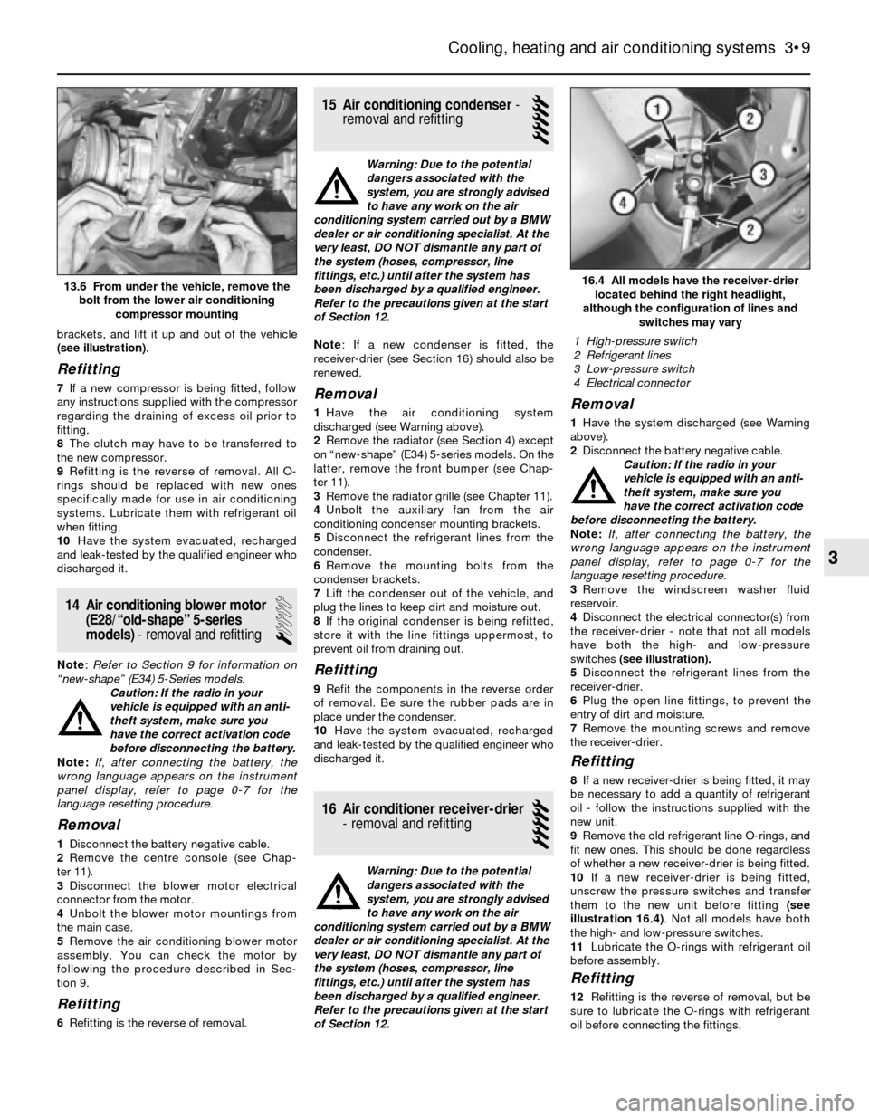
brackets, and lift it up and out of the vehicle
(see illustration).
Refitting
7If a new compressor is being fitted, follow
any instructions supplied with the compressor
regarding the draining of excess oil prior to
fitting.
8The clutch may have to be transferred to
the new compressor.
9Refitting is the reverse of removal. All O-
rings should be replaced with new ones
specifically made for use in air conditioning
systems. Lubricate them with refrigerant oil
when fitting.
10Have the system evacuated, recharged
and leak-tested by the qualified engineer who
discharged it.
14 Air conditioning blower motor
(E28/“old-shape” 5-series
models)- removal and refitting
1
Note: Refer to Section 9 for information on
“new-shape” (E34) 5-Series models.
Caution: If the radio in your
vehicle is equipped with an anti-
theft system, make sure you
have the correct activation code
before disconnecting the battery.
Note: If, after connecting the battery, the
wrong language appears on the instrument
panel display, refer to page 0-7 for the
language resetting procedure.
Removal
1Disconnect the battery negative cable.
2Remove the centre console (see Chap-
ter 11).
3Disconnect the blower motor electrical
connector from the motor.
4Unbolt the blower motor mountings from
the main case.
5Remove the air conditioning blower motor
assembly. You can check the motor by
following the procedure described in Sec-
tion 9.
Refitting
6Refitting is the reverse of removal.
15 Air conditioning condenser-
removal and refitting
5
Warning: Due to the potential
dangers associated with the
system, you are strongly advised
to have any work on the air
conditioning system carried out by a BMW
dealer or air conditioning specialist. At the
very least, DO NOT dismantle any part of
the system (hoses, compressor, line
fittings, etc.) until after the system has
been discharged by a qualified engineer.
Refer to the precautions given at the start
of Section 12.
Note: If a new condenser is fitted, the
receiver-drier (see Section 16) should also be
renewed.
Removal
1Have the air conditioning system
discharged (see Warning above).
2Remove the radiator (see Section 4) except
on “new-shape” (E34) 5-series models. On the
latter, remove the front bumper (see Chap-
ter 11).
3Remove the radiator grille (see Chapter 11).
4Unbolt the auxiliary fan from the air
conditioning condenser mounting brackets.
5Disconnect the refrigerant lines from the
condenser.
6Remove the mounting bolts from the
condenser brackets.
7Lift the condenser out of the vehicle, and
plug the lines to keep dirt and moisture out.
8If the original condenser is being refitted,
store it with the line fittings uppermost, to
prevent oil from draining out.
Refitting
9Refit the components in the reverse order
of removal. Be sure the rubber pads are in
place under the condenser.
10Have the system evacuated, recharged
and leak-tested by the qualified engineer who
discharged it.
16 Air conditioner receiver-drier
- removal and refitting
5
Warning: Due to the potential
dangers associated with the
system, you are strongly advised
to have any work on the air
conditioning system carried out by a BMW
dealer or air conditioning specialist. At the
very least, DO NOT dismantle any part of
the system (hoses, compressor, line
fittings, etc.) until after the system has
been discharged by a qualified engineer.
Refer to the precautions given at the start
of Section 12.
Removal
1Have the system discharged (see Warning
above).
2Disconnect the battery negative cable.
Caution: If the radio in your
vehicle is equipped with an anti-
theft system, make sure you
have the correct activation code
before disconnecting the battery.
Note: If, after connecting the battery, the
wrong language appears on the instrument
panel display, refer to page 0-7 for the
language resetting procedure.
3Remove the windscreen washer fluid
reservoir.
4Disconnect the electrical connector(s) from
the receiver-drier - note that not all models
have both the high- and low-pressure
switches (see illustration).
5Disconnect the refrigerant lines from the
receiver-drier.
6Plug the open line fittings, to prevent the
entry of dirt and moisture.
7Remove the mounting screws and remove
the receiver-drier.
Refitting
8If a new receiver-drier is being fitted, it may
be necessary to add a quantity of refrigerant
oil - follow the instructions supplied with the
new unit.
9Remove the old refrigerant line O-rings, and
fit new ones. This should be done regardless
of whether a new receiver-drier is being fitted.
10If a new receiver-drier is being fitted,
unscrew the pressure switches and transfer
them to the new unit before fitting (see
illustration 16.4). Not all models have both
the high- and low-pressure switches.
11Lubricate the O-rings with refrigerant oil
before assembly.
Refitting
12Refitting is the reverse of removal, but be
sure to lubricate the O-rings with refrigerant
oil before connecting the fittings.
Cooling, heating and air conditioning systems 3•9
16.4 All models have the receiver-drier
located behind the right headlight,
although the configuration of lines and
switches may vary
3
13.6 From under the vehicle, remove the
bolt from the lower air conditioning
compressor mounting
1 High-pressure switch
2 Refrigerant lines
3 Low-pressure switch
4 Electrical connector
Page 88 of 228
13Have the system evacuated, recharged
and leak-tested by the qualified engineer who
discharged it.
17 Evaporator matrix-
removal and refitting
5
Warning: Due to the potential
dangers associated with the
system, you are strongly advised
to have any work on the air conditioning
system carried out by a BMW dealer or airconditioning specialist. At the very least,
DO NOT dismantle any part of the system
(hoses, compressor, line fittings, etc.) until
after the system has been discharged by a
qualified engineer. Refer to the pre-
cautions given at the start of Section 12.
Removal
1Have the air conditioning system
discharged (see Warning above).
2Remove the trim panel on the sides of the
centre console (see Chapter 11)
3Disconnect the electrical lead and remove
the evaporator sensor.4Remove the evaporator cover, exposing the
refrigerant lines.
5Disconnect the refrigerant lines from the
evaporator matrix.
6Remove the evaporator matrix from the
case.Refitting
7Refitting is the reverse procedure of the
removal.
8Have the system evacuated, recharged and
leak-tested by the qualified engineer who
discharged it.
3•10 Cooling, heating and air conditioning systems
Page 95 of 228
correct resistance. On L-Jetronic and early
Motronic systems, follow the table below. On
later Motronic systems, connect the
ohmmeter probes onto the fuel level sender
unit terminals that correspond to pins 1 and 3
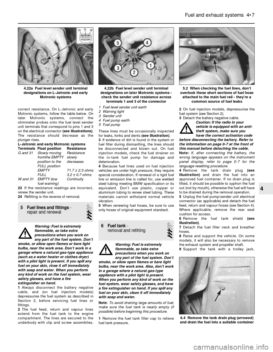
on the electrical connector (see illustrations).
The resistance should decrease as the
plunger rises.
L-Jetronic and early Motronic systems
Terminals Float position Resistance
G and 31 Slowly moving Resistance
fromthe EMPTY slowly
position to the decreases
FULL position
EMPTY 71.7 ± 2.3 ohms
FULL 3.2 ± 0.7 ohms
W and 31 EMPTY (low Continuity
fuel warning)
23If the resistance readings are incorrect,
renew the sender unit.
24Refitting is the reverse of removal.
5 Fuel lines and fittings-
repair and renewal
3
Warning: Fuel is extremely
flammable, so take extra
precautions when you work on
any part of the fuel system. Don’t
smoke, or allow open flames or bare light
bulbs, near the work area. Don’t work in a
garage where a natural gas-type appliance
(such as a water heater or clothes dryer)
with a pilot light is present. If you spill any
fuel on your skin, rinse it off immediately
with soap and water. When you perform
any kind of work on the fuel system, wear
safety glasses, and have a fire
extinguisher on hand.
1Always disconnect the battery negative
cable, and (on fuel injection models)
depressurise the fuel system as described in
Section 2, before servicing fuel lines or
fittings.
2The fuel feed, return and vapour lines
extend from the fuel tank to the engine
compartment. The lines are secured to the
underbody with clip and screw assemblies.These lines must be occasionally inspected
for leaks, kinks and dents (see illustration).
3If evidence of dirt is found in the system or
fuel filter during dismantling, the lines should
be disconnected and blown out. On fuel
injection models, check the fuel strainer on
the in-tank fuel pump for damage and
deterioration.
4Because fuel lines used on fuel injection
vehicles are under high pressure, they require
special consideration. If renewal of a rigid fuel
line or emission line is called for, use welded
steel tubing meeting BMW specification or its
equivalent. Don’t use plastic, copper or
aluminium tubing to renew steel tubing. These
materials cannot withstand normal vehicle
vibration.
5When renewing fuel hoses, be sure to use
only hoses of original-equipment standard.6 Fuel tank-
removal and refitting
3
Warning: Fuel is extremely
flammable, so take extra
precautions when you work on
any part of the fuel system. Don’t
smoke, or allow open flames or bare light
bulbs, near the work area. Also, don’t work
in a garage where a natural gas-type
appliance with a pilot light is present.
When you perform any kind of work on the
fuel system, wear safety glasses, and have
a fire extinguisher on hand. If you spill any
fuel on your skin, clean it off immediately
with soap and water.
Note: To avoid draining large amounts of fuel,
make sure the fuel tank is nearly empty (if
possible) before beginning this procedure.
1Remove the fuel tank filler cap to relieve
fuel tank pressure.2On fuel injection models, depressurise the
fuel system (see Section 2).
3Detach the battery negative cable.
Caution: If the radio in your
vehicle is equipped with an anti-
theft system, make sure you
have the correct activation code
before disconnecting the battery. Refer to
the information on page 0-7 at the front of
this manual before detaching the cable.
Note: If, after connecting the battery, the
wrong language appears on the instrument
panel display, refer to page 0-7 for the
language resetting procedure.
4Remove the tank drain plug (see
illustration)and drain the fuel into an
approved fuel container. If no drain plug is
fitted, it should be possible to syphon the fuel
out (not by mouth), otherwise the fuel will have
to be drained during the removal operation.
5Unplug the fuel pump/sender unit electrical
connector (as applicable) and detach the fuel
feed, return and vapour hoses (see Section 4).
Where applicable, remove the rear seat
cushion for access.
6Remove the fuel tank shield (see
illustration).
7Detach the fuel filler neck and breather
hoses.
8Raise and support the vehicle. On some
models, it will also be necessary to remove
the exhaust system and propeller shaft.
9Support the tank with a trolley jack.
Fuel and exhaust systems 4•7
4.22b Fuel level sender unit terminal
designations on later Motronic systems -
check the sender unit resistance across
terminals 1 and 3 of the connector
1 Fuel level sender unit earth
2 Warning light
3 Sender unit
4 Fuel pump earth
5 Fuel pump4.22a Fuel level sender unit terminal
designations on L-Jetronic and early
Motronic systems
6.4 Remove the tank drain plug (arrowed)
and drain the fuel into a suitable container
5.2 When checking the fuel lines, don’t
overlook these short sections of fuel hose
attached to the main fuel rail - they’re a
common source of fuel leaks
4
Page 98 of 228
Caution: If the radio in your
vehicle is equipped with an anti-
theft system, make sure you
have the correct activation code before
disconnecting the battery. Refer to the
information on page 0-7 at the front of this
manual before detaching the cable.
Note: If, after connecting the battery, the
wrong language appears on the instrument
panel display, refer to page 0-7 for the
language resetting procedure.
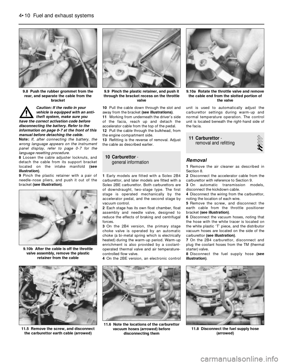
8Loosen the cable adjuster locknuts, and
detach the cable from its support bracket
located on the intake manifold (see
illustration).
9Pinch the plastic retainer with a pair of
needle-nose pliers, and push it out of the
bracket (see illustration).10Pull the cable down through the slot and
away from the bracket (see illustrations).
11Working from underneath the driver’s side
of the facia, reach up and detach the
accelerator cable from the top of the pedal.
12Pull the cable through the bulkhead, from
the engine compartment side.
13Refitting is the reverse of removal. Adjust
the cable as described earlier.
10 Carburettor-
general information
1Early models are fitted with a Solex 2B4
carburettor, and later models are fitted with a
Solex 2BE carburettor. Both carburettors are
of downdraught, two-stage type. The first
stage is operated mechanically by the
accelerator pedal, and the second stage by
vacuum control.
2Each stage has its own float chamber, float
assembly and needle valve, designed to
reduce the effects of braking and centrifugal
forces.
3On the 2B4 version, the primary stage
choke valve is operated by an automatic
choke (a bi-metal spring which is electrically
heated) during the warm-up period. Warm-up
enrichment is also provided by a coolant-
operated thermal valve and air temperature-
controlled flow valve.
4On the 2BE version, an electronic controlunit is used to automatically adjust the
carburettor settings during warm-up and
normal temperature operation. The control
unit is located beneath the right-hand side of
the facia.
11 Carburettor-
removal and refitting
2
Removal
1Remove the air cleaner as described in
Section 8.
2Disconnect the accelerator cable from the
carburettor with reference to Section 9.
3On automatic transmission models,
disconnect the kickdown cable.
4Disconnect the wiring from the carburettor,
noting the location of each wire.
5Remove the screw, and disconnect the
earth cable from the throttle positioner
bracket (see illustration).
6Disconnect the vacuum hoses, noting that
the hose with the white tracer is located on
the white plastic ‘T’ piece, and the distributor
vacuum hoses are located on the side of the
carburettor (see illustration).
7On the 2B4 carburettor, disconnect and
plug the coolant hoses from the TM (thermal
starter) valve.
8Disconnect the fuel supply hose (see
illustration).
4•10 Fuel and exhaust systems
11.8 Disconnect the fuel supply hose
(arrowed)11.6 Note the locations of the carburettor
vacuum hoses (arrowed) before
disconnecting them11.5 Remove the screw, and disconnect
the carburettor earth cable (arrowed)
9.10b After the cable is off the throttle
valve assembly, remove the plastic
retainer from the cable
9.10a Rotate the throttle valve and remove
the cable end from the slotted portion of
the valve9.9 Pinch the plastic retainer, and push it
through the bracket recess on the throttle
valve9.8 Push the rubber grommet from the
rear, and separate the cable from the
bracket
Page 102 of 228
Throttle positioner (2BE)
24Special tools are required to carry out a
comprehensive adjustment on the 2BE
carburettor. This work should therefore be left
to a BMW dealer.
13 Fuel injection -
general information
The fuel injection system is composed of
three basic sub-systems: fuel system, air
intake system and electronic control system.
Fuel system
An electric fuel pump, located inside the
fuel tank or beside the fuel tank, supplies fuel
under constant pressure to the fuel rail, which
distributes fuel evenly to all injectors. From
the fuel rail, fuel is injected into the intake
ports, just above the intake valves, by the fuel
injectors. The amount of fuel supplied by the
injectors is precisely controlled by an
Electronic Control Unit (ECU). An additional
injector, known as the cold start injector (L-
Jetronic and early Motronic systems only),
supplies extra fuel into the intake manifold for
starting. A pressure regulator controls system
pressure in relation to intake manifold
vacuum. A fuel filter between the fuel pump
and the fuel rail filters the fuel, to protect the
components of the system.
Air intake system
The air intake system consists of an air filter
housing, an airflow meter, a throttle body, the
intake manifold, and the associated ducting.
The airflow meter is an information-gathering
device for the ECU. These models are
equipped with the vane-type airflow meter. A
potentiometer measures intake airflow, and a
temperature sensor measures intake air
temperature. This information helps the ECU
determine the amount of fuel to be injected by
the injectors (injection duration). The throttle
plate inside the throttle body is controlled by
the driver. As the throttle plate opens, the
amount of air that can pass through the
system increases, so the potentiometer opens
further and the ECU signals the injectors to
increase the amount of fuel delivered to the
intake ports.
Electronic control system
The computer control system controls the
fuel system and other systems by means of
an Electronic Control Unit (ECU). The ECU
receives signals from a number of information
sensors which monitor such variables as
intake air volume, intake air temperature,
coolant temperature, engine rpm,
acceleration/deceleration, and exhaust
oxygen content. These signals help the ECU
determine the injection duration necessary for
the optimum air/fuel ratio. These sensors and
their corresponding ECU-controlled outputactuators are located throughout the engine
compartment. For further information
regarding the ECU and its relationship to the
engine electrical systems and ignition system,
refer to Chapters 5 and 6.
Either an L-Jetronic system or a Motronic
system is fitted. Later models have an
updated version of the original Motronic
system.
14 Fuel injection systems
L-Jetronic fuel injection system
The Bosch L-Jetronic fuel injection system
is used on most 3-Series models up to 1987,
and on most E28 (“old-shape”) 5-Series
models. It is an electronically-controlled fuel
injection system that utilises one solenoid-
operated fuel injector per cylinder. The system
is governed by an Electronic Control Unit
(ECU) which processes information sent by
various sensors, and in turn precisely
meters the fuel to the cylinders by
adjusting the amount of time that the injectors
are open.
An electric fuel pump delivers fuel under
high pressure to the injectors, through the fuel
feed line and an in-line filter. A pressure
regulator keeps fuel available at an optimum
pressure, allowing pressure to rise or fall
depending on engine speed and load. Any
excess fuel is returned to the fuel tank by a
separate line.
A sensor in the air intake duct constantly
measures the mass of the incoming air, and
the ECU adjusts the fuel mixture to provide an
optimum air/fuel ratio.
Other components incorporated in the
system are the throttle valve (which controls
airflow to the engine), the coolant temperature
sensor, the throttle position switch, idle
stabiliser valve (which bypasses air around
the throttle plate to control idle speed) and
associated relays and fuses.
Motronic fuel injection system
The Motronic system combines the fuel
control of the L-Jetronic fuel injection system
with the control of ignition timing, idle speed
and emissions into one control unit.
The fuel injection and idle speed control
functions are similar to those used on the L-
Jetronic system described above. For more
information on the Motronic system, see
Chapter 6.
An oxygen sensor is mounted in the
exhaust system on later models with a
catalytic converter. This sensor continually
reads the oxygen content of the exhaust gas.
The information is used by the ECU to adjust
the duration of injection, making it possible to
adjust the fuel mixture for optimum converter
efficiency and minimum emissions.
15 Fuel injection system-
check
2
Warning: Fuel is extremely
flammable, so take extra
precautions when you work on
any part of the fuel system. Don’t
smoke, or allow open flames or bare light
bulbs, near the work area. Don’t work in a
garage where a natural gas-type appliance
(such as a water heater or clothes dryer)
with a pilot light is present. If you spill any
fuel on your skin, rinse it off immediately
with soap and water. When you perform
any kind of work on the fuel system, wear
safety glasses, and have a fire
extinguisher on hand.
1Check the earth wire connections. Check
all wiring harness connectors that are related
to the system. Loose connectors and poor
earths can cause many problems that
resemble more serious malfunctions.
2Make sure the battery is fully charged, as
the control unit and sensors depend on an
accurate supply voltage in order to properly
meter the fuel.
3Check the air filter element - a dirty or
partially-blocked filter will severely impede
performance and economy (see Chapter 1).
4If a blown fuse is found, renew it and see if
it blows again. If it does, search for an earthed
wire in the harness related to the system.
5Check the air intake duct from the airflow
meter to the intake manifold for leaks. Intake
air leaks can cause a variety of problems. Also
check the condition of the vacuum hoses
connected to the intake manifold.
6Remove the air intake duct from the throttle
body, and check for dirt, carbon and other
residue build-up. If it’s dirty, clean it with
carburettor cleaner and a toothbrush.
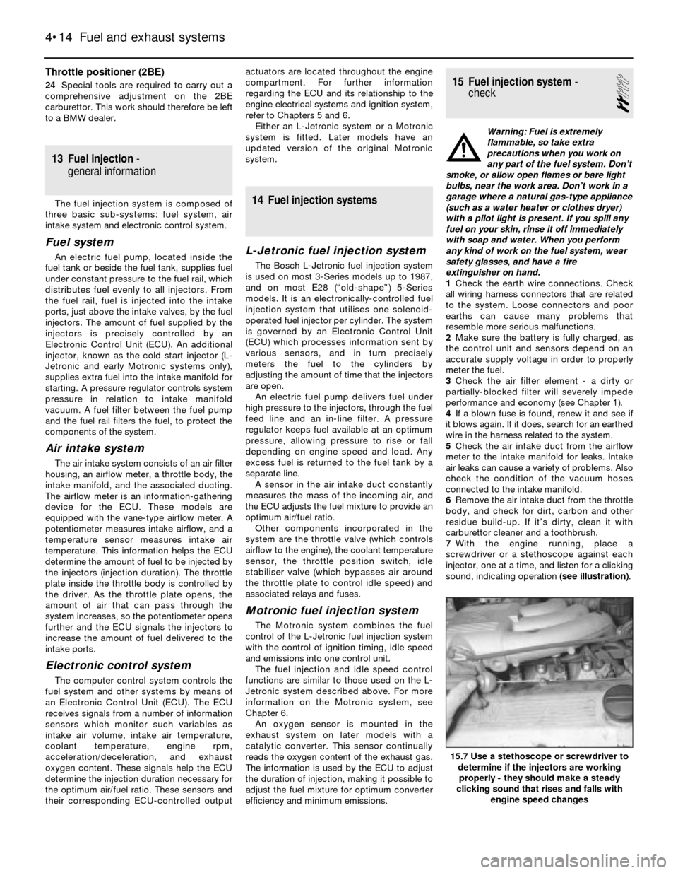
7With the engine running, place a
screwdriver or a stethoscope against each
injector, one at a time, and listen for a clicking
sound, indicating operation (see illustration).
4•14 Fuel and exhaust systems
15.7 Use a stethoscope or screwdriver to
determine if the injectors are working
properly - they should make a steady
clicking sound that rises and falls with
engine speed changes