BMW 5 SERIES 2001 E39 Basic handsfree retrokit for updating various mobile phones Instalation Instruction Manual
Manufacturer: BMW, Model Year: 2001, Model line: 5 SERIES, Model: BMW 5 SERIES 2001 E39Pages: 36, PDF Size: 1.5 MB
Page 11 of 36
EN/11Retrofit/Installation kit No. 65 90 0 028 873 84 64 25,805 (others see cover sheet)
Installation Instructions no. 01 29 0 029 541 01 29 0 029 544 Issue date: 04.2001
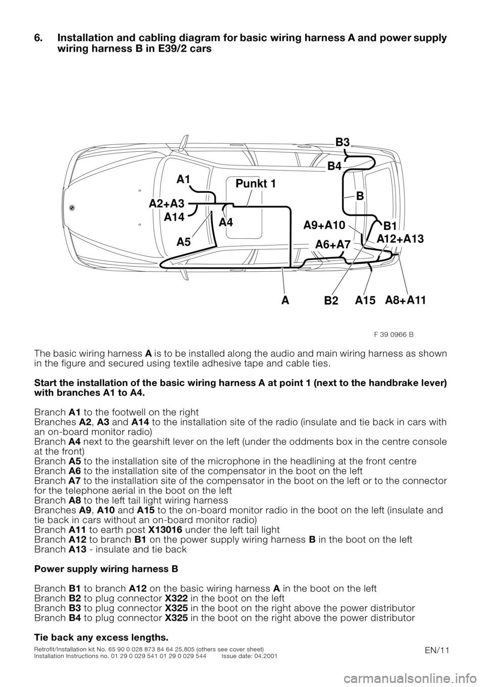
6. Installation and cabling diagram for basic wiring harness A and power supply
wiring harness B in E39/2 cars
0
The basic wiring harness A is to be installed along the audio and main wiring harness as shown
in the figure and secured using textile adhesive tape and cable ties.
Start the installation of the basic wiring harness A at point 1 (next to the handbrake lever)
with branches A1 to A4.
Branch A1 to the footwell on the right
Branches A2, A3 and A14 to the installation site of the radio (insulate and tie back in cars with
an on-board monitor radio)
Branch A4 next to the gearshift lever on the left (under the oddments box in the centre console
at the front)
Branch A5 to the installation site of the microphone in the headlining at the front centre
Branch A6 to the installation site of the compensator in the boot on the left
Branch A7 to the installation site of the compensator in the boot on the left or to the connector
for the telephone aerial in the boot on the left
Branch A8 to the left tail light wiring harness
Branches A9, A10 and A15 to the on-board monitor radio in the boot on the left (insulate and
tie back in cars without an on-board monitor radio)
Branch A11 to earth post X13016 under the left tail light
Branch A12 to branch B1 on the power supply wiring harness B in the boot on the left
Branch A13 - insulate and tie back
Power supply wiring harness B
Branch B1 to branch A12 on the basic wiring harness A in the boot on the left
Branch B2 to plug connector X322 in the boot on the left
Branch B3 to plug connector X325 in the boot on the right above the power distributor
Branch B4 to plug connector X325 in the boot on the right above the power distributor
Tie back any excess lengths.
A6+A7
A8+A11 A12+A13
A9+A10
A1
A2+A3
A3A4
A5
Punkt 1Punkt 1
B1
B
B4
B3
B2
A
A14
A15
F 39 0966 B
Page 12 of 36
EN/12Retrofit/Installation kit No. 65 90 0 028 873 84 64 25,805 (others see cover sheet)
Installation Instructions no. 01 29 0 029 541 01 29 0 029 544 Issue date: 04.2001
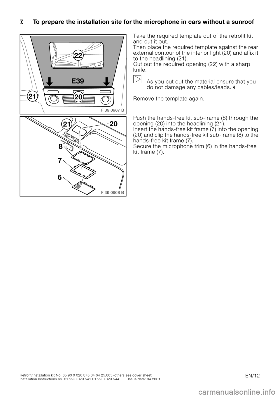
7. To prepare the installation site for the microphone in cars without a sunroof
0
00
Take the required template out of the retrofit kit
and cut it out.
Then place the required template against the rear
external contour of the interior light (20) and affix it
to the headlining (21).
Cut out the required opening (22) with a sharp
knife.
As you cut out the material ensure that you
do not damage any cables/leads.
"
Remove the template again.
0Push the hands-free kit sub-frame (8) through the
opening (20) into the headlining (21).
Insert the hands-free kit frame (7) into the opening
(20) and clip the hands-free kit sub-frame (8) to the
hands-free kit frame (7).
Secure the microphone trim (6) in the hands-free
kit frame (7).
.
20
22
21E39
F 39 0967 B
8
7
6
2120
F 39 0968 B
Page 13 of 36
EN/13Retrofit/Installation kit No. 65 90 0 028 873 84 64 25,805 (others see cover sheet)
Installation Instructions no. 01 29 0 029 541 01 29 0 029 544 Issue date: 04.2001
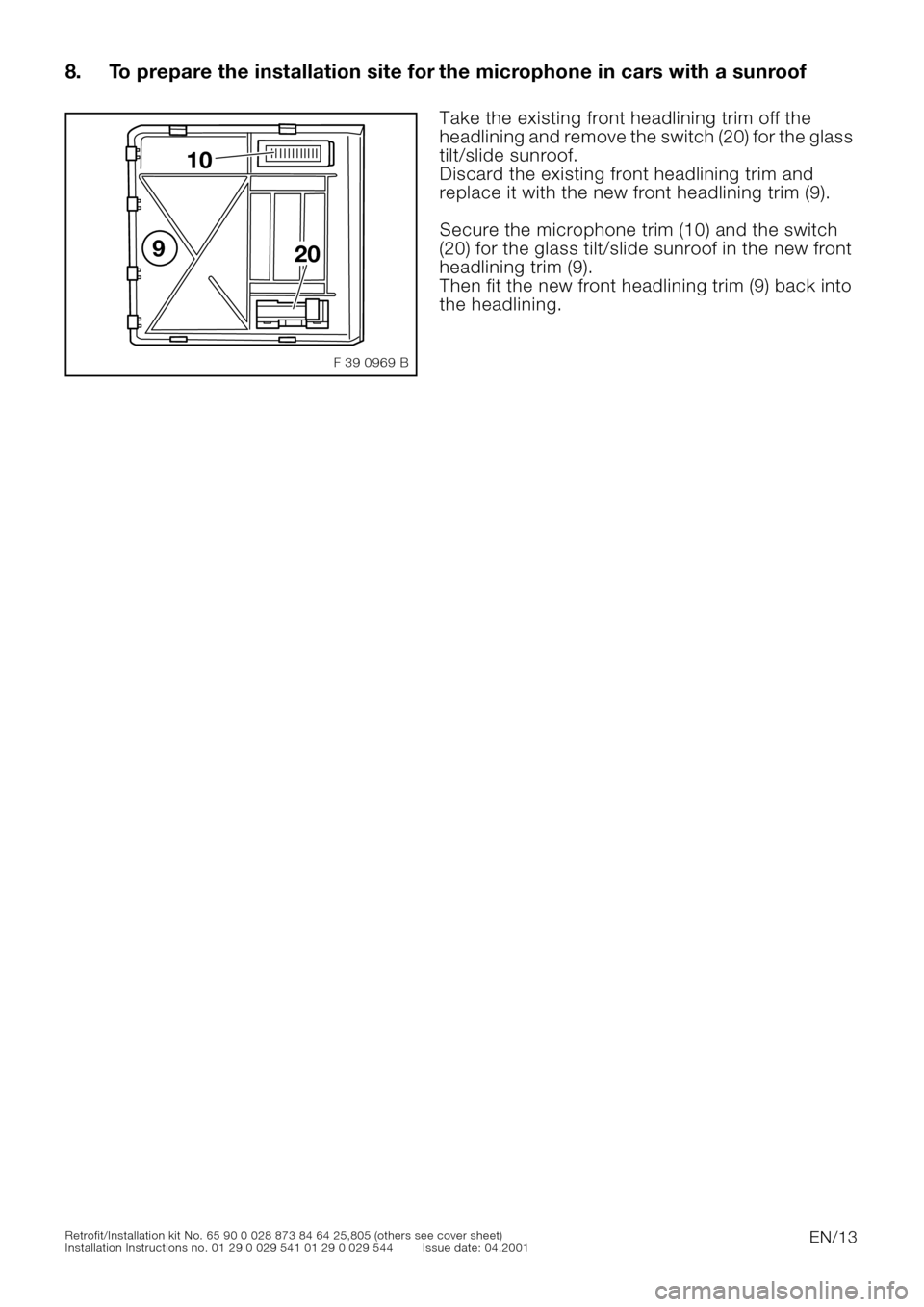
8. To prepare the installation site for the microphone in cars with a sunroof
0Take the existing front headlining trim off the
headlining and remove the switch (20) for the glass
tilt/slide sunroof.
Discard the existing front headlining trim and
replace it with the new front headlining trim (9).
Secure the microphone trim (10) and the switch
(20) for the glass tilt/slide sunroof in the new front
headlining trim (9).
Then fit the new front headlining trim (9) back into
the headlining.
10
920
F 39 0969 B
Page 14 of 36
EN/14Retrofit/Installation kit No. 65 90 0 028 873 84 64 25,805 (others see cover sheet)
Installation Instructions no. 01 29 0 029 541 01 29 0 029 544 Issue date: 04.2001
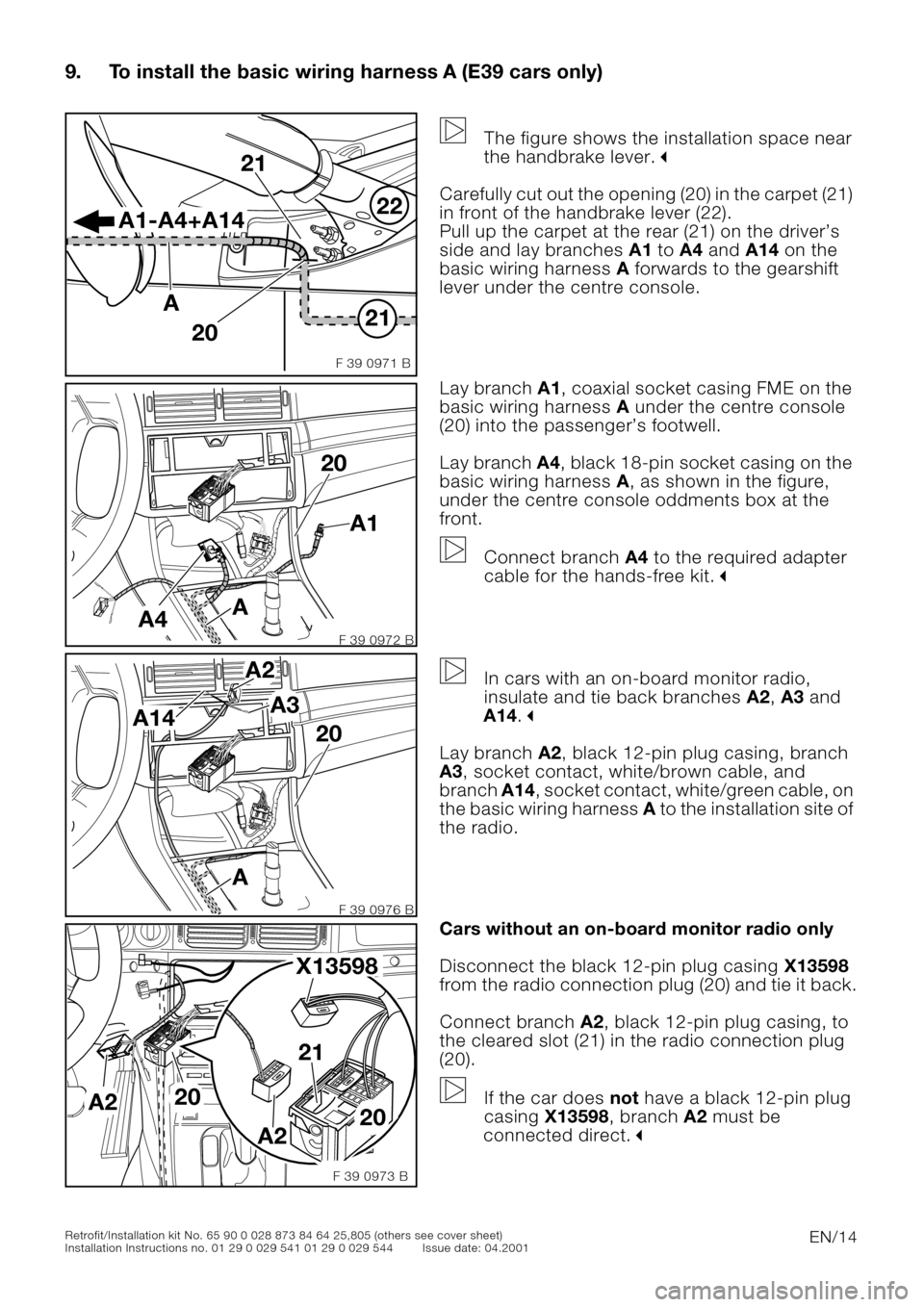
9. To install the basic wiring harness A (E39 cars only)
0
The figure shows the installation space near
the handbrake lever.
"
Carefully cut out the opening (20) in the carpet (21)
in front of the handbrake lever (22).
Pull up the carpet at the rear (21) on the driver’s
side and lay branches A1 to A4 and A14 on the
basic wiring harness A forwards to the gearshift
lever under the centre console.
0Lay branch A1, coaxial socket casing FME on the
basic wiring harness A under the centre console
(20) into the passenger’s footwell.
Lay branch A4, black 18-pin socket casing on the
basic wiring harness A, as shown in the figure,
under the centre console oddments box at the
front.
Connect branch A4 to the required adapter
cable for the hands-free kit.
"
0
In cars with an on-board monitor radio,
insulate and tie back branches A2, A3 and
A14.
"
Lay branch A2, black 12-pin plug casing, branch
A3, socket contact, white/brown cable, and
branch A14, socket contact, white/green cable, on
the basic wiring harness A to the installation site of
the radio.
0Cars without an on-board monitor radio only
Disconnect the black 12-pin plug casing X13598
from the radio connection plug (20) and tie it back.
Connect branch A2, black 12-pin plug casing, to
the cleared slot (21) in the radio connection plug
(20).
If the car does not have a black 12-pin plug
casing X13598, branch A2 must be
connected direct.
"
21
22
F 39 0971 B
A1-A4+A14
21
20 A
A1 20
A4
A
F 39 0972 B
20 A3 A2
A
A14
F 39 0976 B
20 21
20
A2
A2 X13598
F 39 0973 B
Page 15 of 36
EN/15Retrofit/Installation kit No. 65 90 0 028 873 84 64 25,805 (others see cover sheet)
Installation Instructions no. 01 29 0 029 541 01 29 0 029 544 Issue date: 04.2001
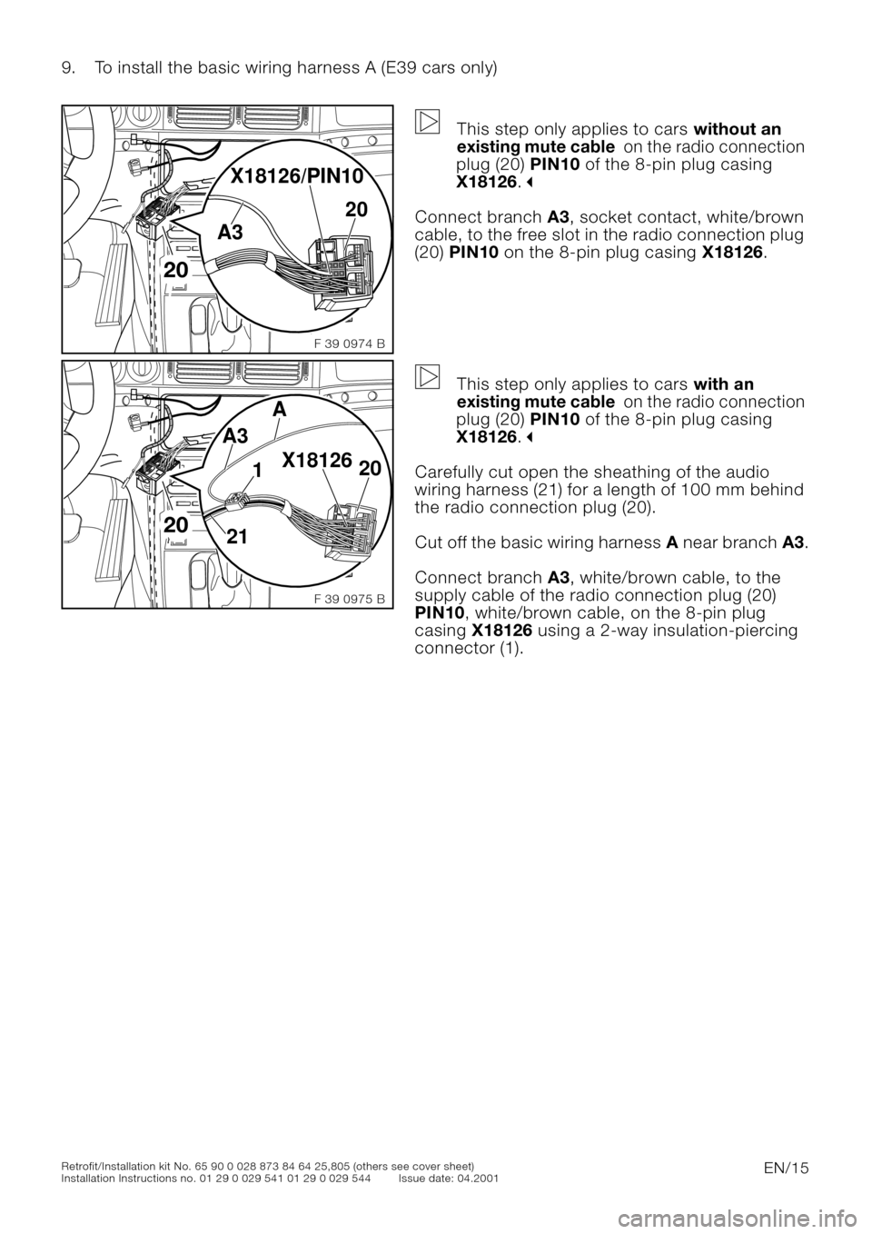
9. To install the basic wiring harness A (E39 cars only)
0
This step only applies to cars without an
existing mute cable on the radio connection
plug (20) PIN10 of the 8-pin plug casing
X18126.
"
Connect branch A3, socket contact, white/brown
cable, to the free slot in the radio connection plug
(20) PIN10 on the 8-pin plug casing X18126.
0
This step only applies to cars with an
existing mute cable on the radio connection
plug (20) PIN10 of the 8-pin plug casing
X18126.
"
Carefully cut open the sheathing of the audio
wiring harness (21) for a length of 100 mm behind
the radio connection plug (20).
Cut off the basic wiring harness A near branch A3.
Connect branch A3, white/brown cable, to the
supply cable of the radio connection plug (20)
PIN10, white/brown cable, on the 8-pin plug
casing X18126 using a 2-way insulation-piercing
connector (1).
20
F 39 0974 B
A3
X18126/PIN10
20
20
F 39 0975 B
A3
211
A
20 X18126
Page 16 of 36
EN/16Retrofit/Installation kit No. 65 90 0 028 873 84 64 25,805 (others see cover sheet)
Installation Instructions no. 01 29 0 029 541 01 29 0 029 544 Issue date: 04.2001
9. To install the basic wiring harness A (E39 cars only)
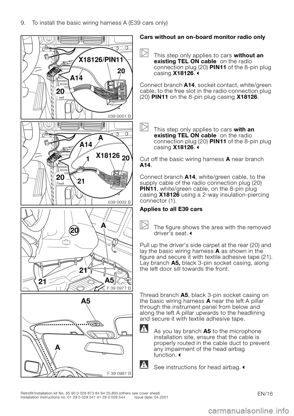
0Cars without an on-board monitor radio only
This step only applies to cars without an
existing TEL ON cable on the radio
connection plug (20) PIN11 of the 8-pin plug
casing X18126.
"
Connect branch A14, socket contact, white/green
cable, to the free slot in the radio connection plug
(20) PIN11 on the 8-pin plug casing X18126.
0
This step only applies to cars with an
existing TEL ON cable on the radio
connection plug (20) PIN11 of the 8-pin plug
casing X18126.
"
Cut off the basic wiring harness A near branch
A14.
Connect branch A14, white/green cable, to the
supply cable of the radio connection plug (20)
PIN11, white/green cable, on the 8-pin plug
casing X18126 using a 2-way insulation-piercing
connector (1).
0Applies to all E39 cars
The figure shows the area with the removed
driver’s seat.
"
Pull up the driver's side carpet at the rear (20) and
lay the basic wiring harness A as shown in the
figure and secure it with textile adhesive tape (21).
Lay branch A5, black 3-pin socket casing, along
the left door sill towards the front.
0Thread branch A5, black 3-pin socket casing on
the basic wiring harness A near the left A pillar
through the instrument panel from below and
along the left A pillar upwards to the headlining
and secure it with textile adhesive tape.
As you lay branch A5 to the microphone
installation site, ensure that the cable is
properly routed in the cable duct to prevent
any impairment of the head airbag
function.
"
See instructions for head airbag."
20
039 0001 B
A14
X18126/PIN11
20
20
039 0002 B
A14
211
A
20 X18126
21
21
A
A520
F 39 0977 B
F 39 0981 BIIIIIIIIIIIIIIIIIIIIIIIIIIIII
A5
A
!
!
Page 17 of 36
EN/17Retrofit/Installation kit No. 65 90 0 028 873 84 64 25,805 (others see cover sheet)
Installation Instructions no. 01 29 0 029 541 01 29 0 029 544 Issue date: 04.2001
9. To install the basic wiring harness A (E39 cars only)
0
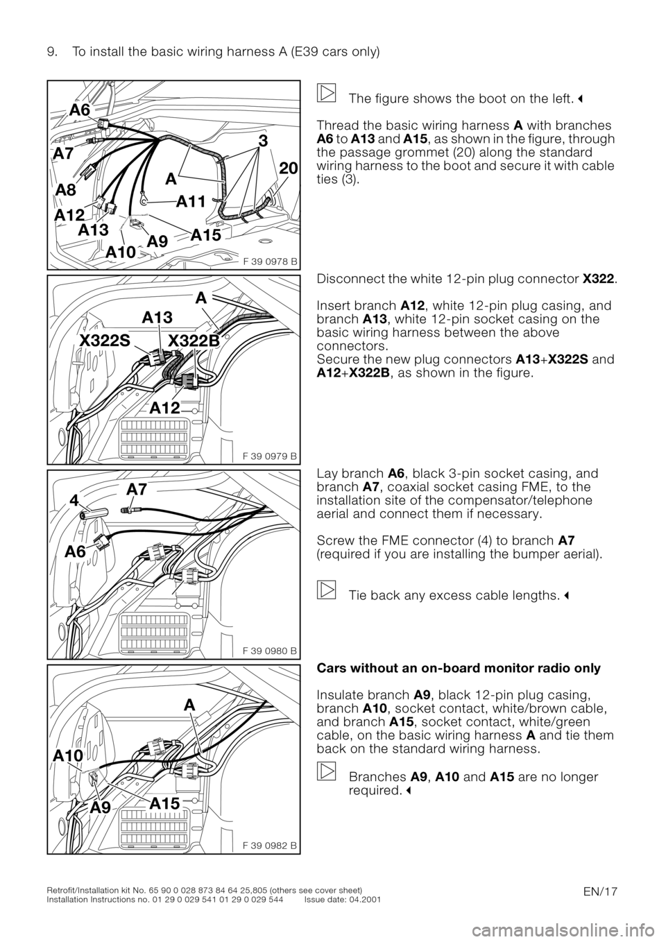
The figure shows the boot on the left."
Thread the basic wiring harness A with branches
A6 to A13 and A15, as shown in the figure, through
the passage grommet (20) along the standard
wiring harness to the boot and secure it with cable
ties (3).
0Disconnect the white 12-pin plug connector X322.
Insert branch A12, white 12-pin plug casing, and
branch A13, white 12-pin socket casing on the
basic wiring harness between the above
connectors.
Secure the new plug connectors A13+X322S and
A12+X322B, as shown in the figure.
0Lay branch A6, black 3-pin socket casing, and
branch A7, coaxial socket casing FME, to the
installation site of the compensator/telephone
aerial and connect them if necessary.
Screw the FME connector (4) to branch A7
(required if you are installing the bumper aerial).
Tie back any excess cable lengths.
"
0Cars without an on-board monitor radio only
Insulate branch A9, black 12-pin plug casing,
branch A10, socket contact, white/brown cable,
and branch A15, socket contact, white/green
cable, on the basic wiring harness A and tie them
back on the standard wiring harness.
Branches A9, A10 and A15 are no longer
required.
"
20
A
3
A11
A6
A13
A12A8
A7
A9A10
A15
F 39 0978 B
A12 X322S
A13
X322B
A
F 39 0979 B
A6
4A7
F 39 0980 B
A
A9 A10
A15
F 39 0982 B
Page 18 of 36
EN/18Retrofit/Installation kit No. 65 90 0 028 873 84 64 25,805 (others see cover sheet)
Installation Instructions no. 01 29 0 029 541 01 29 0 029 544 Issue date: 04.2001
9. To install the basic wiring harness A (E39 cars only)
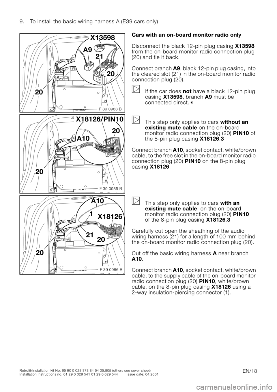
0Cars with an on-board monitor radio only
Disconnect the black 12-pin plug casing X13598
from the on-board monitor radio connection plug
(20) and tie it back.
Connect branch A9, black 12-pin plug casing, into
the cleared slot (21) in the on-board monitor radio
connection plug (20).
If the car does not have a black 12-pin plug
casing X13598, branch A9 must be
connected direct.
"
0
This step only applies to cars without an
existing mute cable on the on-board
monitor radio connection plug (20) PIN10 of
the 8-pin plug casing X18126.3
Connect branch A10, socket contact, white/brown
cable, to the free slot in the on-board monitor radio
connection plug (20) PIN10 on the 8-pin plug
casing X18126.
0
This step only applies to cars with an
existing mute cable on the on-board
monitor radio connection plug (20) PIN10
of the 8-pin plug casing X18126.3
Carefully cut open the sheathing of the audio
wiring harness (21) for a length of 100 mm behind
the on-board monitor radio connection plug (20).
Cut off the basic wiring harness A near branch
A10.
Connect branch A10, socket contact, white/brown
cable, to the supply cable of the on-board monitor
radio connection plug (20) PIN10, white/brown
cable, on the 8-pin plug casing X18126 using a
2-way insulation-piercing connector (1).
20
20 21 A9 X13598
F 39 0983 B
20
F 39 0985 B
A10
X18126/PIN10
20
20
F 39 0986 B
A10
211
20
X18126
Page 19 of 36
EN/19Retrofit/Installation kit No. 65 90 0 028 873 84 64 25,805 (others see cover sheet)
Installation Instructions no. 01 29 0 029 541 01 29 0 029 544 Issue date: 04.2001
9. To install the basic wiring harness A (E39 cars only)
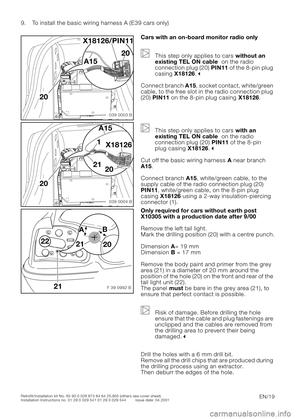
0Cars with an on-board monitor radio only
This step only applies to cars without an
existing TEL ON cable on the radio
connection plug (20) PIN11 of the 8-pin plug
casing X18126.
"
Connect branch A15, socket contact, white/green
cable, to the free slot in the radio connection plug
(20) PIN11 on the 8-pin plug casing X18126.
0
This step only applies to cars with an
existing TEL ON cable on the radio
connection plug (20) PIN11 of the 8-pin
plug casing X18126.
"
Cut off the basic wiring harness A near branch
A15.
Connect branch A15, white/green cable, to the
supply cable of the radio connection plug (20)
PIN11, white/green cable, on the 8-pin plug
casing X18126 using a 2-way insulation-piercing
connector (1).
0Only required for cars without earth post
X10305 with a production date after 9/00
Remove the left tail light.
Mark the drilling position (20) with a centre punch.
Dimension A= 19 mm
Dimension B = 17 mm
Remove the body paint and primer from the grey
area (21) in a diameter of 20 mm around the
position of the hole (20) on the front and rear of the
tail light unit (22).
The panel must be bare in the grey area (21), to
ensure that perfect contact is possible.
Risk of damage. Before drilling the hole
ensure that the cable and plug fastenings are
unclipped and the cables are removed from
the drilling area to prevent their being
damaged.
"
Drill the holes with a 6 mm drill bit.
Remove all the drill chips that are produced during
the drilling process using an extractor.
Then deburr the edges of the hole.
20
039 0003 B
A15
X18126/PIN11
20
20
039 0004 B
A15
211
20
X18126
F 39 0992 B21
22
A B
20 21
Page 20 of 36
EN/20Retrofit/Installation kit No. 65 90 0 028 873 84 64 25,805 (others see cover sheet)
Installation Instructions no. 01 29 0 029 541 01 29 0 029 544 Issue date: 04.2001
9. To install the basic wiring harness A (E39 cars only)
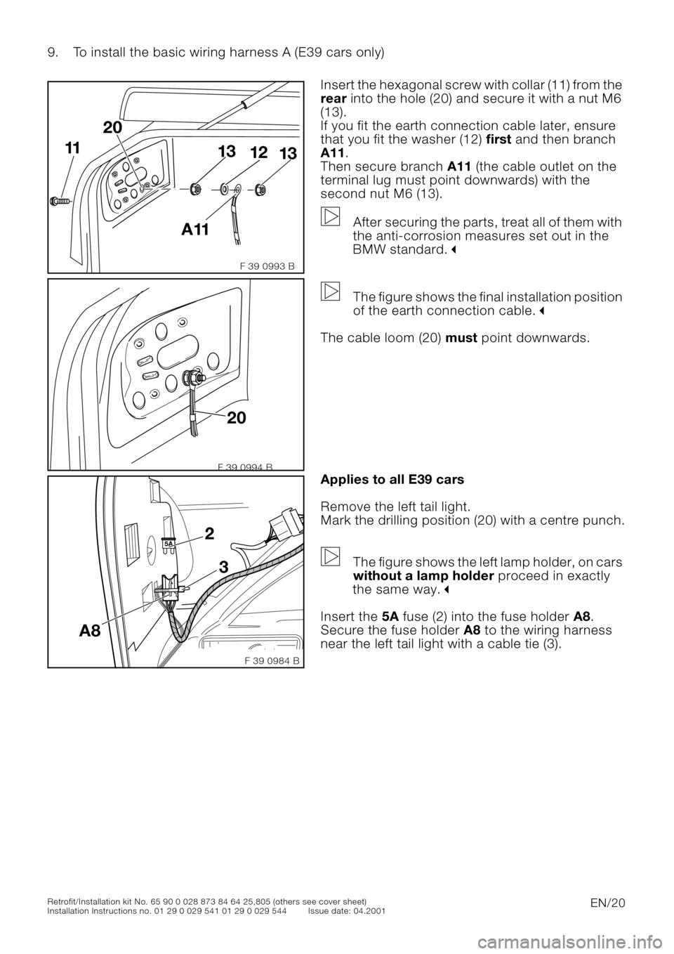
0Insert the hexagonal screw with collar (11) from the
rear into the hole (20) and secure it with a nut M6
(13).
If you fit the earth connection cable later, ensure
that you fit the washer (12) first and then branch
A11.
Then secure branch A11 (the cable outlet on the
terminal lug must point downwards) with the
second nut M6 (13).
After securing the parts, treat all of them with
the anti-corrosion measures set out in the
BMW standard.
"
0
The figure shows the final installation position
of the earth connection cable.
"
The cable loom (20) must point downwards.
0Applies to all E39 cars
Remove the left tail light.
Mark the drilling position (20) with a centre punch.
The figure shows the left lamp holder, on cars
without a lamp holder proceed in exactly
the same way.
"
Insert the 5A fuse (2) into the fuse holder A8.
Secure the fuse holder A8 to the wiring harness
near the left tail light with a cable tie (3).
F 39 0993 B
20
13
13 12 11
A11
20
F 39 0994 B
A83 2
5A
F 39 0984 B