Select display cluster BMW 5 SERIES 2015 F10 User Guide
[x] Cancel search | Manufacturer: BMW, Model Year: 2015, Model line: 5 SERIES, Model: BMW 5 SERIES 2015 F10Pages: 277, PDF Size: 5.63 MB
Page 95 of 277
For additional information, refer to Front fog
lights, refer to page 106.
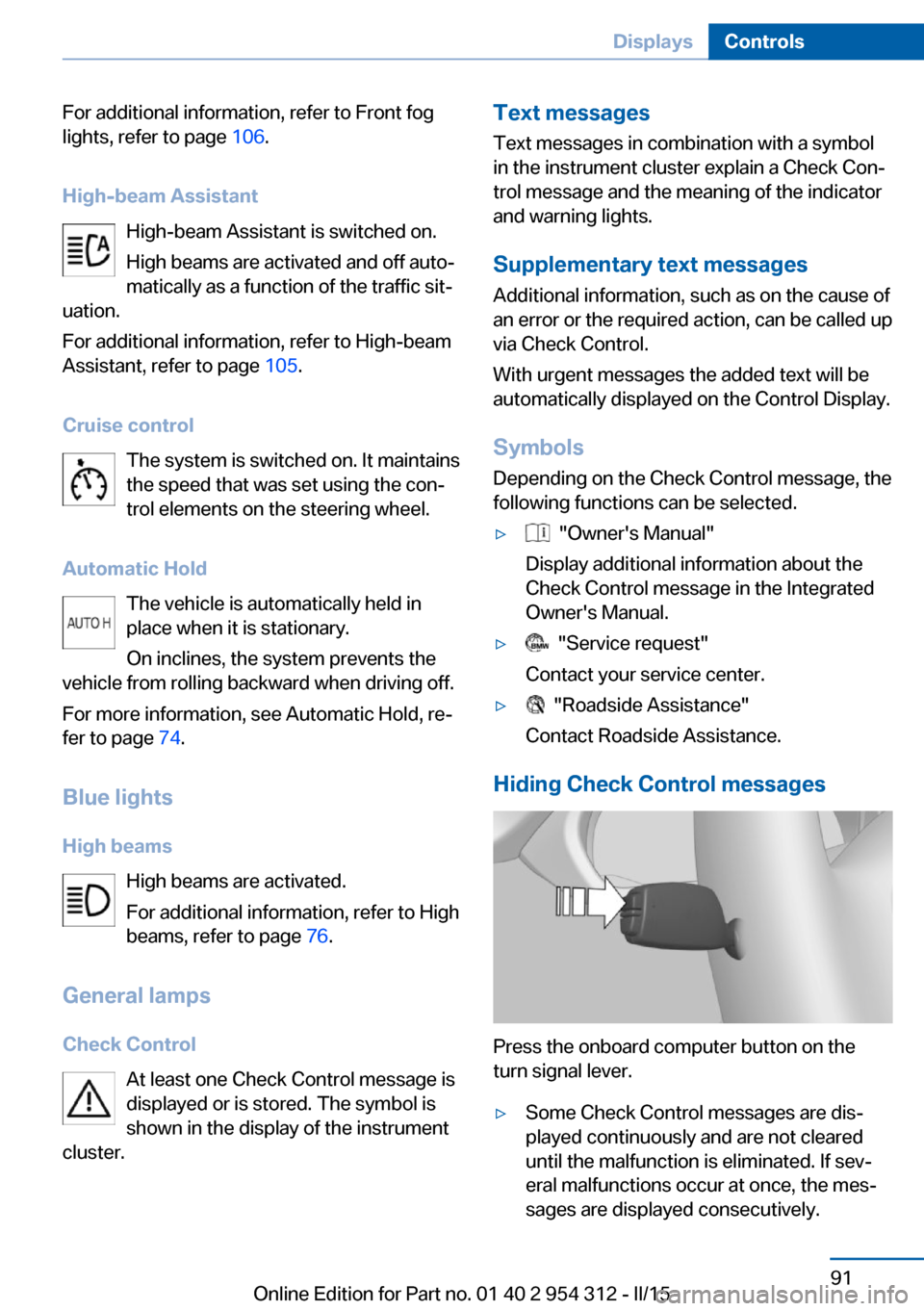
High-beam Assistant High-beam Assistant is switched on.
High beams are activated and off auto‐
matically as a function of the traffic sit‐
uation.
For additional information, refer to High-beam
Assistant, refer to page 105.
Cruise control The system is switched on. It maintains
the speed that was set using the con‐
trol elements on the steering wheel.
Automatic Hold The vehicle is automatically held in
place when it is stationary.
On inclines, the system prevents the
vehicle from rolling backward when driving off.
For more information, see Automatic Hold, re‐
fer to page 74.
Blue lights
High beams High beams are activated.
For additional information, refer to High
beams, refer to page 76.
General lamps
Check Control At least one Check Control message is
displayed or is stored. The symbol is
shown in the display of the instrument
cluster.Text messages
Text messages in combination with a symbol
in the instrument cluster explain a Check Con‐ trol message and the meaning of the indicator
and warning lights.
Supplementary text messages
Additional information, such as on the cause of
an error or the required action, can be called up
via Check Control.
With urgent messages the added text will be
automatically displayed on the Control Display.
Symbols Depending on the Check Control message, the
following functions can be selected.▷ "Owner's Manual"
Display additional information about the
Check Control message in the Integrated
Owner's Manual.▷ "Service request"
Contact your service center.▷ "Roadside Assistance"
Contact Roadside Assistance.
Hiding Check Control messages
Press the onboard computer button on the
turn signal lever.
▷Some Check Control messages are dis‐
played continuously and are not cleared
until the malfunction is eliminated. If sev‐
eral malfunctions occur at once, the mes‐
sages are displayed consecutively.Seite 91DisplaysControls91
Online Edition for Part no. 01 40 2 954 312 - II/15
Page 98 of 277
2."Instrument cluster"3."Additional indicators"
The bar display for the current fuel consump‐
tion is displayed in the instrument cluster.
Energy recovery
Display The kinetic energy of the vehicle
is converted to electrical energy
while coasting. The vehicle bat‐
tery is partially charged and fuel
consumption can be reduced.
Service requirements
The concept
After the ignition is turned on the instrument
cluster briefly displays available driving dis‐
tance or time to the next scheduled mainte‐
nance.
Your service specialist can read the current
service requirements from your remote con‐
trol.
Display
Data regarding the service status or legally
mandated vehicle inspections are automati‐
cally transmitted to your service center before
a service due date.
Detailed information on service
requirements
More information on the scope of service re‐
quired can be displayed on the Control Dis‐
play.
On the Control Display:
1."Vehicle info"2."Vehicle status"3. "Service required"Required maintenance procedures and le‐
gally mandated inspections are displayed.4.Select an entry to call up detailed informa‐
tion.
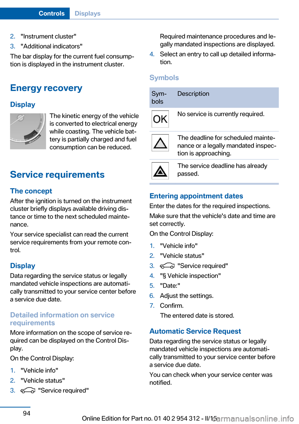
Symbols
Sym‐
bolsDescriptionNo service is currently required.The deadline for scheduled mainte‐
nance or a legally mandated inspec‐
tion is approaching.The service deadline has already
passed.
Entering appointment dates
Enter the dates for the required inspections.
Make sure that the vehicle's date and time are
set correctly.
On the Control Display:
1."Vehicle info"2."Vehicle status"3. "Service required"4."§ Vehicle inspection"5."Date:"6.Adjust the settings.7.Confirm.
The entered date is stored.
Automatic Service Request
Data regarding the service status or legally
mandated vehicle inspections are automati‐
cally transmitted to your service center before
a service due date.
You can check when your service center was
notified.
Seite 94ControlsDisplays94
Online Edition for Part no. 01 40 2 954 312 - II/15
Page 100 of 277
At a glance
Camera
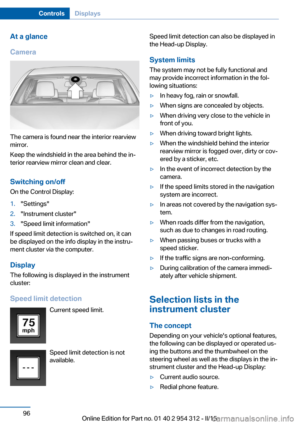
The camera is found near the interior rearview
mirror.
Keep the windshield in the area behind the in‐
terior rearview mirror clean and clear.
Switching on/offOn the Control Display:
1."Settings"2."Instrument cluster"3."Speed limit information"
If speed limit detection is switched on, it can
be displayed on the info display in the instru‐
ment cluster via the computer.
Display The following is displayed in the instrument
cluster:
Speed limit detection Current speed limit.
Speed limit detection is not available.
Speed limit detection can also be displayed in
the Head-up Display.
System limits The system may not be fully functional and
may provide incorrect information in the fol‐
lowing situations:▷In heavy fog, rain or snowfall.▷When signs are concealed by objects.▷When driving very close to the vehicle in
front of you.▷When driving toward bright lights.▷When the windshield behind the interior
rearview mirror is fogged over, dirty or cov‐
ered by a sticker, etc.▷In the event of incorrect detection by the
camera.▷If the speed limits stored in the navigation
system are incorrect.▷In areas not covered by the navigation sys‐
tem.▷When roads differ from the navigation,
such as due to changes in road routing.▷When passing buses or trucks with a
speed sticker.▷If the traffic signs are non-conforming.▷During calibration of the camera immedi‐
ately after vehicle shipment.
Selection lists in the
instrument cluster
The concept Depending on your vehicle's optional features,
the following can be displayed or operated us‐
ing the buttons and the thumbwheel on the
steering wheel as well as the displays in the in‐
strument cluster and the Head-up Display:
▷Current audio source.▷Redial phone feature.Seite 96ControlsDisplays96
Online Edition for Part no. 01 40 2 954 312 - II/15
Page 101 of 277
▷Turn on voice activation system.
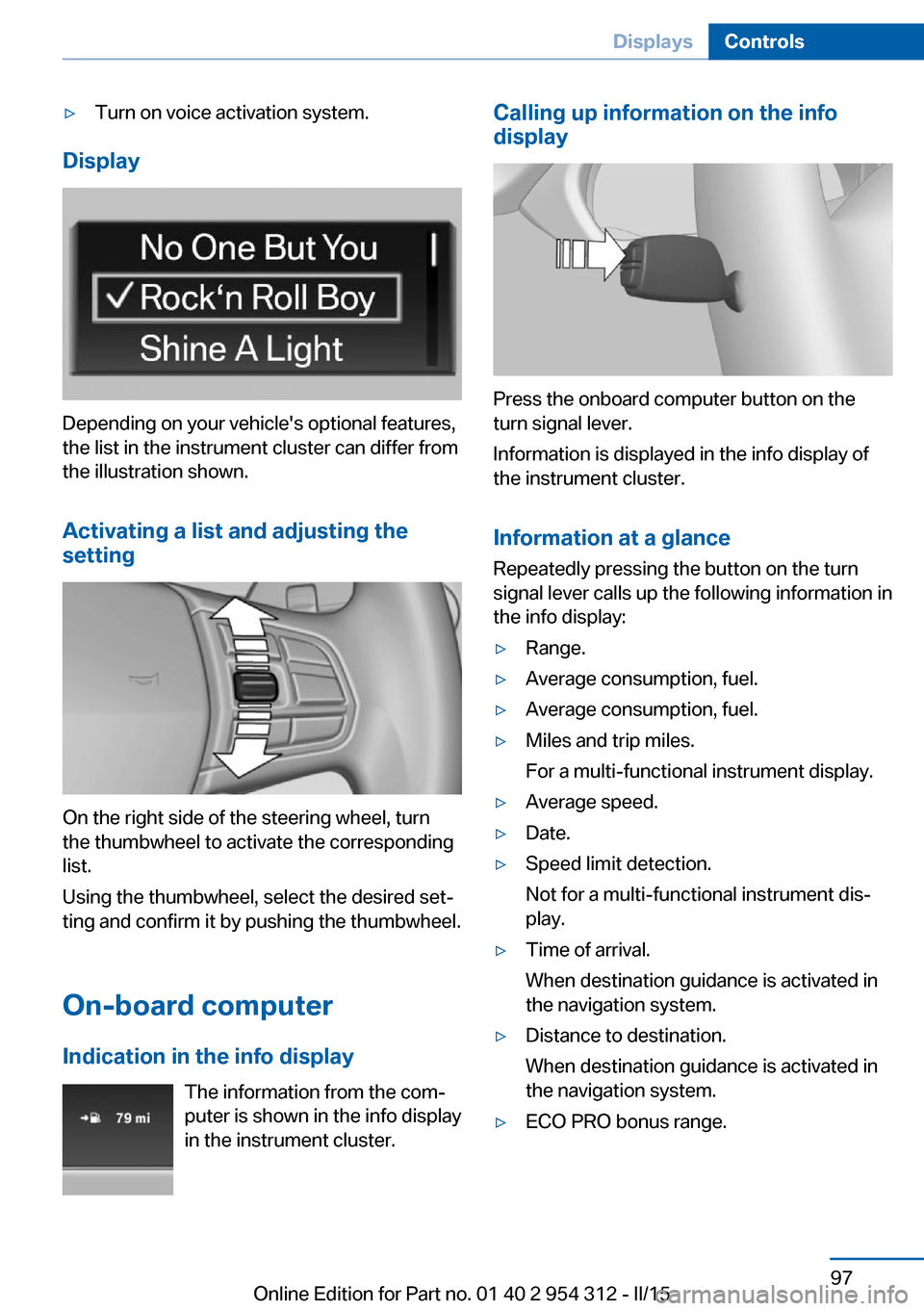
Display
Depending on your vehicle's optional features,
the list in the instrument cluster can differ from
the illustration shown.
Activating a list and adjusting the
setting
On the right side of the steering wheel, turn
the thumbwheel to activate the corresponding
list.
Using the thumbwheel, select the desired set‐
ting and confirm it by pushing the thumbwheel.
On-board computer
Indication in the info display The information from the com‐
puter is shown in the info display
in the instrument cluster.
Calling up information on the info
display
Press the onboard computer button on the
turn signal lever.
Information is displayed in the info display of
the instrument cluster.
Information at a glance
Repeatedly pressing the button on the turn
signal lever calls up the following information in
the info display:
▷Range.▷Average consumption, fuel.▷Average consumption, fuel.▷Miles and trip miles.
For a multi-functional instrument display.▷Average speed.▷Date.▷Speed limit detection.
Not for a multi-functional instrument dis‐
play.▷Time of arrival.
When destination guidance is activated in
the navigation system.▷Distance to destination.
When destination guidance is activated in
the navigation system.▷ECO PRO bonus range.Seite 97DisplaysControls97
Online Edition for Part no. 01 40 2 954 312 - II/15
Page 102 of 277
Adjusting the info display
Depending on the vehicle equipment version,
you can select what information from the com‐
puter is to be displayed on the info display of
the instrument cluster.
On the Control Display:1."Settings"2."Instrument cluster"3.Select the desired displays.
Information in detail
Range
Displays the estimated cruising range available
with the remaining fuel.
It is calculated based on your driving style over
the last 20 miles/30 km.
If there is only enough fuel left for less than
45 miles/80 km, the color of the display
changes.
Average fuel consumption
The average fuel consumption is calculated for
the period while the engine is running.
The average fuel consumption is calculated for
the distance traveled since the last reset by the
on-board comupter.
Average speed
Periods in which the vehicle is parked with the
engine manually stopped are not included in
the calculation of the average speed.
Resetting average values
Press and hold the onboard computer button
on the turn signal lever.
Distance to destination
The distance remaining to the destination is
displayed if a destination is entered in the navi‐
gation system before the trip is started.
The distance to the destination is adopted au‐
tomatically.
Time of arrival The estimated time of arrival is
displayed if a destination is en‐
tered in the navigation system
before the trip is started.
The time must be correctly set.
Speed limit detection Description of the speed limit detection, refer
to page 95, function.
Trip computer The vehicle features two types of board com‐
puters.▷"Onboard info": the values can be reset as
often as necessary.▷"Trip computer": the values provide an
overview of the current trip.
Resetting the trip computer
On the Control Display:
1."Vehicle info"2."Trip computer"3."Reset": all values are reset.
"Automatically reset": all values are reset
approx. 4 hours after the vehicle came to a
standstill.
Display on the Control Display
Display the computer or trip computer on the
Control Display.
1."Vehicle info"2."Onboard info" or "Trip computer"Seite 98ControlsDisplays98
Online Edition for Part no. 01 40 2 954 312 - II/15
Page 105 of 277
Depending on the light conditions, the bright‐
ness settings may not be clearly visible.
Head-up Display
The concept
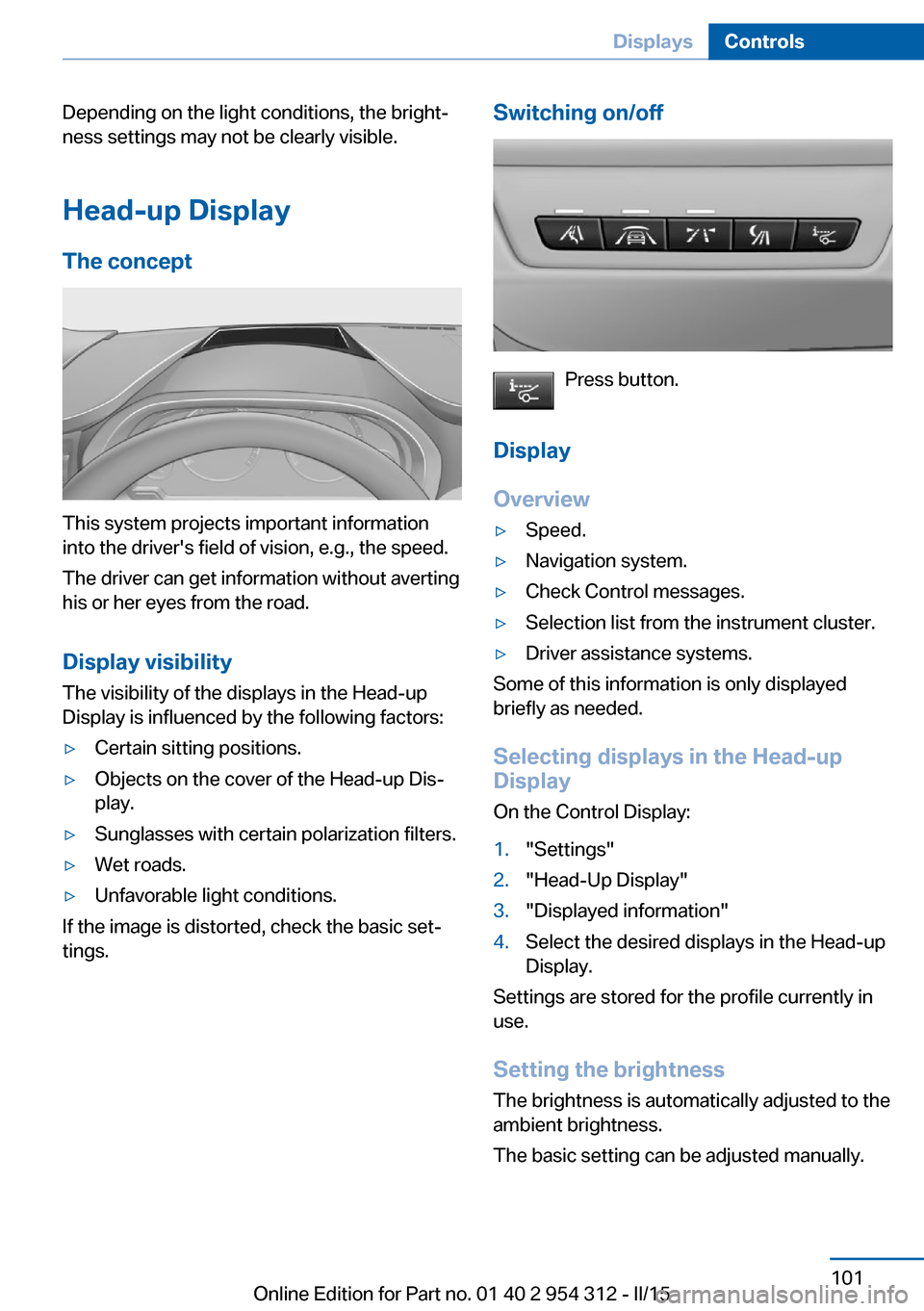
This system projects important information
into the driver's field of vision, e.g., the speed.
The driver can get information without averting
his or her eyes from the road.
Display visibility The visibility of the displays in the Head-up
Display is influenced by the following factors:
▷Certain sitting positions.▷Objects on the cover of the Head-up Dis‐
play.▷Sunglasses with certain polarization filters.▷Wet roads.▷Unfavorable light conditions.
If the image is distorted, check the basic set‐
tings.
Switching on/off
Press button.
Display
Overview
▷Speed.▷Navigation system.▷Check Control messages.▷Selection list from the instrument cluster.▷Driver assistance systems.
Some of this information is only displayed
briefly as needed.
Selecting displays in the Head-up
Display
On the Control Display:
1."Settings"2."Head-Up Display"3."Displayed information"4.Select the desired displays in the Head-up
Display.
Settings are stored for the profile currently in
use.
Setting the brightness
The brightness is automatically adjusted to the
ambient brightness.
The basic setting can be adjusted manually.
Seite 101DisplaysControls101
Online Edition for Part no. 01 40 2 954 312 - II/15
Page 123 of 277
At a glance
Button in the vehicle
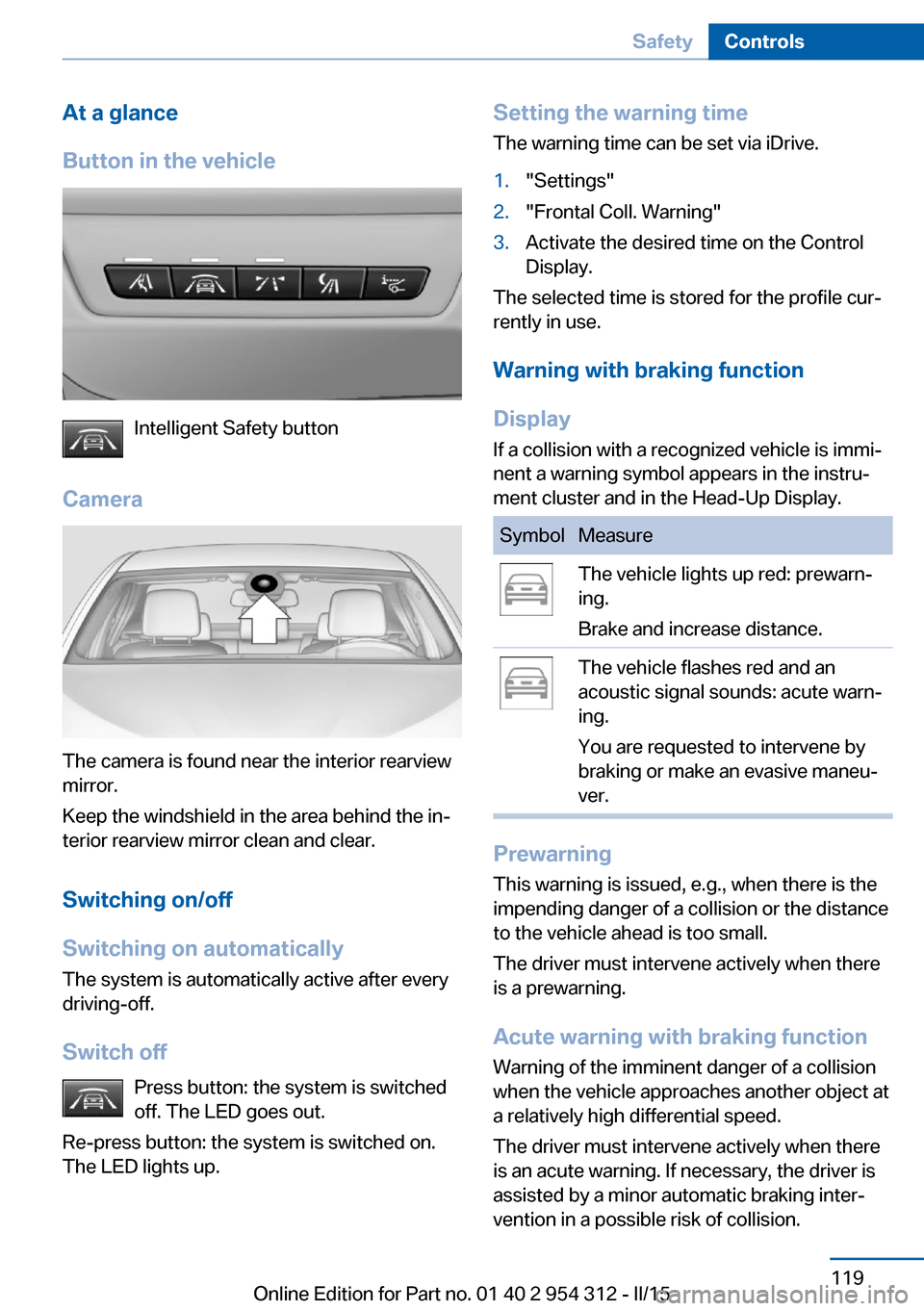
Intelligent Safety button
Camera
The camera is found near the interior rearview
mirror.
Keep the windshield in the area behind the in‐
terior rearview mirror clean and clear.
Switching on/off
Switching on automatically The system is automatically active after every
driving-off.
Switch off Press button: the system is switched
off. The LED goes out.
Re-press button: the system is switched on.
The LED lights up.
Setting the warning time
The warning time can be set via iDrive.1."Settings"2."Frontal Coll. Warning"3.Activate the desired time on the Control
Display.
The selected time is stored for the profile cur‐
rently in use.
Warning with braking function
Display If a collision with a recognized vehicle is immi‐
nent a warning symbol appears in the instru‐
ment cluster and in the Head-Up Display.
SymbolMeasureThe vehicle lights up red: prewarn‐
ing.
Brake and increase distance.The vehicle flashes red and an
acoustic signal sounds: acute warn‐
ing.
You are requested to intervene by
braking or make an evasive maneu‐
ver.
Prewarning
This warning is issued, e.g., when there is the
impending danger of a collision or the distance
to the vehicle ahead is too small.
The driver must intervene actively when there
is a prewarning.
Acute warning with braking function
Warning of the imminent danger of a collision
when the vehicle approaches another object at
a relatively high differential speed.
The driver must intervene actively when there
is an acute warning. If necessary, the driver is
assisted by a minor automatic braking inter‐
vention in a possible risk of collision.
Seite 119SafetyControls119
Online Edition for Part no. 01 40 2 954 312 - II/15
Page 126 of 277
Camera
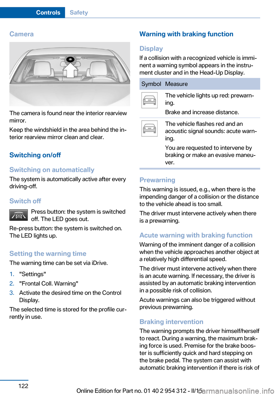
The camera is found near the interior rearview
mirror.
Keep the windshield in the area behind the in‐
terior rearview mirror clean and clear.
Switching on/off
Switching on automatically The system is automatically active after every
driving-off.
Switch off Press button: the system is switched
off. The LED goes out.
Re-press button: the system is switched on.
The LED lights up.
Setting the warning time The warning time can be set via iDrive.
1."Settings"2."Frontal Coll. Warning"3.Activate the desired time on the Control
Display.
The selected time is stored for the profile cur‐
rently in use.
Warning with braking function
Display
If a collision with a recognized vehicle is immi‐
nent a warning symbol appears in the instru‐
ment cluster and in the Head-Up Display.SymbolMeasureThe vehicle lights up red: prewarn‐
ing.
Brake and increase distance.The vehicle flashes red and an
acoustic signal sounds: acute warn‐
ing.
You are requested to intervene by
braking or make an evasive maneu‐
ver.
Prewarning
This warning is issued, e.g., when there is the
impending danger of a collision or the distance
to the vehicle ahead is too small.
The driver must intervene actively when there
is a prewarning.
Acute warning with braking function
Warning of the imminent danger of a collision
when the vehicle approaches another object at
a relatively high differential speed.
The driver must intervene actively when there
is an acute warning. If necessary, the driver is
assisted by an automatic braking intervention
in a possible risk of collision.
Acute warnings can also be triggered without
previous prewarning.
Braking intervention The warning prompts the driver himself/herself
to react. During a warning, the maximum brak‐
ing force is used. Premise for the brake boos‐
ter is sufficiently quick and hard stepping on
the brake pedal. The system can assist with
automatic braking intervention if there is risk of
Seite 122ControlsSafety122
Online Edition for Part no. 01 40 2 954 312 - II/15
Page 132 of 277
Adjustments via the iDrive
With heat image switched on:1.Press the controller.2.Select brightness or contrast.▷ Select the symbol.▷ Select the symbol.3.Turn the controller until the desired setting
is selected.4.Press the controller.
Display
Warning of people or animals in
danger
If a collision with a person or an animal de‐
tected in this way is imminent, a warning sym‐
bol appears on the instrument cluster and in
the Head-up Display.
Although both the shape and the heat radiation
are analyzed, false warnings cannot be ruled
out.
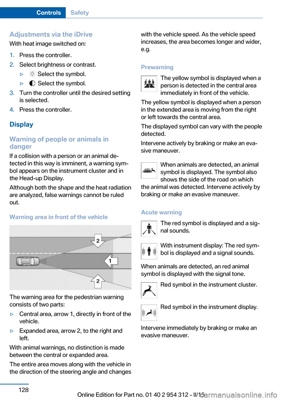
Warning area in front of the vehicle
The warning area for the pedestrian warning
consists of two parts:
▷Central area, arrow 1, directly in front of the
vehicle.▷Expanded area, arrow 2, to the right and
left.
With animal warnings, no distinction is made
between the central or expanded area.
The entire area moves along with the vehicle in
the direction of the steering angle and changes
with the vehicle speed. As the vehicle speed
increases, the area becomes longer and wider,
e.g.
Prewarning The yellow symbol is displayed when aperson is detected in the central area
immediately in front of the vehicle.
The yellow symbol is displayed when a person
in the extended area is moving from the right
or left towards the central area.
The displayed symbol can vary with the people
detected.
Intervene actively by braking or make an eva‐
sive maneuver.
When animals are detected, an animal
symbol is displayed. The symbol also
shows the side of the road on which
the animal was detected. Intervene actively by
braking or make an evasive maneuver.
Acute warning The red symbol is displayed and a sig‐
nal sounds.
With instrument display: The red sym‐
bol is displayed and a signal sounds.
When animals are detected, an red animal
symbol is displayed with the signal tone.
Red symbol in the instrument cluster.
Red symbol in the instrument display.
Intervene immediately by braking or make an
evasive maneuver.Seite 128ControlsSafety128
Online Edition for Part no. 01 40 2 954 312 - II/15
Page 141 of 277
▷When freeing vehicle from deep snow or
driving off from loose grounds.▷When driving with snow chains.
Deactivating/activating DTC Dynamic
Traction Control
Activating DTC Press button.
TRACTION is displayed in the instru‐
ment cluster and the indicator lamp for DSC
OFF lights up.
Deactivating DTC Press button again.
TRACTION and the DSC OFF indica‐
tor lamp go out.
Indicator/warning lights
If DTC is activated, TRACTION is displayed in
the instrument cluster.
The indicator lamp lights up: DTC Dy‐
namic Traction Control is activated.
xDrive xDrive is the all-wheel-drive system of your ve‐
hicle. Concerted action by the xDrive and DSC
further optimize traction and driving dynamics.
The xDrive all-wheel-drive system variably dis‐
tributes the drive forces to the front and rear
axles as demanded by the driving situation and
road surface.
HDC Hill Descent Control
The concept HDC is a downhill driving assistant that auto‐
matically controls vehicle speed on steep
downhill gradients. Without applying the
brakes, the vehicle moves at slightly more than
walking speed.
Hill Descent Control can be activated at
speeds below approx. 22 mph/35 km/h. When
driving downhill, the vehicle reduces its speed
to approx. walking speed and then keeps its
speed constant.
As long as there is active braking, the system
is on standby. The system does not brake the
vehicle during this time.
Only use HDC in low gears or in selector lever
position D or R.
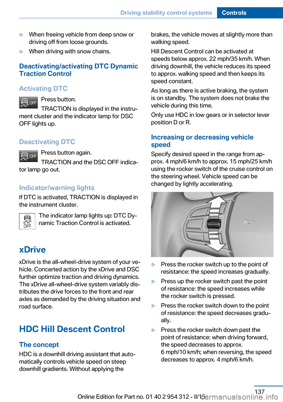
Increasing or decreasing vehicle
speed
Specify desired speed in the range from ap‐
prox. 4 mph/6 km/h to approx. 15 mph/25 km/h
using the rocker switch of the cruise control on
the steering wheel. Vehicle speed can be
changed by lightly accelerating.▷Press the rocker switch up to the point of
resistance: the speed increases gradually.▷Press up the rocker switch past the point
of resistance: the speed increases while
the rocker switch is pressed.▷Press the rocker switch down to the point
of resistance: the speed decreases gradu‐
ally.▷Press the rocker switch down past the
point of resistance: when driving forward,
the speed decreases to approx.
6 mph/10 km/h; when reversing, the speed
decreases to approx. 4 mph/6 km/h.Seite 137Driving stability control systemsControls137
Online Edition for Part no. 01 40 2 954 312 - II/15