clock BMW 525i 1998 E39 Owner's Guide
[x] Cancel search | Manufacturer: BMW, Model Year: 1998, Model line: 525i, Model: BMW 525i 1998 E39Pages: 1002
Page 423 of 1002
Downloaded from www.Manualslib.com manuals search engine
Fuel lniection I
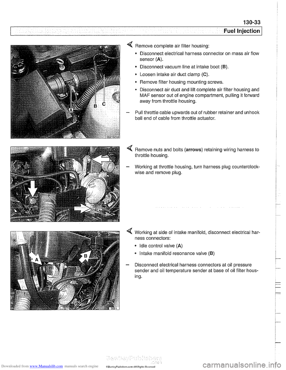
4 Remove complete air filter housing:
Disconnect electrical harness connector on mass air flow
sensor
(A).
Disconnect vacuum line at intake boot (B).
Loosen Intake air duct clamp (C).
Remove filter housing mounting screws
Disconnect air duct and
lift complete air filter housing and
MAF sensor out of engine compartment, pulling it forward
away from throttle housing.
- Pull throttle cable upwards out of rubber retainer and unhoolc
ball end of cable from throttle actuator.
4 Remove nuts and bolts (arrows) retaining wiring harness to
throttle housing.
- Working at throttle housing, turn harness plug counterclock-
wise and remove plug.
4 Working at side of intake manifold, disconnect electrical har-
ness connectors:
Idle control valve (A)
lntalce manifold resonance valve (B)
- Disconnect electrical harness connectors at oil pressure
sender and oil temperature sender at base of oil filter hous-
ing.
CO,l,> ti,, "F"bl,rl,irrm.,-AI ",",>ti
Page 424 of 1002
Downloaded from www.Manualslib.com manuals search engine
/Fuel Injection
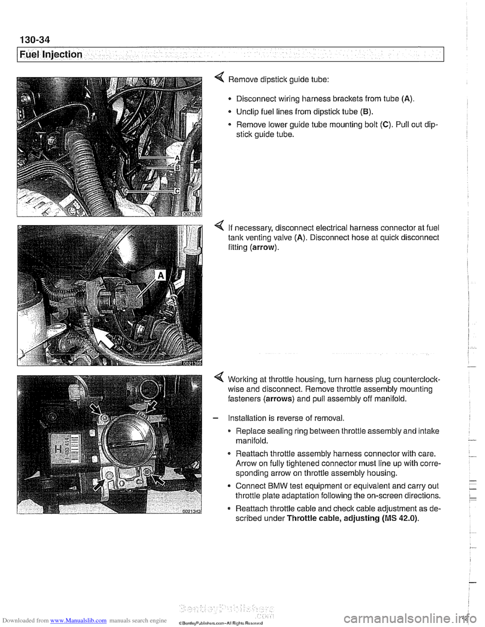
4 Remove dipstick guide tube:
Disconnect wiring harness brackets from tube (A).
Unclip fuel lines from dipstick tube
(El).
Remove lower guide tube mounting bolt (C). Pull out dip-
stick guide tube.
< If necessary, disconnect electrical harness connector at fuel
tank venting valve (A). Disconnect hose at quick disconnect
fitting (arrow).
Working at throttle housing, turn harness plug counterclock-
wise and disconnect. Remove throttle assembly mounting
fasteners (arrows) and pull assembly off manifold.
Installation is reverse of removal
Replace sealing ring between throttle assembly and intake
manifold.
0 Reattach throttle assembly harness connector with care.
Arrow on fully tightened connector must line up with corre-
sponding arrow on throttle assembly housing.
* Connect BMW test equipment or equivalent and carry out
throttle plate adaptation following the on-screen directions.
Reattach throttle cable and check cable adjustment as de-
scribed under Throttle cable, adjusting
(MS 42.0).
Page 427 of 1002
Downloaded from www.Manualslib.com manuals search engine
-.
Fuel Injection 1
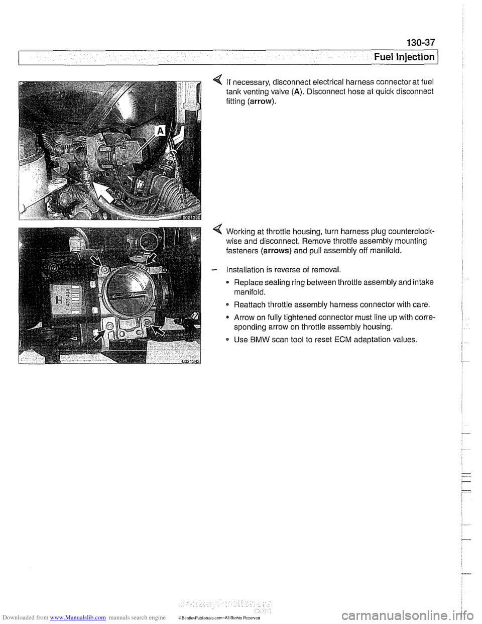
4 If necessary, disconnect electrical harness connector at fuel
tank venting valve (A). Disconnect hose at quick disconnect
fitting
(arrow).
< Worlting at throttle housing, turn harness plug counterclock-
wise and disconnect. Remove throttle assembly mounting
fasteners
(arrows) and pull assembly off manifold.
- Installation is reverse of removal.
0 Replace sealing ring between throttle assembly and intake
manifold.
Reattach throttle assembly harness connector with care.
0 Arrow on fully tightened connector must line up with corre-
sponding arrow on throttle assembly housing.
- Use BMW scan tool to reset ECM adaptation values.
Page 511 of 1002
Downloaded from www.Manualslib.com manuals search engine
Radiator and Cooling System
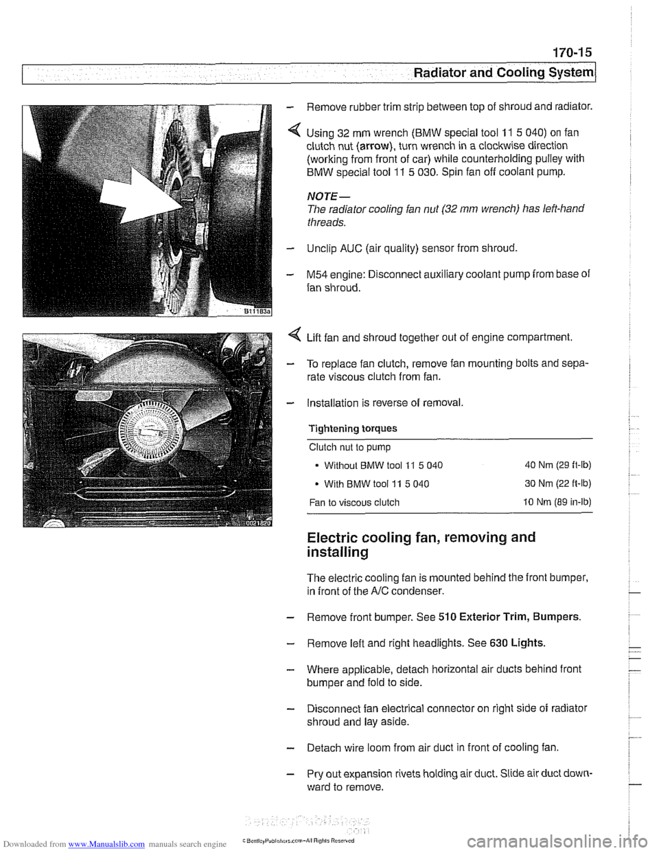
Remove rubber trim strip between top of shroud and radiator.
Using 32 mm wrench
(BMW special tool 11 5 040) on fan
clutch nut (arrow), turn wrench in a clockwise direction
(working from front of car) while counterholding pulley with
BMW special tool
11 5 030. Spin fan off coolant pump.
NOTE-
The radiator cooling fan nut (32 mm wrench) has left-hand
threads.
Unclip AUC (air quality) sensor from shroud,
M54 engine: Disconnect auxiliary coolant pump from base of
fan shroud.
Lift fan and shroud together out of engine compartment.
To replace fan clutch, remove fan mounting bolts and sepa-
rate viscous clutch from fan.
Installation is reverse of removal.
Tightening
torques
Clutch nut to pump
Without
BMW tool 11 5 040 40 Nm (29 ft-lb)
With BMW tool 11 5 040 30 Nm
(22 ft-lb)
Fan to viscous clutch 10 Nm (89 in-lb)
Electric cooling fan, removing and
installing
The electric cooling fan is mounted behind the front bumper,
in front of the
A/C condenser.
- Remove front bumper. See 510 Exterior Trim, Bumpers.
- Remove left and right headlights. See 630 Lights,
- Where applicable, detach horizontal air ducts behind front
bumper and fold to side.
- Disconnect fan electrical connector on right side of radiator
shroud and lay aside.
- Detach wire loom from air duct in front of cooling fan
- Pry out expansion rivets holding air duct. Slide air duct down-
ward to remove.
Page 519 of 1002
Downloaded from www.Manualslib.com manuals search engine
. --
Radiator and Cooling system/
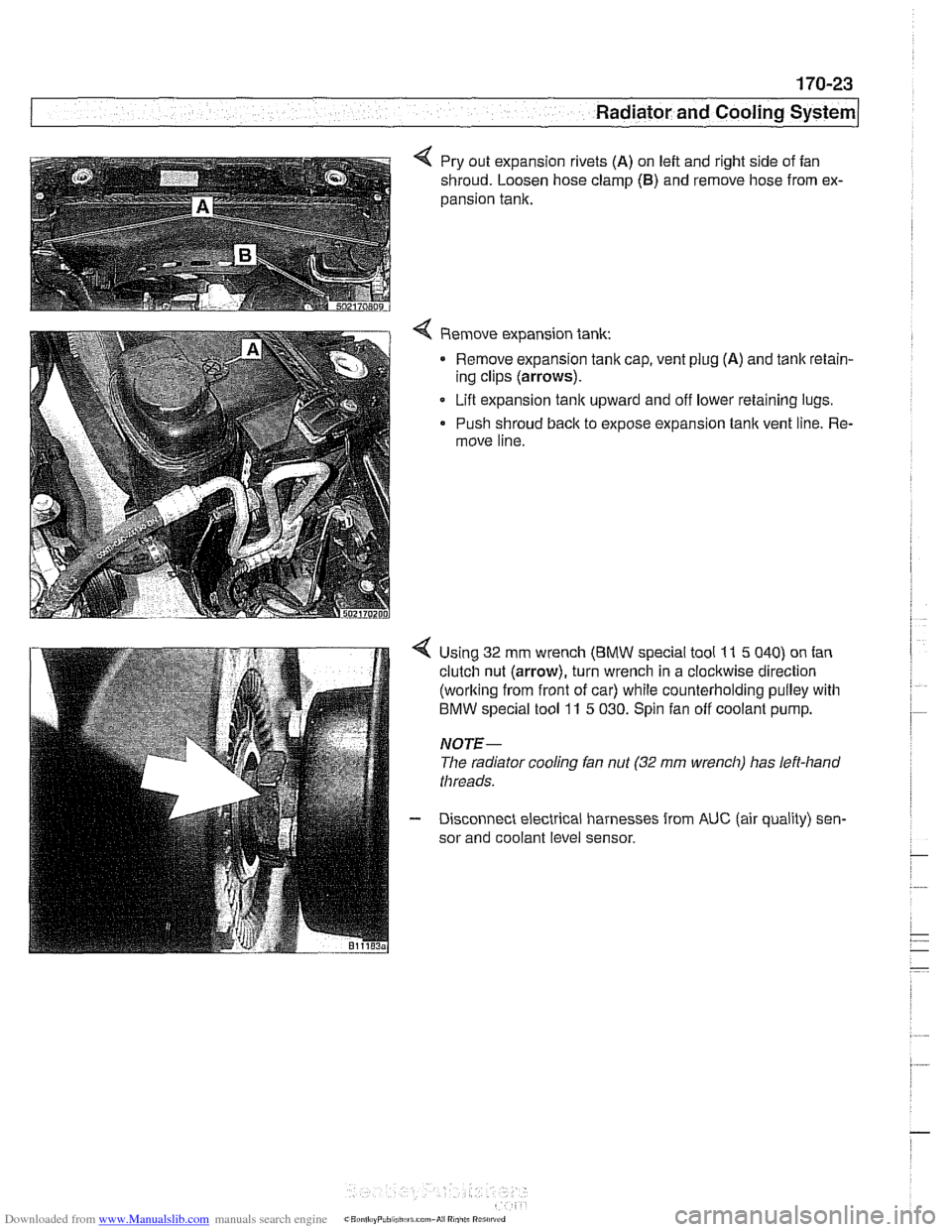
4 Pry out expansion rivets (A) on left and right side of fan
shroud. Loosen hose clamp
(6) and remove hose from ex-
pansion tank.
Remove expansion tank: Remove expansion tanlc cap, vent plug
(A) and tank retain-
ing clips (arrows).
Lift expansion
tanlc upward and off lower retaining lugs.
Push shroud back to expose expansion tank vent line. Re-
move line.
Using 32 mm wrench
(BMW special tool 11 5 040) on fan
clutch nut (arrow), turn wrench in a clockwise direction
(working from front of car) while counterholding pulley with
BMW special tool 11 5 030. Spin fan off coolant pump.
NOTE-
The radiator cooling fan nut (32 mrn wrench) has left-hand
threads.
Disconnect electrical harnesses from
AUC (air quality) sen-
sor and coolant level sensor.
Page 560 of 1002
Downloaded from www.Manualslib.com manuals search engine
21 0-1 8
Clutch
- lnstall flywheel lock, special tool 11 2 170 (6 cylinder model)
or
11 2 070 (V-8 model).
- Install SAC pressure plate on dowel pins at flywheel. lnstall
clutch mounting bolts and tighten each one turn at a time until
pressure plate is fully seated. Torque to specification.
Tightening torques Clutch to flywheel
- M8 (8.8 grade)
MB 110.9 orade)
24 Nm (1 8 it-lb)
34 Nm (25
ft-lb)
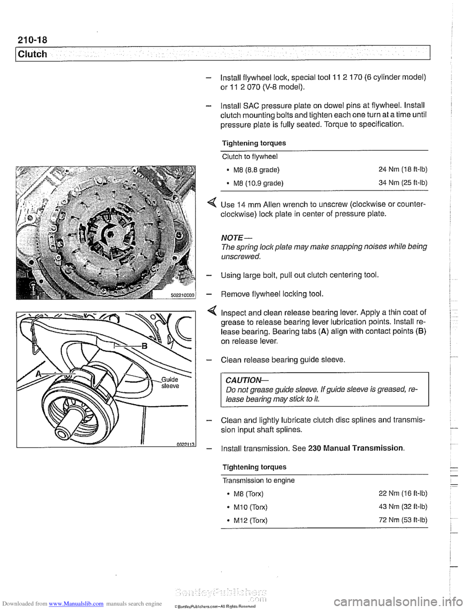
Use 14 mm Allen wrench to unscrew (clocltwise or counter-
clockwise) lock plate in center of pressure plate.
NOTE-
The spring lockplate may make snapping noises while being
unscrewed.
Using large bolt, pull out clutch centering tool
Remove flywheel locking tool
4 Inspect and clean release bearing lever. Apply a thin coat of
grease to release bearing lever lubrication points. lnstall re-
lease bearing. Bearing tabs
(A) align with contact points (B)
on release lever.
- Clean release bearing guide sleeve.
CAUTIOG
Do not grease guide sleeve. Ifguide sleeve is greased, re-
lease bearing may stick to it.
- Clean and lightly lubricate clutch disc splines and transmis-
sion input shaft splines.
- lnstall transmission. See 230 Manual Transmission.
Tightening torques
- - - Transmlsslon to engine -
. MB (Torx) 22
Nm (16 it-lb)
MI0 (Torx) 43 Nm (32 it-lb)
* M12 (Torx) 72 Nm (53 it-lb)
.-
Page 602 of 1002
Downloaded from www.Manualslib.com manuals search engine
250-4
I Gearshift Linkage
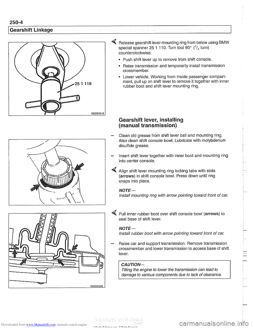
Release gearshift lever mounting ring from below using BMW
special spanner 25 1 110. Turn tool 90' ('I, turn)
counterclockwise.
Push shift lever up to remove from shift console,
Raise transmission and temporarily install transmission
crossmember.
Lower vehicle. Working from inside passenger compart-
ment, pull up on shift lever to remove it together with inner
rubber boot and shift lever mounting ring.
Gearshift lever, installing
(manual transmission)
- Clean old grease from shift lever ball and mounting ring.
Also clean shift console bowl. Lubricate with molybdenum
disulfide grease.
- Insert shift lever together with inner boot and mounting ring
into center console.
4 Align shift lever mounting ring locking tabs with slots
(arrows) in shift console bowl. Press down until ring
snaps into place.
NOTE-
lnstall mounting ring witli arrow pointing toward front of car.
4 Pull inner rubber boot over shift console bowl (arrows) to
seal base of shift lever.
NOTE-
lnstall rubber boot witli arrow pointing toward front of car.
- Raise car and support transmission. Remove transmission
crossmember and lower transmission to access base of shift
lever.
CAUTIOI\C
Tilting the engine to lower the transmission can lead to
damage to various components due to lack of clearance.
Page 670 of 1002
Downloaded from www.Manualslib.com manuals search engine
I Steering and Wheel Alignment
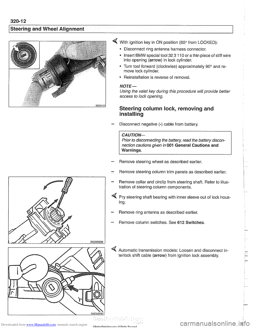
With ignition key in ON position (60" from LOCKED):
- Disconnect ring antenna harness connector.
Insert
BMW special tool 32 3 110 or a thin piece of stiff wire
into opening (arrow) in lock cylinder.
Turn tool forward (clockwise) approximately 90" and re-
move lock cylinder.
* Reinstallation is reverse of removal.
NOTE-
Using the valet ley during this procedure will provide better
access to lock opening.
Steering column lock, removing and
installing
- Disconnect negative (-) cable from battery.
CAUTIO&
Prior to disconnecting the battery, read the battery discon-
nection cautions given
in 001 General Cautions and
Warnings.
- Remove steering wheel as described earlier.
- Remove steering column trim panels as described earlier.
- Remove collar and circlip from steering shaft. Refer to illus-
tration of steering column components.
4 Pry steering shaft bearing with inner sleeve out of lock hous-
ing.
- Remove ring antenna as described earlier.
- Remove column switches. See 612 Switches.
< Automatic transmission models: Loosen and disconnect in-
terloclc shift cable (arrow) from ignition lock assembly.
Page 913 of 1002
Downloaded from www.Manualslib.com manuals search engine
Central Locking and Anti-Theft
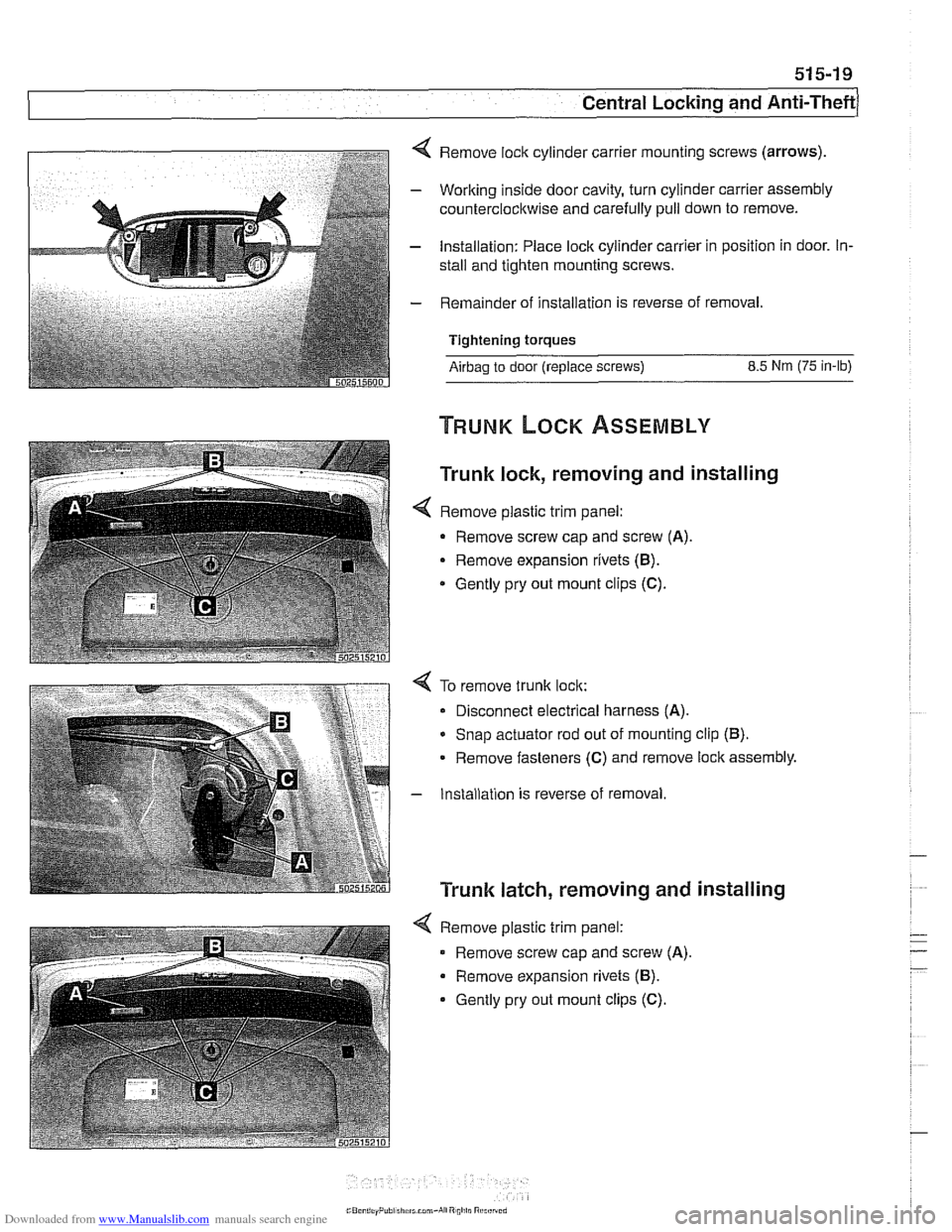
4 Remove lock cylinder carrier mounting screws (arrows).
- Working inside door cavity, turn cylinder carrier assembly
counterclockwise and carefully pull down to remove.
- Installation: Place lock cylinder carrier in position in door. In-
stall and tighten mounting screws.
- Remainder of installation is reverse of removal.
Tightening torques
Airbag to door (replace screws) 8.5 Nm (75 in-lb)
Trunk lock, removing and installing
< Remove plastic trim panel:
- Remove screw cap and screw (A).
Remove expansion rivets (B).
* Gently pry out mount clips (C).
4 To remove trunk lock:
Disconnect electrical harness
(A).
* Snap actuator rod out of mounting clip (B).
Remove fasteners (C) and remove lock assembly.
- Installation is reverse of removal
Trunk latch, removing and installing
4 Remove plastic trim panel:
Remove screw cap and screw
(A).
Remove expansion rivets (B).
Gently pry out mount clips (C).
Page 933 of 1002
Downloaded from www.Manualslib.com manuals search engine
Sunroof, adjusting
The sunroof is controlled by a set of cables that move the sun-
roof panel along guide rails when the motor is operated. The
sunroof can be adjusted without removing it from the car.
NOTE-
Be sure to check drains in front corners of sunroof carrier if
water is entering car through headliner.
- The sunroof panel should be adjusted under the following cir-
cumstances:
Sunroof misaligned with roof.
Sunroof does not close squarely.
* Wind noise at high speeds (sunroof closed).
Sunroof has been removed.
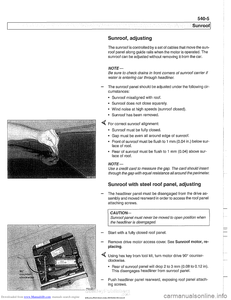
For correct sunroof alignment:
Sunroof must be fully closed.
Gap must be even all around edge of sunroof.
Front of sunroof must be flush to
1 mm (0.04 in.) below sur-
face of roof.
. Rear of sunroof must be flush to 1 mm (0.04) above sur-
face of roof.
NOTE-
Use a credit card to measure the gap. The card sllould insert
through the gap with equal resistance all around the perimeter.
Sunroof with steel roof panel, adjusting
- The headliner panel must be disengaged from the drive as-
sembly and moved rearward in order to access the roof panel
attaching screws.
CAUTIOI\C
Sunroof panel must never be moved to open position when . .
I the headliner is disenaaaed. 1
- Start with a fully closed roof panel.
- Remove drive motor access cover. See Sunroof motor, re-
placing.
Using hex key from tool kit, turn motor drive 90" counter-
clockwise.
Rear of sunroof panel will drop
2 to 3 mm (0.08 to 0.12 in).
This disengages headliner from sunroof panel.
- Push headliner panel rearward, exposing roof panel attach-
ing screws.