four BMW 525i 1999 E39 Workshop Manual
[x] Cancel search | Manufacturer: BMW, Model Year: 1999, Model line: 525i, Model: BMW 525i 1999 E39Pages: 1002
Page 8 of 1002
Downloaded from www.Manualslib.com manuals search engine
I General Warnings and Cautions
WARNINGS (continued)
. The air conditioning system is filled with chemical refrigerant,
which is hazardous. The AIC system should be serviced only by
trained technicians using approved refrigerant recoverylrecycling
equipment, trained in related safety precautions, and familiar with
regulations governing the discharging and disposal of automotive
chemical refrigerants.
. Do not expose any part of the AIC system to high temperatures
such as open flame. Excessive heat will increase system pres-
sure and may cause the system to burst.
Some aerosol tire inflators are highly flammable. Be extremely
cautious when repairing a tire that may have been inflated using
an aerosol tire inflator. Keep sparks, open flame or other sources
of ignition away
from the tire repair area. Inflate and deflate the
tire at least four
times before breaking the bead from the rim.
Completely remove the tire from the rim before attempting any re-
pair.
Cars covered by this manual are equipped with a supplemental
restraint system (SRS), that automatically deploys
airbags and
pyrotechnic seat belt tensioners
In the event oi a frontal or side
impact. These are explosive devices. Handled improperly or with-
out adequate safeguards, they can be accidently activated and
cause serious injury.
- The ignition system produces high voltages that can be fatal.
Avoid contact with exposed terminals and use extreme care when
working on a car with the engine running or the ignition switched
on.
. Place jack stands only at locations specified by the manufacturer.
The vehicle
illtino iack su~olied with the vehicle is intended fortire -. , . changes only. A heavy duty floor jack should be used lo lift vehicle
before installing
jacl( stands. See 010 General.
- Battery acid (electrolyte) can cause severe burns. Flush contact
area
with water, seek medical attention.
Aerosol cleaners and solvents may contain hazardous or deadly
vapors and are highly flammable. Use only in a well ventilated ar-
ea. Do not use on hot surfaces (engines, brakes, etc.).
Do not remove
coolant reservoir or radiator cap with the engine
hot. Danger of burns and engine damage.
CAUTIONS-
See also WARNINGS
- if you lack the slqills, tools and equipment, or a suitable worl(shop
for any procedure described in this manual, leave such repairs to
an authorized BMW dealer or other qualified shop.
BMW is constantly improving its cars and sometimes these
changes, both in parts and specifications, are made applicable to
earlier models. Therefore, part numbers listed in this manual are
for reference only. Always check with your authorized BMW deal-
er parts department for the latest information.
Before starting a job, make certain that you have all the neces-
sary tools and parts on hand. Read ail the instructions thorough-
ly, and do not attempt shortcuts. Use tools appropriate to the
work and use only replacement parts meeting BMW specifica-
tions.
Use pneumatic and electric tools only to loosen threaded parts
and fasteners. Never use these tools to tighten fasteners, espe-
cially on light alloy parts. Always use a torque wrench to tighten
fasteners to the tightening torque specification listed.
Be mindful of the environment and ecology. Before you drain the
crankcase, find out the proper way to dispose of the
oil. Do not
pour
oil onto the ground, down a drain, or into a stream, pond or
lake. Dispose of waste in accordance with Federal, State and
Local laws.
The control module for the anti-lock brake system
(ABS) cannot
withstand temperatures from a paint-drying booth or a heat
lamp
in excess of 203" F (95°C) and should not be subjected to tem-
peratures in excess of 185°F
(8S°C) for more than two hours.
- Before doing any electrical welding on cars equipped with ABS,
disconnect the battery negative
(-) terminal (ground strap) and
the ABS control module connector.
- Always make sure ignition is off before disconnecting battery.
Label battery cables before disconnecting. On some models, bat-
tery cables are not color coded.
Disconnecting the battery may erase fault code@) stored in control
module memory. Using special BMW diagnoslic equipment, check
lor
iauit codes prior to disconnecting the battery cables. If the mal-
I.mct on ndicator Ignt (MIL) s I. ..minaled. see OBD On-Board
Diaanostics
Tl11s iant is iuenlfted as lne Check Ena~ne oht
(1997-2000 models jor~ervlce Engine Soon light (2061 andlater
models). If any other system iaults have been detected (indicated
by an illuminated warning light), see an authorized BMW dealer.
If a normal
or rapid charger is used to charge battery, the battery
must be disconnected and removed from the vehicle in order to
avoid damaging the vehicle.
- Do not quick-charge the battery (for boost starting) for longer
than one minute. Wait at least one minute before boosting the
battery a second time.
* Connect and disconnect a battery charger only with the battery
charger switched off.
- Sealed or "maintenance free" batteries should be slow-charged
only, at an amperage rate that is approximately 10% of the bat-
tery's ampere-hour (Ah)
rating.
. Do not allow battery charging voltage to exceed 16.5 volts. If the
battery begins producing gas or boiling violently, reduce the
charging rate.
Boosting a sulfated battery at a high charging rate
can cause an explosion.
Page 15 of 1002
Downloaded from www.Manualslib.com manuals search engine
General
Much of the necessary maintenance and minor repairthat an
automobile will need can be done with ordinary tools. Below
you'll find important information on how to work safely, a dis-
cussion of what tools will be needed and how to use them.
Safety
Although an automobile presents many hazards, common
sense and good equipment can help ensure safety. Many ac-
cidents happen because of carelessness. Pay attention and
stick to the safety rules in this manual.
Lifting the car
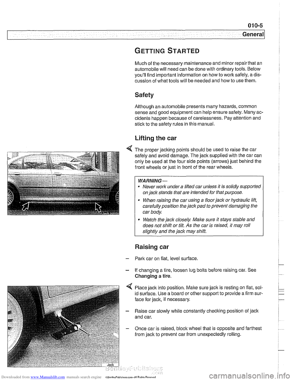
4 The proper jacking points should be used to raise the car
safely and avoid damage. The
jack supplied with the car can
only be used at the four side points (arrows) just behind the
front wheels or just in front of the rear wheels.
WARNING-
. Never work under a lifted car unless it is solidly supported
on
jack stands that are intended for that purpose.
When raising the car using a floorjack or hydraulic lift,
carefully position the jack pad to prevent damaging the
car body.
* Watch the jack closely. Male sure it stays stable and
does not shift or tilt.
As the car is raised, it may roll
sliahtlv and the
jack mav shift.
Raising car
- Park car on flat, level surface.
- If changing a tire, loosen lug bolts before raising car. See
Changing
a tire.
Place jack into position.
Malte sure jack is resting on flat, sol-
id surface. Use a board or other support to provide a firm sur-
face for jack, it necessary.
- Raise car slowly while constantly checking position of jack
and car.
- Once car is raised, bloclc wheel that is opposite and farthest
from jack to prevent car from unexpectedly rolling.
Page 30 of 1002
Downloaded from www.Manualslib.com manuals search engine
01 0-20
General
more information on the Check Engine Light and the on-
board diagnostic system.
Towing
The cars covered by this manual should be towed with a tow
truck using wheel lift or flat bed equipment. Do not tow the car
on all four wheels except
forvery short distances to move it to
a safe place.
CA U JION-
Do not tow with sling-type equipment The front spoilers and
b~m~er covers may sustain damage.
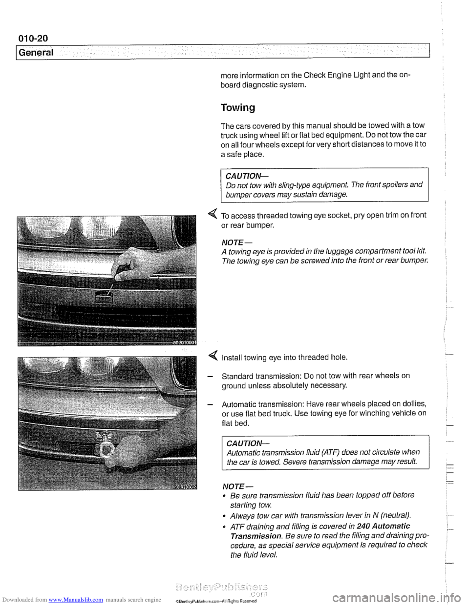
4 To access threaded towing eye socltet, pry open trim on front
or rear bumper.
NOJE-
A towing eye is provided in the luggage compartment tool lcit.
The towing eye can be screwed into the front or rear bumper.
4 Install towing eye into threaded hole.
- Standard transmission: Do not tow with rear wheels on
ground unless absolutely necessary.
- Automatic transmission: Have rear wheels placed on dollies,
or use flat bed truck. Use towing eye for winching vehicle on
flat bed.
CAUTION-
Automatic transmission fluid (ATF) does not circulate when
I the car is towed. Severe transmission damage may result.
NOTE-
Be sure transrnission fluid has been topped off before
starting tow.
Always tow car with transrnission lever in
N (neutral).
. ATF draining and filling is covered in 240 Automatic
Transmission.
Be sure to read the filling and draining pro.
cedure, as special service equipment is required to
checlc
the fluid level.
Page 48 of 1002
Downloaded from www.Manualslib.com manuals search engine
020-1 6
Maintenance
loose, hose is damaged, or connection is dirty or corroded.
Dried coolant has achalky appearance. Hoses should be firm
and springy. Replace any hose that is cracked, has become
soft and limp, or has been contaminated by oil.
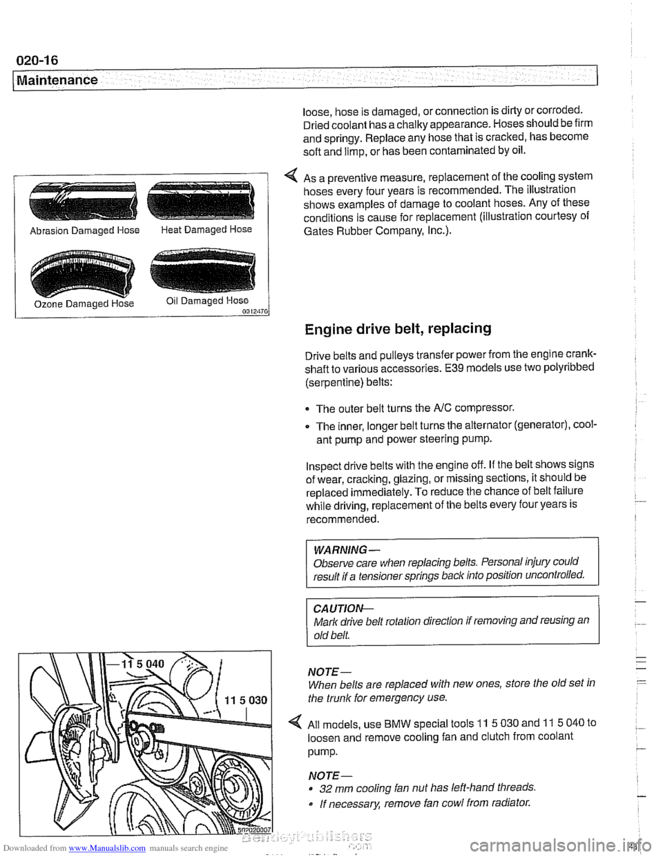
4 As a preventive measure, replacement of the cooling system
hoses every four years is recommended. The illustration
shows examples of damage to coolant hoses. Any of these
conditions is cause for replacement (illustration courtesy of
/ Abrasion Damaged Hose Heat Damaged Hose 1 Gates Rubber Company, I~c.).
Engine drive belt, replacing
Drive belts and pulleys transfer power from the engine crank-
shaft to various accessories.
E39 models use two polyribbed
(serpentine) belts:
The outer belt turns the
NC compressor.
0 The inner, longer belt turns the alternator (generator), cool-
ant pump and power steering pump.
Inspect drive belts with the engine off. If the belt shows signs
of wear, cracking, glazing, or missing sections, it should be
replaced
immediately. To reduce the chance of belt failure
while driving, replacement of the belts every four years is
recommended.
WARNING -
Observe care when replacing belts. Personal injury could
result if a tensioner springs back into position uncontrolled.
CA UTIOI\C
Mark drive belt rotation direction if removing and reusing an
old belt.
NOTE-
When belts are replaced with new ones, store the old set in
the trunk for emergency use.
All models, use
BMW special tools 11 5 030 and 11 5 040 to
loosen and remove cooling fan and clutch from coolant
pump.
NOTE-
32 mm cooling fan nut has left-hand threads
If necessary, remove fan cowl from radiator.
Page 52 of 1002
Downloaded from www.Manualslib.com manuals search engine
Maintenance
continue to operate as designed. Extending the replacement
interval may void the emission control warranty coverage.
See
180 Exhaust System for information on replacing the
oxygen sensors.
Tightening torque
Oxvoen sensor to exhaust
manifold 50 Nrn (37 ft-lb)
NOTE-
A special soclet for replacing the oxygen sensor is available
from most automotive parts stores. The soclet has
a groove
cut down one side to allow the sensor to be installed without
damaging the wire harness.
Power steering fluid, checking level
The power steering system is permanently filled and does not
have a drain. Routinely adding ATF is not required unless the
system is leaking.
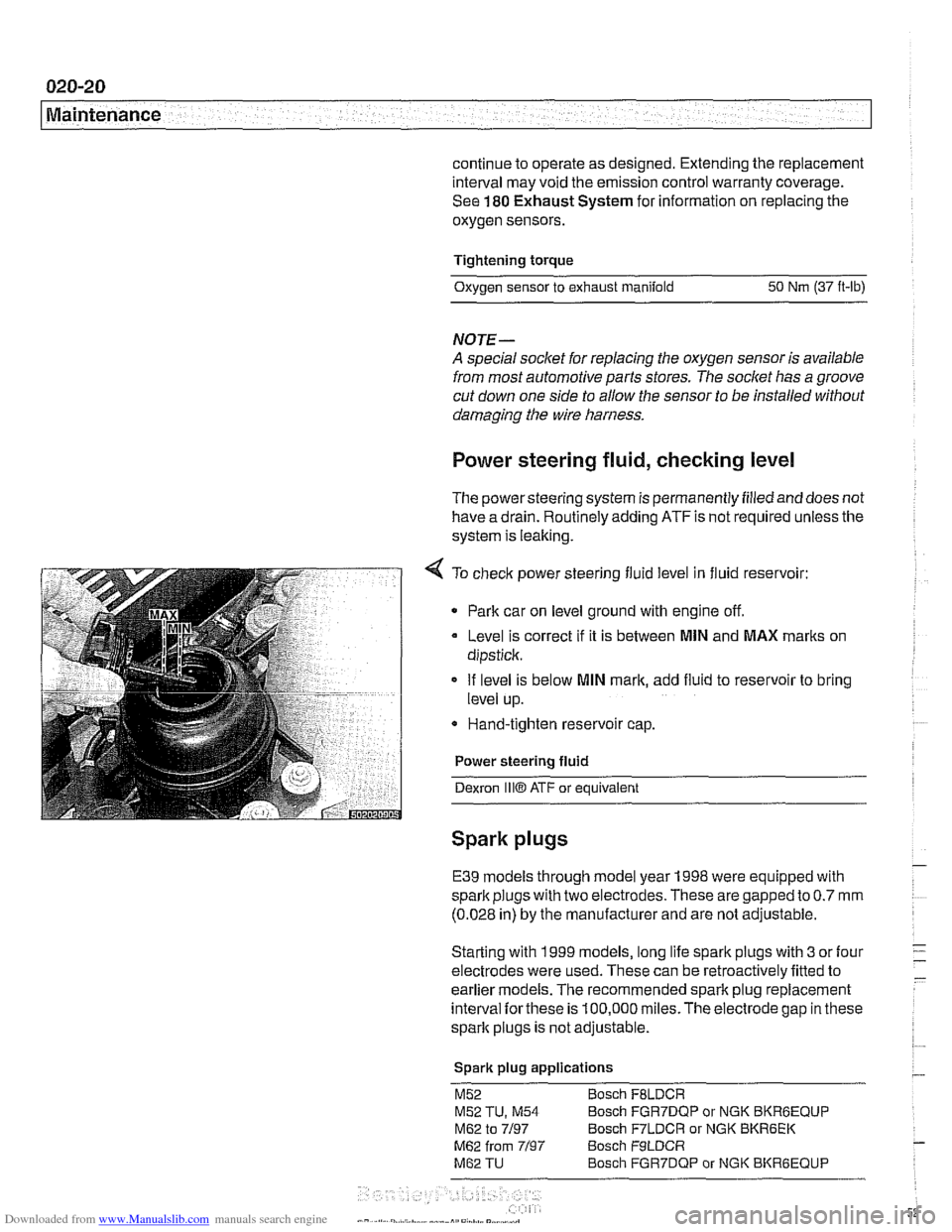
4 To check power steering fluid level in fluid reservoir:
Park car on level ground with engine off.
Level is correct
if it is between MlN and MAX marks on
dipstick.
If level is below
MlN mark, add fluid to reservoir to bring
level up.
* Hand-tighten reservoir cap.
Power steering fluid
Dexron
1iiO ATF or equivalent
Spark plugs
E39 models through model year 1998 were equipped with
spark plugs with two electrodes. These are gapped to
0.7 mm
(0.028 in) by the manufacturer and are not adjustable.
Starting with 1999 models, long life spark plugs with
3 or four
electrodes were used. These can be retroactively fitted to
earlier
models. The recommended spark plug replacement
interval
forthese is 100,000 miles.The electrode gap in these
spark plugs is not adjustable.
Spark plug applications
M52 Bosch FBLDCR
M52 TU, M54 Bosch FGR7DQP or NGK BKRBEQUP
M62 to 7/97 Bosch F7LDCR or NGK BKR6EK
M62 from 7/97 Bosch F9LDCR
M62 TU Bosch FGR7DQP or NGK BKRGEQUP
Page 56 of 1002
Downloaded from www.Manualslib.com manuals search engine
020-24
Maintenance
tions. In general, replacement batteries should always be
rated equal or higher than the original battery.
The battery is held in place by a single hand screw and plate.
A secure battery hold-down is important in order to prevent
vibrations and road shoclt from damaging the battery.
CAUTION-
Prior to disconnecting the baitem read the battery discon-
nection cautions given in
001 General Cautions and
Warnings.
NOTE-
Always disconnect the negative (-) cable first, and connect
it last. While changing the battery, clean away any corro-
sion in or around the battery tray
More battery and charging system information is in 121
Battery, Alternator, Starter.
Brake fluid, replacing
Brake fluid absorbs moisture easily, and moisture in the fluid
affects bralte performance and reliability. This is why
BMW
strictly recommends replacing the bralte fluid every two
years. When replacing or adding bralte fluid, use only new
fluid from previously unopened containers. Do not use brake
fluid that has been bled from the system, even
if it is brand
new. Use only DOT
4 brake fluid.
NOTE-
See 340 Brakes for brake fluid flushing procedures.
Brake pad 1 rotor wear, checking
Disc brakes are fitted at all four wheels. Although the brakes
are equipped with a brake pad warning system, the system
only monitors one wheel per axle. Pad thickness should be
checked whenever wheels are off or brake
worlt is being
done.
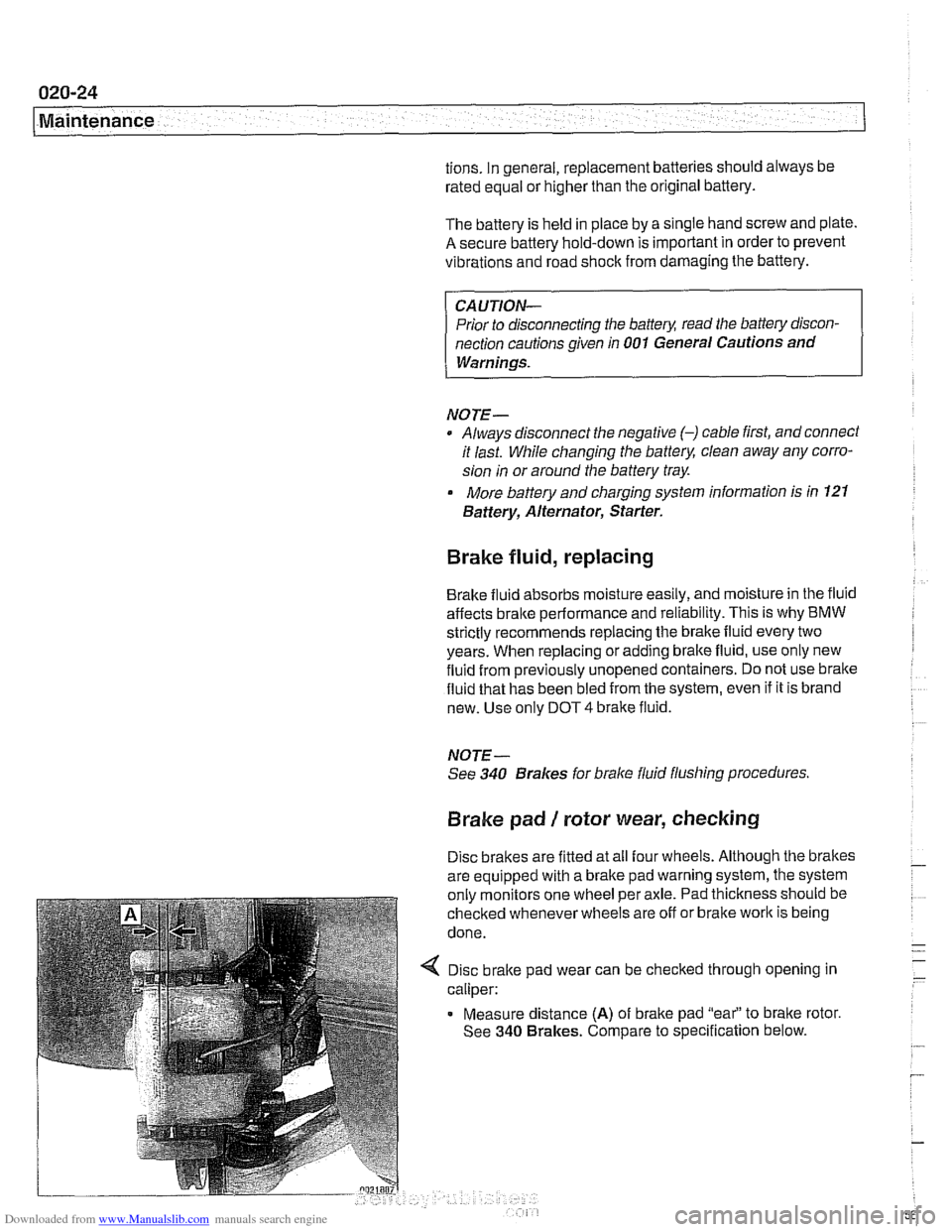
4 Disc brake pad wear can be checked through opening in
caliper:
Measure distance
(A) of brake pad "eai' to bralte rotor.
See
340 Brakes. Compare to specification below.
Page 70 of 1002
Downloaded from www.Manualslib.com manuals search engine
100-4
I Engine-General
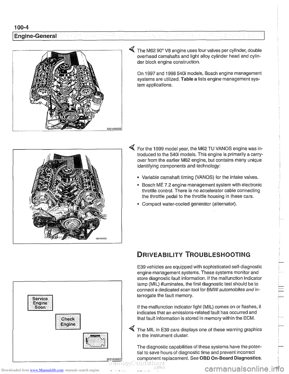
The M62 90" V8 engine uses four valves per cylinder, double
overhead camshafts and light alloy cylinder head and cylin-
der
bloclc engine construction.
On 1997 and 1998 540i models, Bosch engine management
systems are utilized. Table a lists engine management sys-
tem applications.
4 For the 1999 model year, the M62 TU VANOS engine was in-
troduced to the 540i models. This engine is primarily a carry-
over from the earlier M62 engine, but contains many unique
identifying components and technology:
Variable camshaft timing (VANOS) for the intake valves.
Bosch ME 7.2 engine management system with electronic
throttle control. There is no accelerator cable connecting
the throttle pedal to the throttle housing in these cars.
Compact water-cooled generator (alternator).
E39 vehicles are equipped with sophisticated self-diagnostic
engine management systems. These systems monitor and
store diagnostic fault information. If the malfunction indicator
lamp (MIL) illuminates, the first diagnostic test should be to
connect a dedicated scan tool for BMW automobiles and in-
terrogate the fault memory.
If the malfunction indicator light (MIL) comes on orflashes, it
indicates that an emissions-related fault has occurred and
that fault information is stored in memory within the ECM.
4 The MIL in E39 cars displays one of these warning graphics
in the instrument cluster.
The diagnostic capabilities of these systems have the poten-
tial to save hours of diagnostic time and prevent incorrect
5 placement. See OBD On-Board Diagnostics.
Page 250 of 1002
Downloaded from www.Manualslib.com manuals search engine
I Camshaft Timing Chain
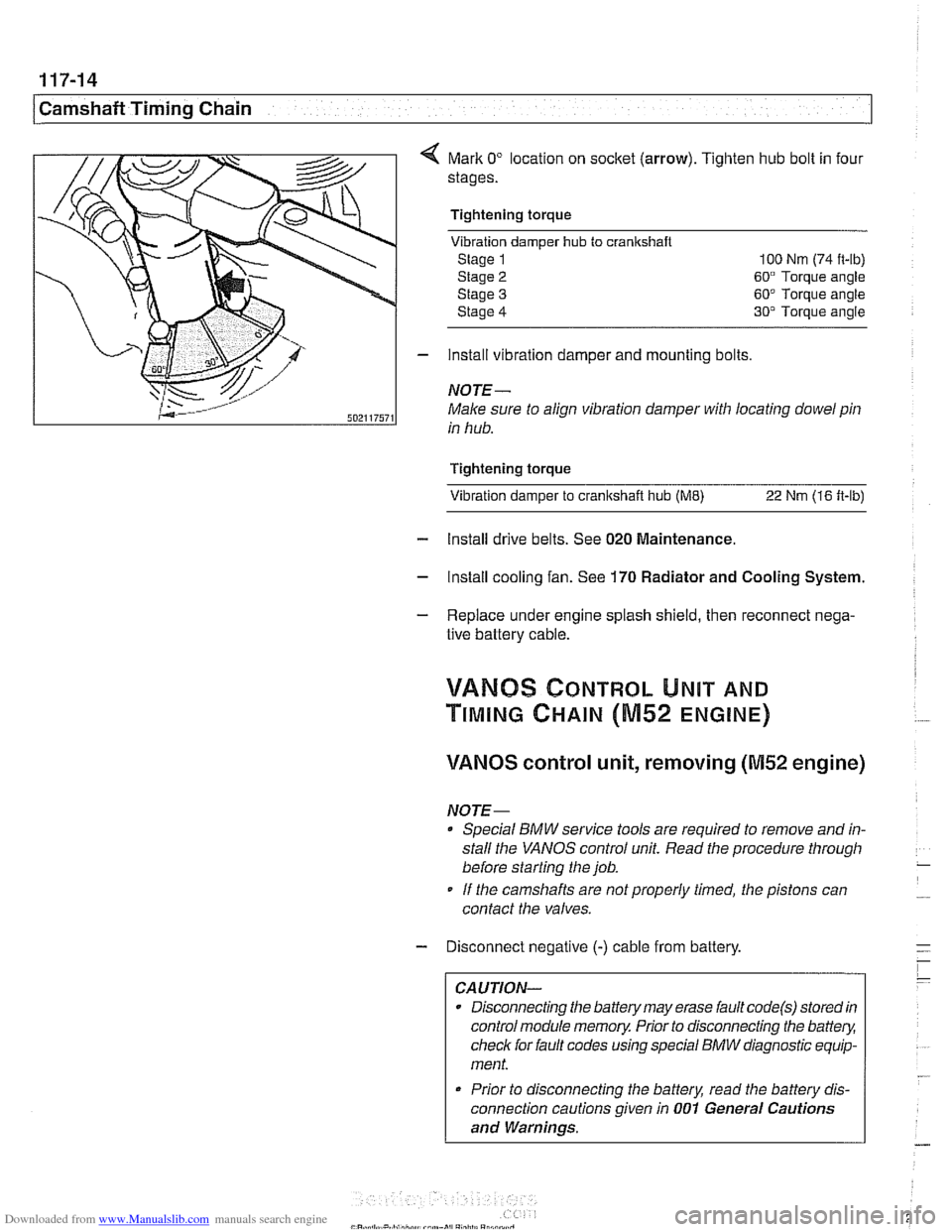
Mark 0" location on socket (arrow). Tighten hub bolt in four
stages.
Tightening torque Vibration damper
hub to cranlrshaft
Stage 1 100 Nm (74 it-lb)
Stage
2 60" Torque angle
Stage
3 60" Torque angle
Stage
4 30" Torque angle
- install vibration damper and mounting bolts
NOTE-
Male sure to align vibration damper with locating dowel pin
in hub.
Tightening torque Vibration damper to
cranltshait hub (ME) 22 Nm (16 ft-lb)
- Install drive belts. See 020 Maintenance.
- Install cooling fan. See 170 Radiator and Cooling System.
- Replace under engine splash shield, then reconnect nega-
tive battery cable.
!/ANBS CONTROL UNIT AND
TIMING CHAIN (M52 ENGINE)
VANOS control unit, removing (M52 engine)
NOTE-
Special BMW service tools are required to remove and in-
stall the
VANOS control unit. Read the procedure through
before starting the job.
If the camshafts are notproperly timed, the pistons can
contact the valves.
- Disconnect negative (-) cable from battery.
CAUTION-
Disconnecting the battery may erase fault code(s) stored in
control module memory. Prior to disconnecting the
battev,
check for fault codes using special BMW diagnostic equip-
ment.
* Prior to disconnecting the battery, read the battery dis-
connection cautions given in
001 General Cautions
and Warnings.
Page 353 of 1002
Downloaded from www.Manualslib.com manuals search engine
Lnition switch
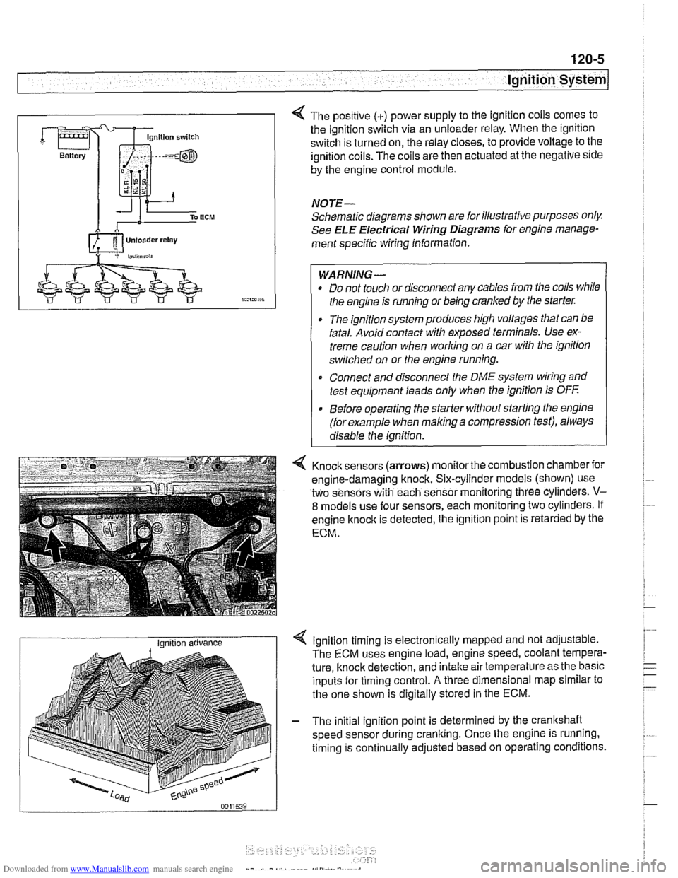
4 The positive (+) power supply to the ignition coils comes to
the ignition switch via an unloader relay. When the ignition
switch is turned on, the relay closes, to provide voltage to the
ignition coils. The coils are then actuated at the negative side
by the engine control module.
NOTE-
Schematic diagrams shown are for illustrative purposes only.
See ELE Electrical Wiring Diagrams for engine manage-
ment specific wiring information.
WARNING- Do not touch or disconnect any cables from the coils while
the engine is running or being cranked by the starter:
The ignition system produces high voltages that can be
fatal. Avoid contact with exposed terminals. Use ex-
treme caution when
working on a car with the ignition
switched on or the engine running.
* Connect and disconnect the DME system wiring and
test equipment leads only when the ignition is
OFF
Before operating the starter without starting the engine
(for example when
making a compression test), always
disable the ignition.
4 Knock sensors (arrows) monitor the combustion chamber for
engine-damaging knock. Six-cylinder models (shown) use
two sensors with each sensor monitoring three cylinders.
V-
8 models use four sensors, each monitoring two cylinders. If
engine
knock is detected, the ignition point is retarded by the
ECM.
I Ignition advance Ignition timing is electronically mapped and not adjustable.
The ECM uses engine load, engine speed, coolant tempera-
ture, knock detection, and intake air temperature as the basic
inputs for timing control.
A three dimensional map similar to
the one shown is digitally stored in the ECM.
- The initial ignition point is determined by the crankshaft
speed sensor during cranking. Once the engine is running.
timing is continually adjusted based on operating conditions.
Page 462 of 1002
Downloaded from www.Manualslib.com manuals search engine
130-72
Fuel Injection
I Oxygen sensors, replacing
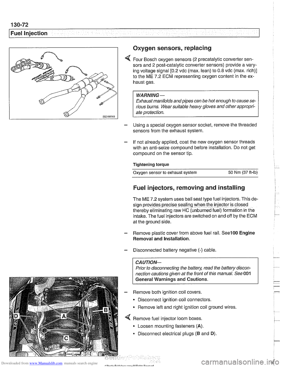
4 Four Bosch oxygen sensors (2 precatalytic converter sen-
sors and
2 post-catalytic converter sensors) provide a vary-
ing voltage signal
[0.2 vdc (max. lean) to 0.8 vdc (max. rich)]
to the ME
7.2 ECM representing oxygen content in the ex-
haust gas.
WARNING-
Exhaust manifolds and pipes can be hot enough to cause se-
rious burns. Wear suitable heavy gloves and other appropri-
ate protection.
- Using a special oxygen sensor socltet, remove the threaded
sensors from the exhaust system.
- If not already applied, coat the new oxygen sensor threads
with an anti-seize compound before installation. Do not get
compound on the sensor tip.
Tightening torque
Oxygen sensor to exhaust system
50 Nm (37 ft-lb)
Fuel injectors, removing and installing
The ME 7.2 system uses ball seat type fuel injectors. This de-
sign
prov:des precise seal'ng when the iniector is closed
therebv eiminalinq raw HC (unb~rned fue ) formalion in tne
intake.-~he fuel inkctors areswitched on and off by the ECM
at the ground side.
- Remove plastic cover from above fuel rail. See100 Engine
Removal and Installation.
- Disconnected battery negative (-) cable.
CAUTION-
Prior to disconnecting the battea read the battery discon-
nection cautions given at the front of this manual. See 001
General Warnings and Cautions.
- Remove both ignition coil covers.
Disconnect ignition coil connectors.
Remove left and right ignition coil ground wires,
4 Remove fuel injector loom boxes.
Loosen mounting fasteners
(A).
Disconnect electrical plugs (B and D).