four BMW 525i 1999 E39 User Guide
[x] Cancel search | Manufacturer: BMW, Model Year: 1999, Model line: 525i, Model: BMW 525i 1999 E39Pages: 1002
Page 580 of 1002
Downloaded from www.Manualslib.com manuals search engine
Manual Transmission
- Thoroughly clean guide sleeve mounting bolts, sealing sur-
faces, and threads. Apply
Loctite8243 or equivalent thread
locking compound to guide sleeve bolts. Reinstall guide
sleeve and
spacer(s).
Tightening torques
Guide sleeve to transmission case
M6 10 Nm (89 in-lb)
* M8 x 22 18 Nm (13 ft-lb)
- Max30 25 Nm (18 ft-lb)
- Reinstall transmission.
TRANSMISSION REMOVAL AND
~NSTALLATION
Removal and installation of the transmission is best accorn-
plished on a lifl using a transmission jack.The engine must be
supported using appropriate support equipment. This allows
the engine to pivot on its mounts to access the upper
Torx-
head bolts at the bellhousing.
WARNING-
Male sure the car is stable and well supported at all times.
Use a professional aulomorive lift or jack slanos des~gned
lor the purpose. A floor jack is nor adequare supporr.
The removal of the transmission may upset the balance
of the vehicle on a
lifl.
Transmission, removing and installing
- Disconnect negative (-) cable from battery.
CAUTION-
Prior to disconnecting the battery, read the battery discon-
nection cautions given
in 001 Warnings and Cautions.
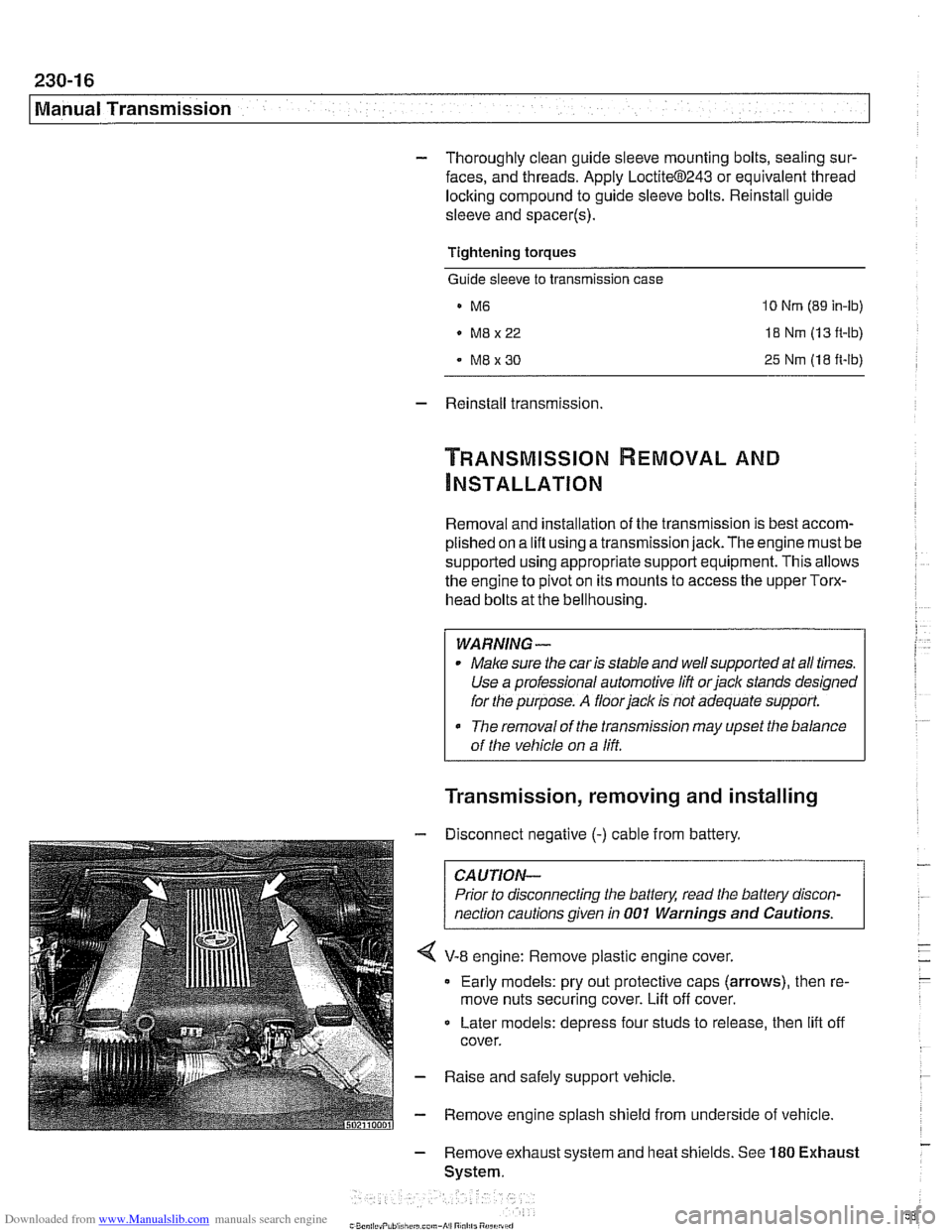
V-8 engine: Remove plastic engine cover.
Early models: pry out protective caps (arrows), then re-
move nuts securing cover. Lift off cover.
Later models: depress four studs to release, then
lift off
cover.
- Raise and safely support vehicle
- Remove engine splash shield from underside of vehicle
- Remove exhaust system and heat shields. See 180 Exhaust
System.
Page 594 of 1002
Downloaded from www.Manualslib.com manuals search engine
240-1 0
Automatic Transmission
TRANSMISSION REMOVAL AND
INSTALLATION
Removal and installation of the transmission is best accorn-
plished on an automotive lift using a transmission jack. Use
caution and safe workshop practices when working beneath
car and lowering transmission.
Torx-head bolts are used to mount the transmission to the
bellhousing.
Besure to have appropriate tools on hand before
starting the job.
WARNING-
Be sure the vehicle is properly supported. The removal of the
transmission may upset the balance of the vehicle on a lift
CAUJION-
Tilting the engine to remove the transmission can lead to
damaae to various components due to
laclc of clearance. 1
Transmission, removing and installing
WARNING -
Allow engine and transmission to cool down before starting
work on the transmission.
- Disconnect negative (-) cable from battery.
CAUTION-
Prior to disconnecting the battery, read the battery discon-
nection cautions given in
001 General Cautions and
Warninas.
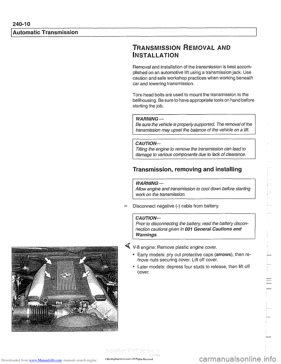
4 V-8 engine: Remove plastic engine cover.
Early models: pry out protective caps
(arrows), then re-
move nuts securing cover.
Lift off cover.
Later models: depress four studs to release, then lift off
cover.
Page 657 of 1002
Downloaded from www.Manualslib.com manuals search engine
31 0-21
Front Suspension
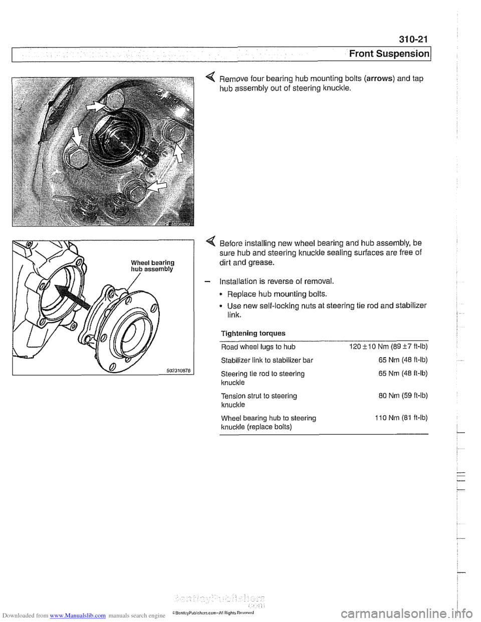
4 Remove four bearing hub mounting bolts (arrows) and tap
hub assembly out of steering knuckle.
4 Before installing new wheel bearing and hub assembly, be
sure hub and steering knuckle sealing surfaces are free of
dirt and grease.
- Installation is reverse of removal.
Replace hub mounting bolts.
Use new self-locking nuts at steering tie rod and stabilizer
link.
Tightening
torques
Road wheel lugs to hub 120i-10 Nm (89i-7ft-lb)
Stabilizer link to stabilizer bar
Steering tie rod to steering
ltnuckle
Tension strut to steering
knucltie
Wheel bearing hub to steering
Itnucltle (replace bolts)
65 Nm (48 ft-lb)
65
Nm (48 it-lb)
80 Nm (59 ft-lb)
1
lo Nm (81 ft-lb)
Page 691 of 1002
Downloaded from www.Manualslib.com manuals search engine
Steerina and Wheel ~lianmentl
Proper handling, stability and driving ease depend upon the
correct alignment of all four wheels. The front axle is aligned
in relation to the rear axle, then the front wheels are aligned in
relation to one another. This is known as a four-wheel or
thrust-axis alignment.
Front and rear alignment specification are given in tables at
the end of this repair group.
BMW E39 cars use a sophisticated multi-link suspension at
the front and rear of the car. Proper alignment requires com-
puterized alignment equipment.
Camber
Front wheel camber is set at the factory and cannot be adjust-
ed. Rear wheel camber is fully adjustable.
Always set rear camber before adjusting toe
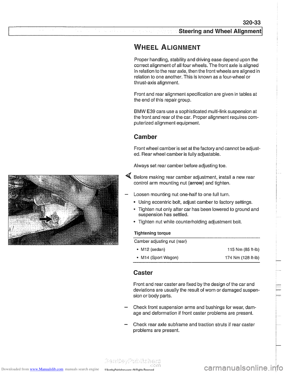
Before making rear camber adjustment, install a new rear
control arm mounting nut
(arrow) and tighten.
- Loosen mounting nut one-half to one full turn.
Using eccentric bolt, adjust camber to factory settings.
Tighten nut only after car has been lowered to ground and
suspension has settled.
Tighten nut while counterholding adjustment bolt.
Tightening torque
Camber adjusting nut (rear)
MI2 (sedan)
- MI4 (Sport Wagon)
115 Nm (85 ft-lb)
174 Nm (128 ft-lb)
Caster
Front and rear caster are fixed by the design of the car and
deviations are usually the result of worn or damaged suspen-
sion or body parts.
- Check front suspension arms and bushings for wear, dam-
age and deformation if front caster problems are present.
- Check rear axle subfrarne and traction struts if rear caster
problems are present.
Page 736 of 1002
Downloaded from www.Manualslib.com manuals search engine
330-40
Rear Suspension
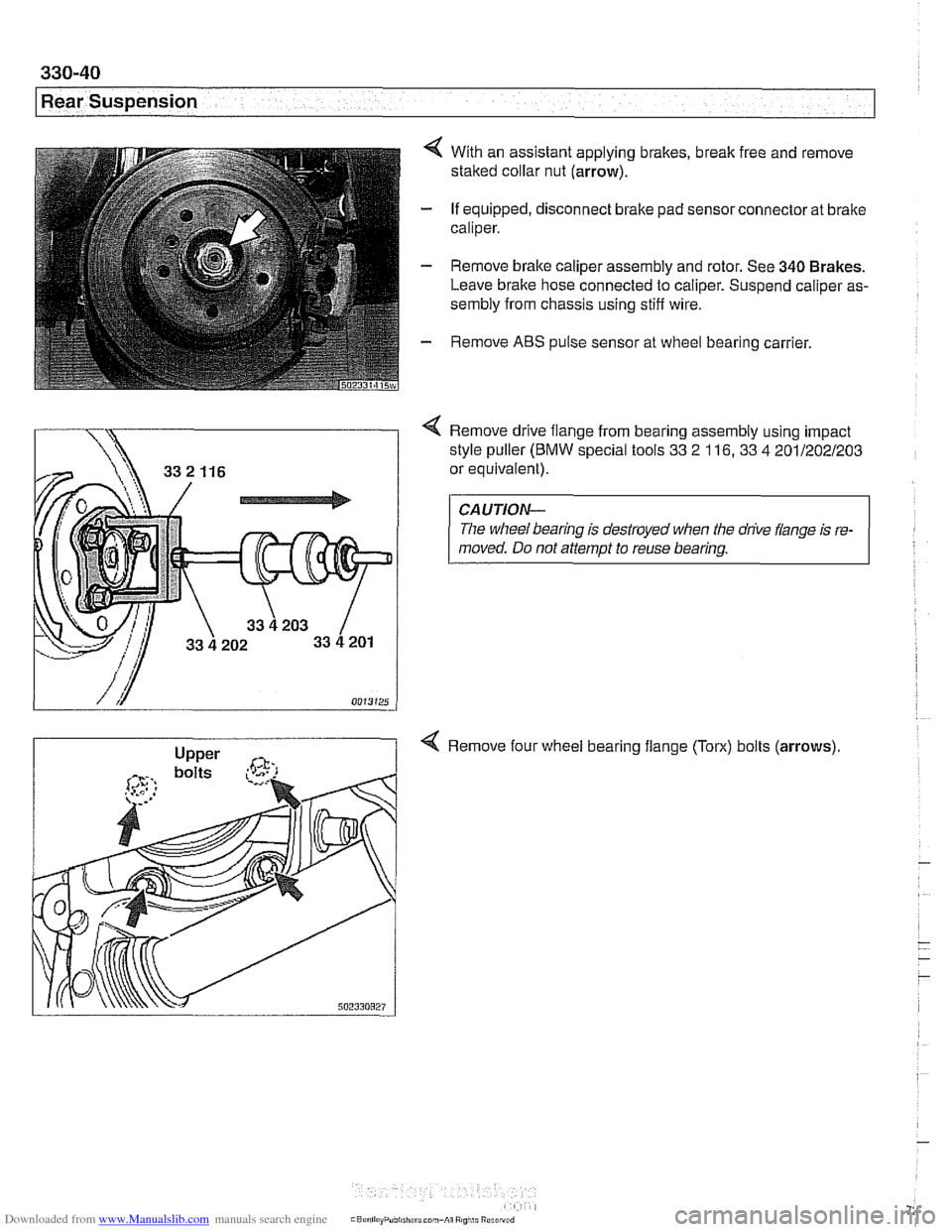
4 With an assistant applying brakes, break free and remove
staked collar nut (arrow).
- If equipped, disconnect brake pad sensor connector at brake
caliper.
- Remove brake caliper assembly and rotor. See 340 Brakes.
Leave brake hose connected to caliper. Suspend caliper as-
sembly from chassis using stiff wire.
- Remove ABS pulse sensor at wheel bearing carrier.
Remove drive flange from bearing assembly using impact
style puller
(BMW special tools 33 2 116, 33 4 201/202/203
or equivalent).
CAUTION-
The wheel bearing is destroyed when the drive flange is re-
moved. Do not attempt to reuse bearing.
4 Remove four wheel bearing flange (Torx) bolts (arrows)
Page 766 of 1002
Downloaded from www.Manualslib.com manuals search engine
E39 brake system
BMW E39 models are equipped with vacuum power-assisted
four-wheel disc brakes with an integral
Antilock Brake System
(ABS). Single-piston calipers act on vented front and rear ro-
tors. A brake pad wear sensor for each axle indicates when
brake pads need replacement. The dual drum-type parking
brake system is integrated with the rear brake rotors.
Electronic braking and stability control
E39 models were introduced with Automatic Stability Control,
a computer controlled traction control system that uses the
AB5 system in conjunction with engine management controls
to control wheel spin during take-off and maintain vehicle sta-
bility while braking.
Added in the
1998 model year was Dynamic Stability Control
(DSC). This system implements wheel speed modulation
throughout all stages of driving. For example, DSC is able to
reduce understeer by applying differing amounts of braking
force to each wheel, or it can override the engine manage-
ment system during hard cornering.
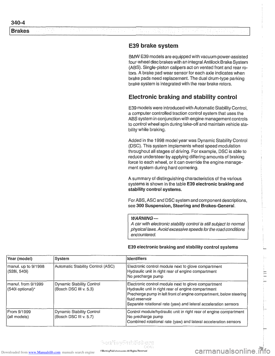
A summary of distinguishing characteristics of the various
systems is shown in the table
E39 electronic braking and
stability control systems.
For ABS, ASC and DSC system and component descriptions,
see
300 Suspension, Steering and Brakes-General.
WARNING-
A car with electronic stability control is still subject to normal
physical laws. Avoid excessive speeds for the road conditions
encountered.
E39 electronic braking and stability control systems
Year (model)
manuf. up to 911998
(528i, 540i)
manuf. from 911999
(540i optional)*
From
911 999
(ail models) System
Automatic Stability Control (ASC) Identifiers
Electronic control module next to glove compartment
Hydraulic unit in right rear of engine compartment
No precharge pump
Dynamic Stability Control
(Bosch DSC
Ill v. 5.3)
Dynamic
Stabil~ty Control
(Bosch DSC
Ill v. 5.7) Electronic
control module next to glove compartment
Hydraulic unit in right rear of engine compartment
Precharge pump in left front of engine compartment, below steering
fluid reservoir
Separate rotational rate (yaw) and lateral acceleration sensors
Control
modulelhydraulic unit in right rear of engine compartment
No precharge pump
Combined rotational rate (yaw) and lateral acceleration sensors
Page 803 of 1002
Downloaded from www.Manualslib.com manuals search engine
400-9
Body-General
Battery safety terminal
(BST)
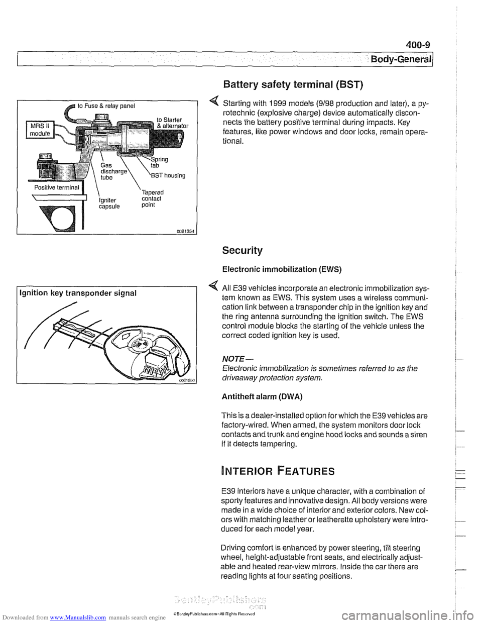
4 Starting with 1999 models (9198 production and later), a py-
rotechnic (explosive charge) device automatically discon-
nects the battery positive terminal during impacts. Key
features,
like power windows and door locks, remain opera-
tional.
Security
Electronic immobilization (EWS)
Ignition key transponder signal All
E39 vehicles incorporate an electronic immobilization sys-
tem known as EWS. This svstem uses a wireless comrnuni-
cation link between a transponder chip in the ignition key and
the ring antenna surrounding the ignition switch. The EWS
control module blocks the starting of the vehicle unless the
correct coded ignition key is used.
NOTE-
Electronic immobilization is sometimes referred to as the
driveaway protection system.
Antitheft alarm (DWA)
This is adealer-installed option for which the E39 vehicles are
factory-wired. When armed, the system monitors door
loci(
contacts and trunk and engine hood locks and sounds a siren
if it detects tampering.
E39 interiors have a unique character, with a combination
of
sporty features and innovativedesign. All body versions were
made in a wide choice of interior and exterior colors. New col-
ors with matching leather or leatherette upholstery were intro-
duced for each model year.
Driving
comfort is enhanced by power steering, tilt steering
wheel, height-adjustable front seats, and electrically adjust-
able and heated rear-view mirrors. Inside the car there are
reading lights at four seating positions.
Page 853 of 1002
Downloaded from www.Manualslib.com manuals search engine
-.- -
Exterior Trim, Bumpers
Outside mirror glass with automatic dip control,
replacing
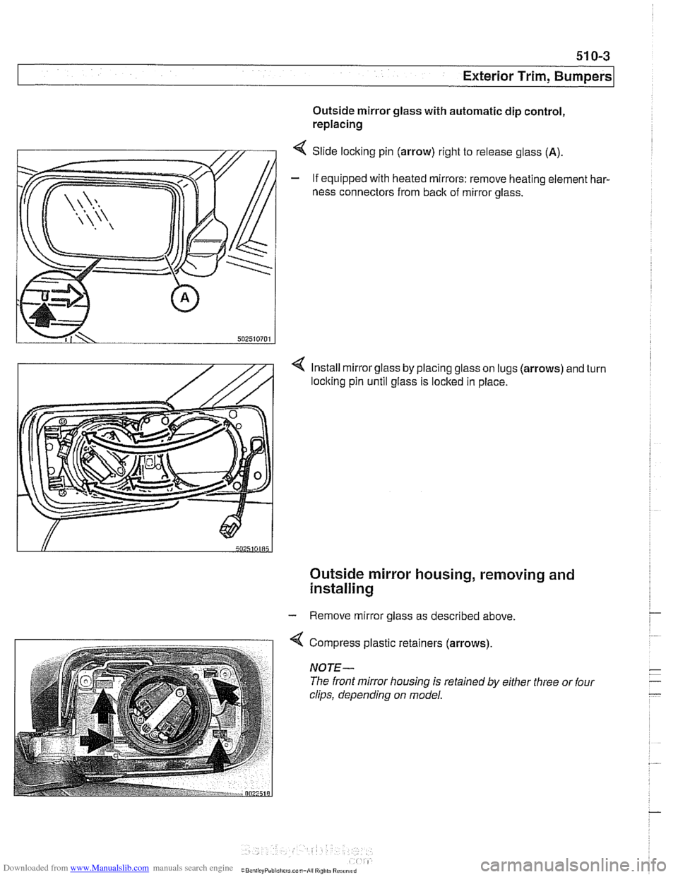
4 Slide locking pin (arrow) right to release glass (A).
- If equipped with heated mirrors: remove heating element har-
ness connectors from
back of mirror glass.
4 Install mirror glass by placing glass on lugs (arrows) and turn
loclting pin until glass is locked in place.
Outside mirror housing, removing and
installing
- Remove mirror glass as described above.
4 Compress plastic retainers (arrows)
NOTE-
The front mirror housing is retained by either three or four
clips, depending on model.
Page 866 of 1002
Downloaded from www.Manualslib.com manuals search engine
51 2-2
I Door Windows 1
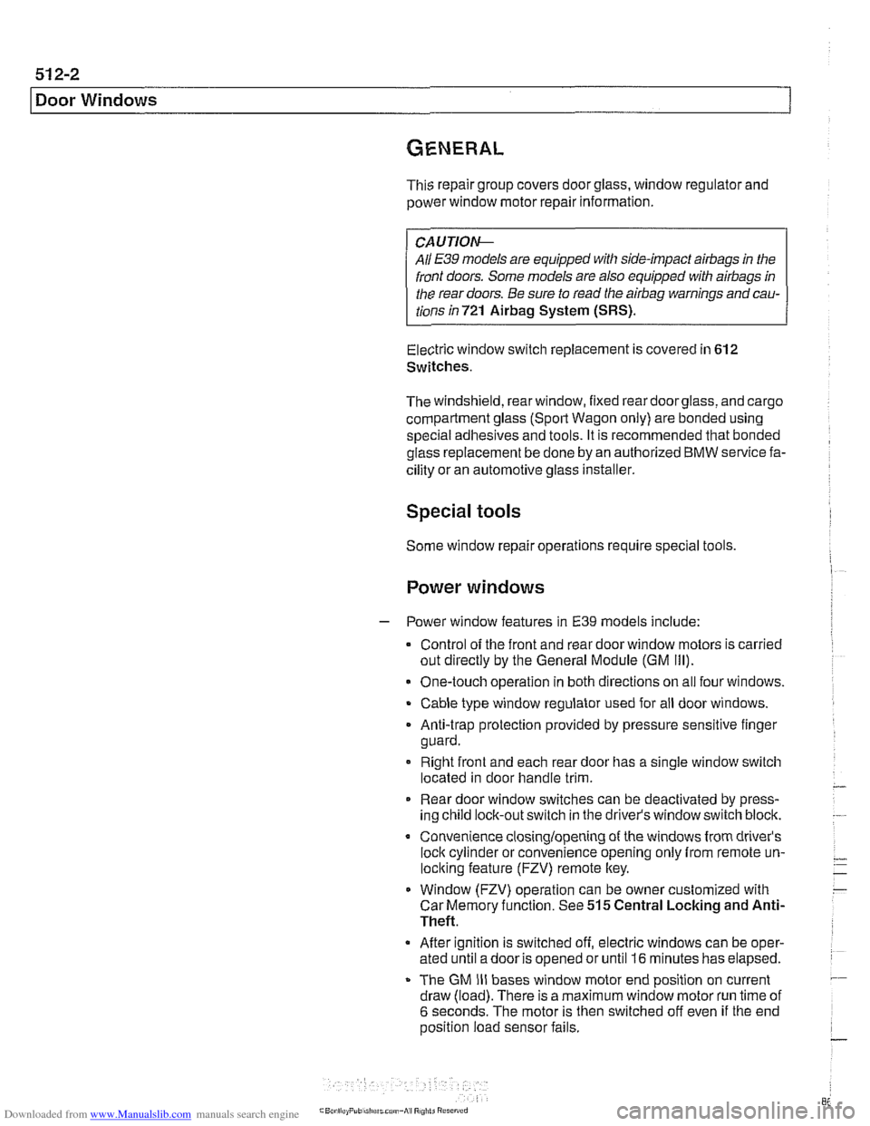
This repair group covers door glass, window regulator and
power window motor repair information.
CA U JIO&
All E39 models are equipped with side-impact airbags in the
front doors. Some models are also equipped with
airbags in
the rear doors. Be sure to read the
airbag warnings and cau-
tions in 721
Airbag System (SRS).
Electric window switch replacement is covered in 612
Switches.
The windshield, rear window, fixed rear doorglass, and cargo
compartment glass (Sport Wagon only) are bonded using
special adhesives and tools. It is recommended that bonded
glass replacement be done by an authorized
BMW service fa-
cility or an automotive glass installer.
Special tools
Some window repair operations require special tools.
Power windows
- Power window features in E39 models include:
Control of the front and rear door window motors is carried
out directly by the General Module (GM
Ill).
One-touch operation in both directions on all four windows.
Cable type window regulator used for all door windows.
. Anti-trap protection provided by pressure sensitive finger
guard.
Right front and each rear door has a single window switch
located in door handle trim.
Rear door window switches can be deactivated by press-
ing child lock-out switch in the driver's window switch block.
Convenience closinglopening of the windows from driver's
loci( cylinder or convenience opening only from remote un-
lociting feature (FZV) remote key.
Window (FZV) operation can be owner customized with
Car Memory function. See 515 Central Locking and Anti-
Theft.
After ignition is switched off, electric windows can be oper-
ated until a door is opened or until
I6 minutes has elapsed.
The GM
IiI bases window motor end position on current
draw (load). There is a maximum window motor run time of
6 seconds. The motor is then switched off even if the end
position load sensor fails.
Page 867 of 1002
Downloaded from www.Manualslib.com manuals search engine
51 2-3
Door Windows
Window switches
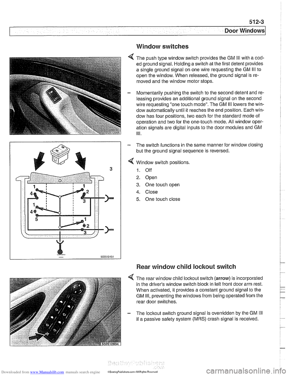
4 The push type window switch provides the GM Ill with a cod-
ed ground signal. Holding a switch at the first detent provides
a single ground signal on one wire requesting the GM
Ill to
open the window. When released, the ground signal is re-
moved and the window motor stops.
- Momentarily pushing the switch to the second detent and re-
leasing provides an additional ground signal on the second
wire requesting "one touch mode". The GM
Ill lowers the win-
dow automatically until it reaches the end position. Each win-
dow has four positions, two each for the standard mode of
operation and two for the one-touch mode. All window oper-
ation signals are digital inputs to the door modules and GM
111.
- The switch functions in the same manner for window closing
but the ground signal sequence is reversed.
4 Window switch positions.
1. Off
2. Open
3. One touch open
4. Close
5. One touch close
Rear window child lockout switch
4 The rear window child lockout switch (arrow) is incorporated
in the driver's window switch block in
leit front door arm rest.
When activated, it provides a constant ground signal to the
GM
Ill, preventing the windows from being operated from the
rear door switches.
- The lockout switch ground signal is overridden by the GM Ill
if a passive safety system (MRS) crash signal is received.