Driveshaft removal BMW 525i 1999 E39 User Guide
[x] Cancel search | Manufacturer: BMW, Model Year: 1999, Model line: 525i, Model: BMW 525i 1999 E39Pages: 1002
Page 617 of 1002
Downloaded from www.Manualslib.com manuals search engine
Driveshaft
- Road test vehicle to check for noise or vibration
CAUTION-
Do not reuse self-locking nuts. These nuts are designed to
be used only once.
Avoid stressing the flex-disc when torquing the bolts.
Do this by counterholding the bolts and turning the nuts
on the flange side.
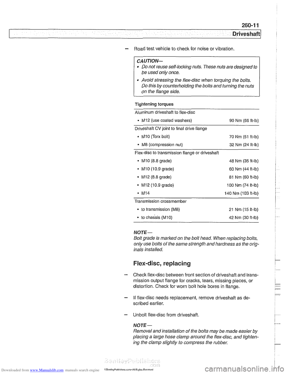
Tightening torques
Alunlinum driveshaft to flex-disc
- MI2 (use coated washers)
90 Nm (66 ft-lb)
Driveshaft
CV joint to final drive flange
Mi0 (Tom bolt)
70 Nm (51 ft-lb)
M8 (compression nut) 32 Nm (24 ft-lb)
Flex-disc to transmission flange or driveshaft
MI0 (8.8 grade) 48 Nm (35 ft-lb)
MI 0 (1 0.9 grade) 60 Nm (44 ft-lb)
- Mi2 (8.8 grade)
81 Nm (60 ft-lb)
- MI2 (10.9 grade) I00 Nm (74 ft-lb)
MI4 140 Nm (103 ft-lb)
Transmission
crossmember
to transmission (ME) 21 Nm (15 ft-lb)
. to chassis (M10) 42 Nm (30 ft-lb)
NOTE-
Boltgrade is marked on the bolt head. When replacing bolts,
only use bolts of the same strength and hardness as the orig-
inals installed.
Flex-disc, replacing
- Checlc flex-disc between front section of driveshafl and trans-
mission output flange for craclts, tears, missing pieces, or
distortion. Check for worn bolt hole bores in flange.
- If flex-disc needs replacement, remove driveshafl as de-
scribed earlier.
- Unbolt flex-disc from driveshaft.
NOTE-
Removal andinstallation of the bolts may be made easier by
placing a large hose clamp around the flex-disc, and tighten-
ing the clamp slightly to compress the rubber.
Page 707 of 1002
Downloaded from www.Manualslib.com manuals search engine
330-1 1
Rear Suspension
Coil spring, removing and installing
Raise car and remove rear wheels.
WARNING-
Make sure the car is firmly supported on jack stands de-
signed for the purpose. Place jack stands underneath struc-
tural chassis points. Do not place jack stands under
suspension parts.
- Remove brake caliper and brake disc. Hang brake caliper
aside with stiff wire. Do not disconnect
bralte fluid hose. See
340 Brakes.
- Remove exhaust system. See 180 Exhaust System.
- Disconnect driveshafl from final drive. See 260 Driveshaft.
- Detach parking bralte cables from mounting bracltets on sub-
frame.
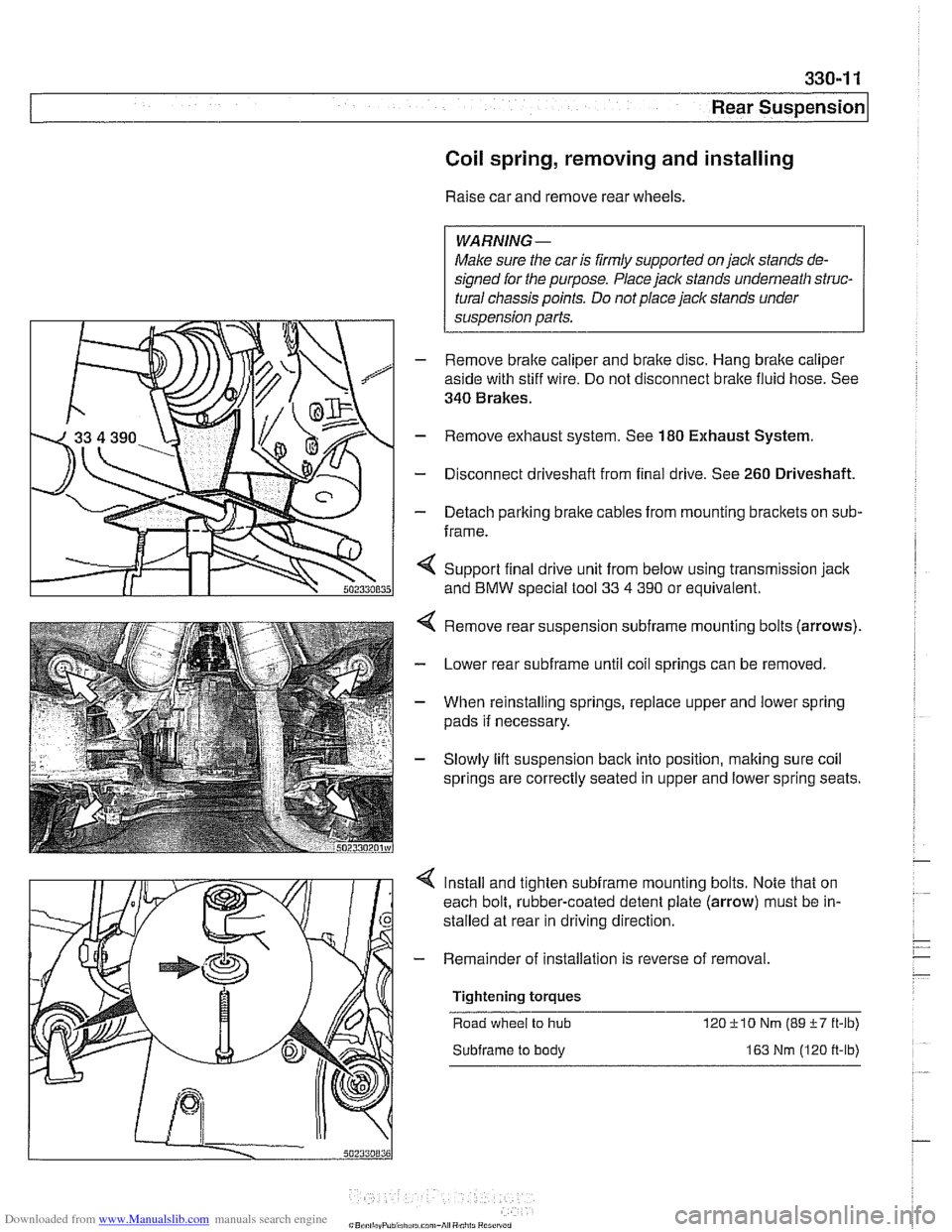
< Support final drive unit from below using transmission jack
and
BMW special tool 33 4 390 or equivalent.
Remove rear suspension
subframe mounting bolts (arrows).
Lower rear
subframe until coil springs can be removed.
When reinstalling springs, replace upper and lower spring
pads if necessary.
Slowly lift suspension
back into position, making sure coil
springs are correctly seated in upper and lower spring seats.
Install and tighten
subframe mounting bolts. Note that on
each bolt, rubber-coated detent plate (arrow) must be in-
stalled at rear in driving direction
- Remainder of installation is reverse of removal
Tightening torques Road wheel
to hub 12OilO Nm (89i-7 ft-lb)
Subframe to body 163 Nm (120 ft-lb)
Page 722 of 1002
Downloaded from www.Manualslib.com manuals search engine
330-26
/ Rear Suspension
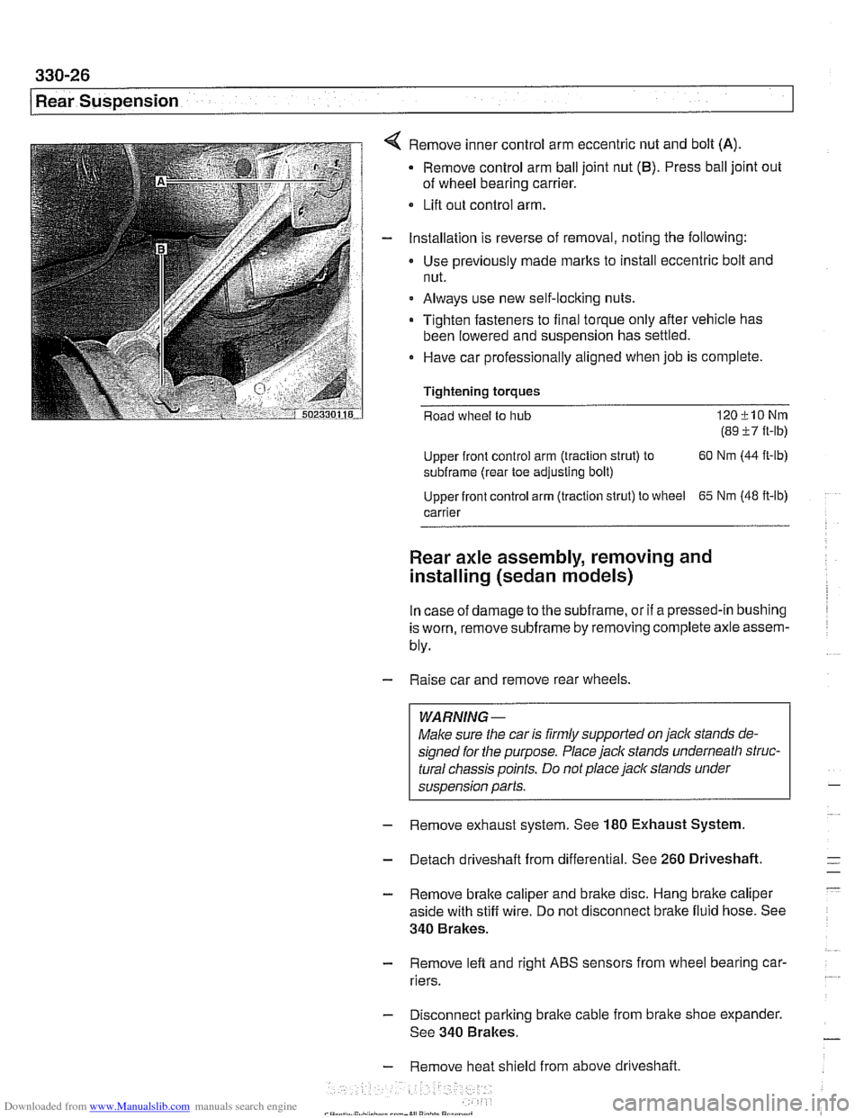
Remove inner control arm eccentric nut and bolt (A)
Remove control arm ball joint nut (6). Press ball joint out
of wheel bearing carrier.
Lifl out control arm.
Installation is reverse of removal, noting the following:
Use previously made
marks to install eccentric bolt and
nut.
Always use new self-locking nuts.
Tighten fasteners to final torque only after vehicle has
been lowered and suspension has settled.
0 Have car professionally aligned when job is complete.
Tightening
torques
Road wheel to hub 120klONm
(89 i7 ft-lb)
Upper front control arm (traction strut) to 60
Nm (44
ft-lb)
subframe (rear toe adjusting bolt)
Upper front control arm (traction strut) to wheel
65 Nm (48 ft-lb)
carrier
Rear axle assembly, removing and
installing (sedan models)
In case of damage to the subframe, or if a pressed-in bushing
is worn, remove
subframe by removing complete axle assem-
bly.
- Raise car and remove rear wheels.
WARNING-
Make sure the car is firmly supported on jack stands de-
signed for the purpose. Place jack stands underneath struc-
tural chassis points. Do not place
jack stands under
suspension parts.
- Remove exhaust system. See 180 Exhaust System
- Detach driveshaft from differential. See 260 Driveshaft.
- Remove brake caliper and brake disc. Hang brake caliper
aside with stiff wire. Do not disconnect brake fluid hose. See
340 Brakes.
- Remove lefl and right ABS sensors from wheel bearing car-
riers.
- Disconnect parking brake cable from brake shoe expander.
See 340 Brakes.
- Remove heat shield from above driveshaft.
Page 724 of 1002
Downloaded from www.Manualslib.com manuals search engine
330-28
Rear Suspension
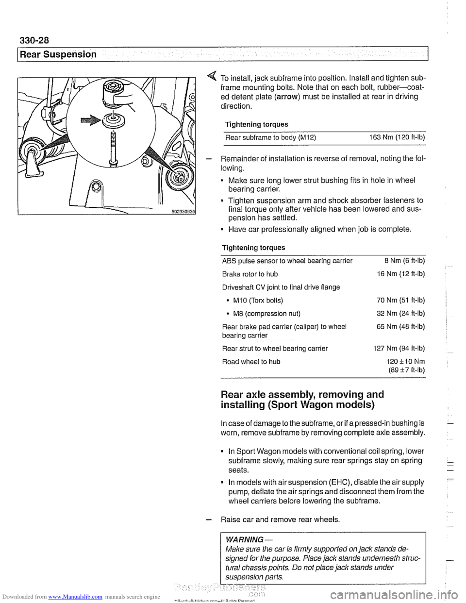
4 To install, jack subframe into position. Install and tighten sub-
frame mounting bolts. Note that on each bolt, rubber-coat-
ed detent plate
(arrow) must be installed at rear in driving
direction.
Tightening torques
Rear
subframe to body (M12) 163 Nm (120 ft-lb)
- Remainder of installation is reverse of removal, noting the fol-
lowing.
Make sure long lower strut bushing fits in hole in wheel
bearing carrier.
111 0 Tighten suspension arm and shoclc absorber fasteners to
502330036 final torque only afler vehicle has been lowered and sus-
pension has settled.
Have car professionally aligned when job is complete
Tightening torques
ABS pulse sensor to wheel bearing carrier 8 Nrn (6 ft-lb)
Brake rotor to hub
16 Nm (12 ft-lb)
Driveshaft
CV joint to final drive flange
- MI0 (Tow bolts) 70 Nm (51 ft-lb)
MB (compression nut) 32
Nm (24 ft-lb)
Rear brake pad
carrler (caliper) to wheel 65 Nm (48 ft-lb)
bear~ng carrler
Rear strut to
wheel bearlng carrler 127 Nm (94 ft-lb)
Road wheel to hub
120210Nrn
(89 57 ft-lb)
Rear axle assembly, removing and
installing (Sport Wagon models)
Incaseof damage to thesubframe, or if apressed-in bushing is
worn, remove
subframe by removing complete axle assembly.
In Sport Wagon models with conventional coil spring, lower
subframe slowly, making sure rear springs stay on spring
seats.
In models with air suspension
(EHC), disable the air supply
pump, deflate the air springs and disconnect them from the
wheel carriers before lowering the subframe.
- Raise car and remove rear wheels.
WARNING-
Page 727 of 1002
Downloaded from www.Manualslib.com manuals search engine
Rear Suspension
- Remainder of installation is reverse of removal, noting the fol-
lowing.
Tighten suspension arm and shock absorber fasteners to
final torque only afler vehicle has been lowered and sus-
pension has settled.
Tightening torques
ABS pulse sensor to wheel bearing carrier 8
Nrn (6 ft-lb)
Air line connection 2 Nrn (18 in-lb)
Brake rotor to hub 16
Nrn (12 ft-lb)
Driveshaft
CV joint to final drive flange
- MI0 (Torx bolts) 70
Nrn (51 ft-lb)
- MB (compression nut) 32 Nrn (24 ft-lb)
Rear
brake pad carrier (caliper) to wheel 65
Nrn (48 ft-lb)
bearing carrier
Road wheel to hub
120ilO Nrn
(89 i-7 ft-lb)
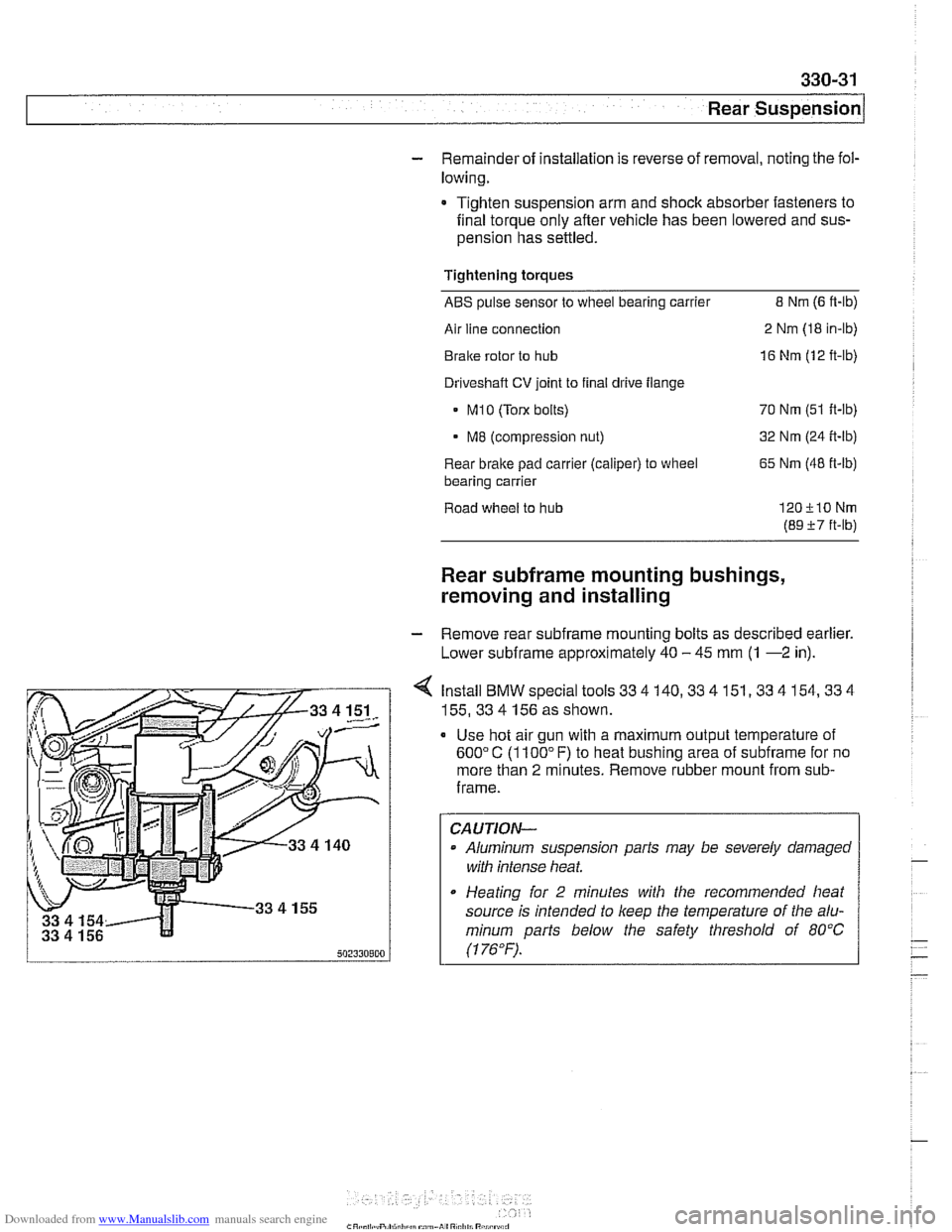
Rear subframe mounting bushings,
removing and installing
- Remove rear subframe mounting bolts as described earlier.
Lower
subframe approximately 40 - 45 mm (1 -2 in).
4 Install BMW special tools 33 4 140,33 4 151,33 4 154,33 4
155,33 4 156 as shown.
Use hot air gun with a maximum output temperature of
600°C (1100" F) to heat bushing area of subframe for no
more than
2 minutes. Remove rubber mount from sub-
frame.
CAUTION-
Aluminum suspension parts may be severely damaged
witli intense heat
* Heating for 2 minutes with the recommended heat
source is intended to
keep the temperature of the alu-
minum
parts below the safety threshold of 80°C
(1 76°F). .
Page 749 of 1002
Downloaded from www.Manualslib.com manuals search engine
Final Drive
Final drive, removing and installing
- Raise rear of car.
WARNING-
Make sure that the car is firmly supported on jack stands de-
signed for the purpose. Place the jaclc stands beneath struc-
tural chassis
~oints. Do not i lace iaclc stands under
( suspension barfs.
Remove exhaust system. See 180 Exhaust System.
Disconnect drive shaft from final drive. See
260 Driveshaft.
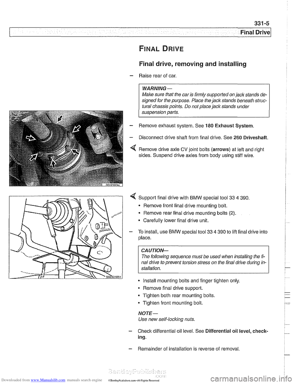
Remove drive axle CV joint bolts (arrows) at left and right
sides. Suspend drive axles from body using stiff wire.
4 Support final drive with BMW special tool 33 4 390.
* Remove front final drive mounting bolt.
Remove rear final drive mounting bolts
(2).
Carefully lower final drive unit.
- To install, use BMW special tool 33 4 390 to lift final drive into
place.
CA UTIOP&
The following sequence must be used when installing the fi-
nal drive to prevent torsion stress on the final drive during in-
Install mounting bolts and finger tighten only.
Remove final drive support.
Tighten both rear mounting bolts.
Tighten front mounting bolt.
NOTE-
Use new self-locking nuts.
- Check differential oil level. See Differential oil level, check-
ing.
- Remainder of installation is reverse of removal.
Page 753 of 1002
Downloaded from www.Manualslib.com manuals search engine
331-9
Final Drive
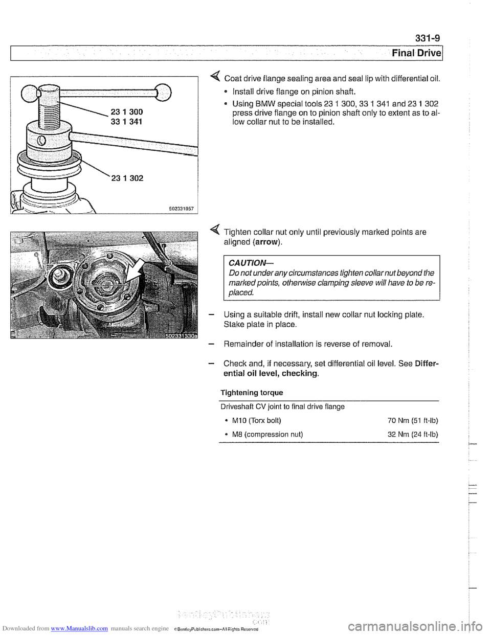
Coat drive flange sealing area and seal lip with differential oil.
* Install drive flange on pinion shaft.
Using
BMW special tools 23 1 300,33 1 341 and 23 1 302
press drive flange on to pinion shaft only to extent as to al-
low collar nut to be installed.
4 Tighten collar nut only until previously marked points are
aligned (arrow).
CAUTION-
Do not underany circumstances tighten collarnut beyond the
markedpoints,
othe~lise clamping sleeve will have to be re-
placed.
- Using a suitable drift, install new collar nut locking plate
Stalte plate in place.
- Remainder of installation is reverse of removal.
- Check and, if necessary, set differential oil level. See Differ-
ential oil level, checking.
Tightening torque Driveshaft
CV joint to final drive flange
MI0 (Torx bolt) 70 Nrn (51 ft-lb)
ME (compression nut) 32 Nrn (24 ft-lb)
Page 994 of 1002
Downloaded from www.Manualslib.com manuals search engine
4 INDEX
Door window anti-trap
512-4 convenience openinglclosing 512.4
regulator and motor 512-1 1
service
512-5 switches 512-3
see also Switches
Double
VANOS see VANOS
Drive
axle
CV joint 331-15 CV joint boot 331-15
rernovinglinstalling 331-14
Drive belt
see Maintenance
Driveabiiity troubleshooting
100-4
Driveaway protection
see EWS (eiectronic immobilization)
Driveshaft aligning
260-7
center bearing, replacing 260-12 CV joint, replacing 260-14
itex-disc, replacing 260-1 1
iront centering guide, replacing 260-13
rernovinglinstailing 260-6
lroubleshooting 260-3
U-joint 260-3
DSC
see Braires
DTC (diagnostic trouble code)
OBD-8
DWA
see Anti-theft alarm
ECM (engine control module)
see 130 under appropriate
iuei
injection system
ECT (engine coolant temperature)
sensor see 130 under appropriate
iuei
injection system
EDK adaptation
130-69
MS 43.0 130-35
EHC see Electronic iieigiit control (EHC)
Electric cooling fan
see Cooling system, cooling
fan
see also Cooiing system, eiectric fan
Electrical switches
see Switches
Electrical system abbreviations
600-14 bus System 600-4
component location table 610-3
components
photos
610-36
Sport Wagon 610-81 engine 121-2
troubleshooting 600-15
voltage and polarily 600-5 wire color codes 600-12
wiring diagrams 600-12
Electrical wiring diagrams
ELE-1
Eiectricaliy heated thermostat
(characteristic map)
170-4
Eiectronic height control (EHC)
300-8, 330-44
Eiectronic immobilization
see EWS (electronic immobilization)
Eiectronics box
(E-box)
610-37
Emergencies
010-18
Emergency brake see
BraBes, parking brake Engine
see also Cylinder head and valvetrain
applications
100-2
compression, testing 113-5
cooling see Cooiing system
crankshaft front oil seai
see Crankshaft oil seals
cyiinder leak-down test 113-8
diagnostic testing 113-1
drive belts
see Maintenance
driveability troubleshooting
100-4
engine management systems 100-2
see also Ignition
see also Fuel injection
fuel supply
130-6
ground connections 100-5
see also 61 0 identilying ieatures 100-3
lubrication svstem
see
~ubricetion system
mount
on-board diagnostics
OBD-I
oxygensensor
see Fuel injection
see also Exhaust system
Dreventive maintenance
see Maintenance
removal/installation
Engine control module (ECM)
see 130 under appropriate iuel
injection system
Engine cooiant temperature (ECT)
sensor see 130 under appropriate iuel
injection
system
Engine cooling fan
see Cooiing system, electric fan
Engine hood
41
0-6 raising to service position 410-6
Engine troubleshooting
see Engine, driveability troubleshooting
EVa~oratiVe control svstem
160-3 see also 130 under aDDroDriate iuel
injection system
Evaporator see
NC
Evaporator temperature sensor see
NC