relay BMW 525i 1999 E39 Owner's Guide
[x] Cancel search | Manufacturer: BMW, Model Year: 1999, Model line: 525i, Model: BMW 525i 1999 E39Pages: 1002
Page 443 of 1002
Downloaded from www.Manualslib.com manuals search engine
Fuel Injection I
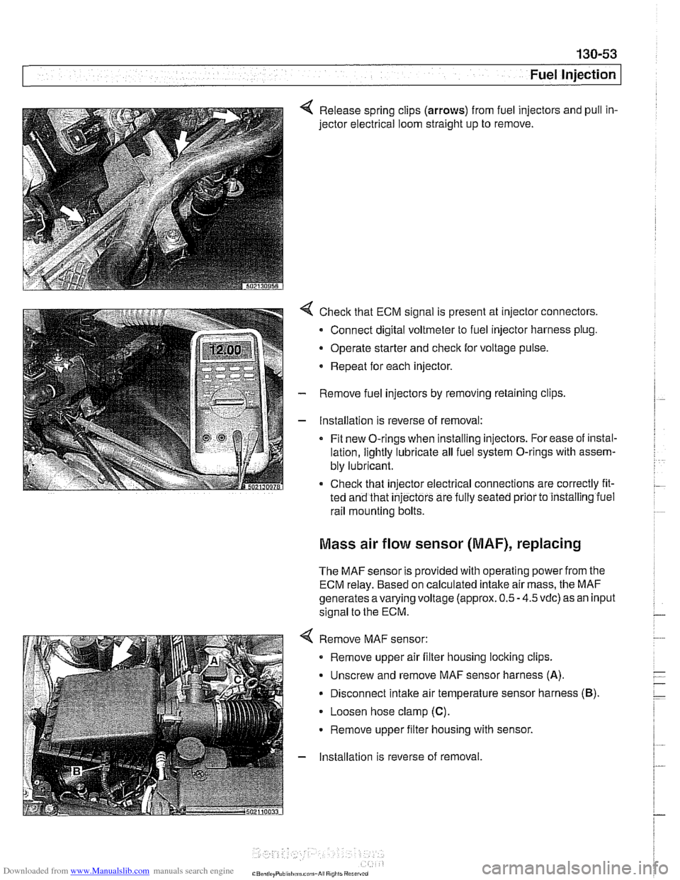
4 Release spring clips (arrows) from fuel injectors and pull in-
jector electrical loom straight up to remove.
4 Check that ECM signal is present at injector connectors.
- Connect digital voltmeter to fuel injector harness plug.
Operate starter and
check for voltage pulse.
* Repeat for each injector.
- Remove fuel injectors by removing retaining clips
- Installation is reverse of removal:
Fit new O-rings when installing injectors. For ease of instal-
lation, lightly lubricate all fuel system O-rings with assem-
bly lubricant.
Check that injector electrical connections are correctly fit-
ted and that
injectors are fully seated prior to installing iuel
rail mounting bolts.
Mass air flow sensor (MAF), replacing
The MAF sensor is provided with operating power from the
ECM relay. Based on calculated intake air mass, the MAF
generates
avarying voltage (approx. 0.5 - 4.5 vdc) as an input
signal to the ECM.
4 Remove MAF sensor:
Remove upper air filter housing locking clips.
Unscrew and remove MAF sensor harness
(A).
Disconnect intake air temperature sensor harness (B).
Loosen hose clamp (C).
Remove upper filter housing with sensor.
- Installation is reverse of removal
Page 444 of 1002
Downloaded from www.Manualslib.com manuals search engine
130-54
I Fuel Injection ldle speed control valve,
testing and replacing
ldle speed is maintained by the ECM through the idle speed
control valve. The idle control function compensates for en-
gine load and engine operating conditions. ldle speed is
adaptive through the ECM and no adjustments can be made.
Before checking valve, confirm that throttle position sensor is
working correctly.
NOTE-
The test given below is an electrical check only. It does not
check the mechanical operation of the valve. If the valve is
sticking, hanging up or is sluggish in operation, substituting a
Inown good valve is the best way to check it.
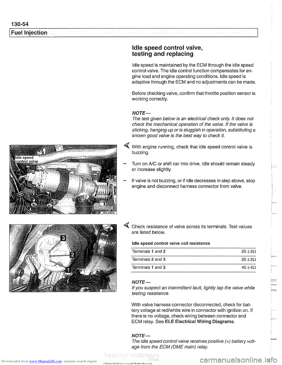
With engine running, check that idle speed control valve is
buzzing.
Turn on
AIC or shift car into drive. ldle should remain steady
or increase slightly.
If valve is not buzzing, or if idle decreases in step above, stop
engine and disconnect harness connector from valve.
4 Check resistance of valve across its terminals. Test values
are listed below.
ldle speed control valve coil resistance
Terminals
1 and 2 20 +2%
Terminals 2 and 3 20 +2Q
Terminals 1 and 3 40 +4%
NOTE-
If you suspect an intermittent fault, lightly tap the valve while
testing resistance.
With valve harness connector disconnected, check for bat-
tery voltage at redlwhite wire in connector with ignition on.
If . ~~ ~~
there is no voltage, check wiring between connector and 7 ECM relay. See ELE Electrical Wiring Diagrams.
NOTE- - The idle speed control valve receivespositive (+) battery volt-
age from the ECM (DME main) relay
Page 449 of 1002
Downloaded from www.Manualslib.com manuals search engine
130-59
Fuel Injection
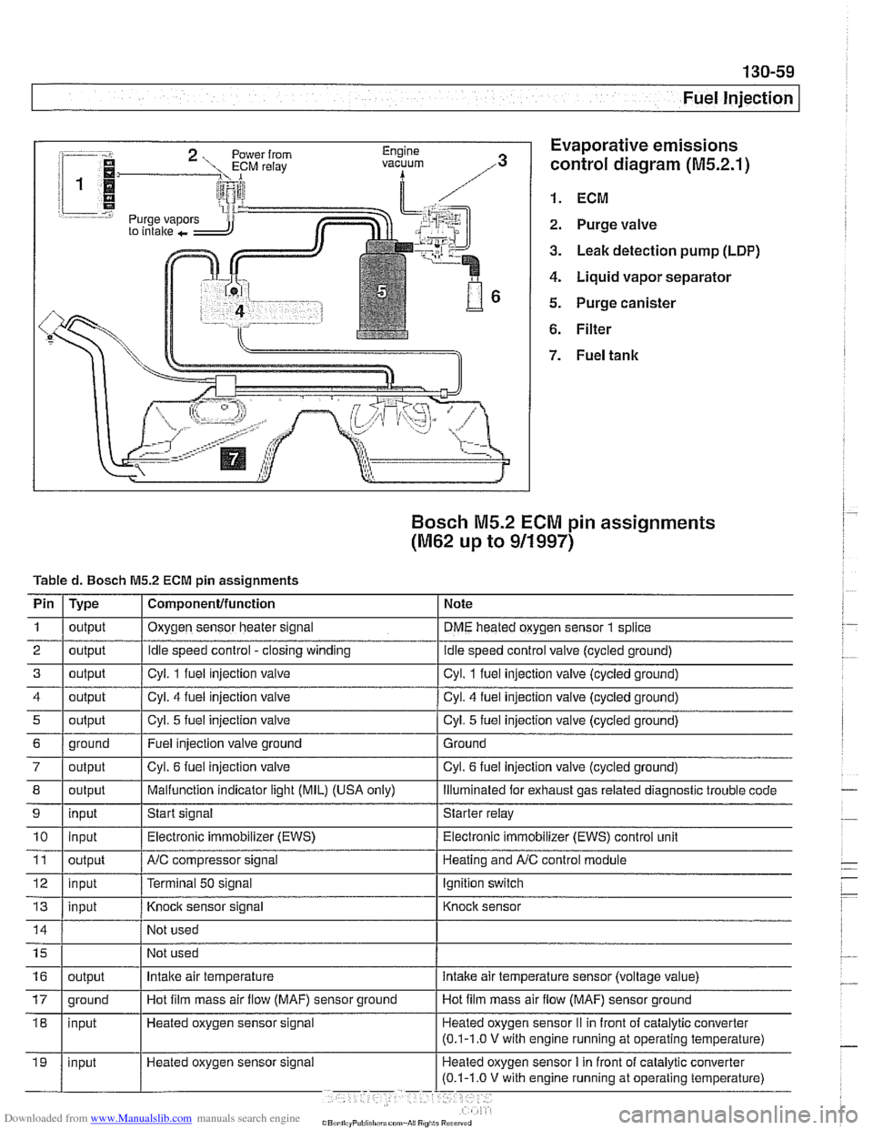
:-- -i. Evaporative emissions
1.
control diagram (M5.2.1)
i 1
i I @ 1. ECM r.=.:-:, 2. Purge valve
3. Leak detection pump (LDP)
4. Liquid vapor separator
5. Purge canister
6. Filter
Bosch M5.2 ECM pin assignments
(M62 up to 911997)
Tabled. Bosch M5.2 ECM pin assignments
I' 1- 1. . . -
4 1 output / Cyl. 4 fuel injection valve I Cyl. 4 fuel injection valve (cycled ground)
Pin
1
2
3
i I
I
7 / output I Cyl. 6 fuel injection valve I Cyl. 6 fuel injection valve (cycled ground)
Type
output
output
output
I I ,
8 1 output I Malfunction indicator light (MIL) (USA only) I lliumlnated for exhaust gas related diagnostic trouble code
5
Component/function
Oxygen sensor heater signal
Idle speed control -closing winding
Cvl. 1 fuel iniection valve Note
DME heated oxygen sensor
1 splice
idle speed control valve (cycled ground)
Cvl. 1 fuel iniection valve lcvcled around)
6 1 ground I Fuel injection valve ground 1 Ground
output
9
Not
used
Not used
11
12
13
Cyl. 5 fuel injection valve
10 1 input I Electronic immobilizer (EWS) / Electronic immobilizer (EWS) control unit
input
Heated oxygen sensor signal Cyl.
5 fuel injection
valve (cycled ground)
output
input
input
16
Start signal Starter relay
NC compressor signal
Terminal
50 signal
Knock sensor signal
17 1 ground I Hot film mass air flow (MAF) sensor ground I Hot film mass air flow (MAF) sensor ground
output Heating and
A/C control module
Ignition switch
Knock sensor
Intake air temperature intake air temperature sensor (voltage value)
Page 450 of 1002
Downloaded from www.Manualslib.com manuals search engine
130-60
/Fuel lniection
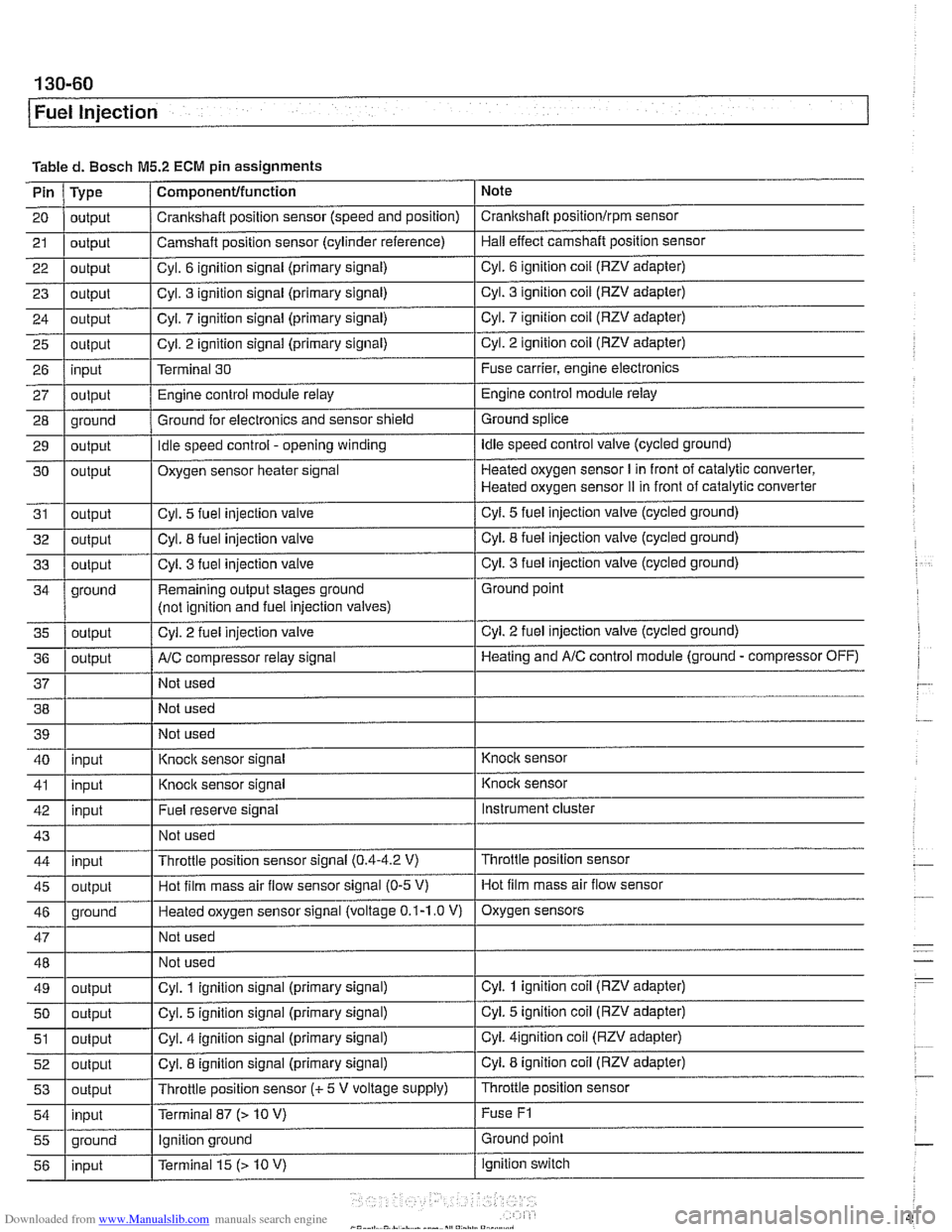
Tabled. Bosch M5.2 ECM pin assignments
Note
Pin
21
20 I output / Crankshaft position sensor (speed and position) I Crankshaft positionlrpm sensor
23
I - I I 29 1 output I Idle speed control - opening winding I Idle speed control valve (cycled ground)
Type
22
1 output I Cvl. 6 ignition signal (primary signal) I Cyl. 6 ignition coil (RZV adapter)
output
25
26
27
28
Component/function
24 1 outout I Cvl. 7 iqnition siqnal (primary signal) I Cyl. 7 ignition coil (RZV adapter)
output
4 outbut I' I - I Cyl. 3
fuel injection valve I Cyl. 3 fuel injection valve (cycled ground)
Camshaft position
sensor (cylinder reference)
output input
output
oround
30
31
32
ground Hall effect camshaft position sensor
Cyl. 3 ignition signal (primary signal)
output
I
Cyl. 3 ignition coil (RZV adapter)
. - . .. . .
Cyl. 2 ignition signal (primary signal)
Terminal 30
Engine control module relay
Ground for electronics and sensor shield
output
output
outout
Remaining output stages ground
(not iclnition and fuel iniection valves) Cyl.
2 ignition coil (RZV adapter)
Fuse carrier, engine electronics
Engine control module relay
Ground splice ,
Cyl. 2 fuel injection valve
Oxygen sensor heater signal
Cyl. 5
fuel injection valve
Cvl. 8 fuel iniection valve
AIC comuressor relav sianal
Heated oxygen sensor I in front of catalytic converter,
Heated oxygen sensor
iI in front of catalytic converter
Cyl.
5 fuel injection valve (cycled ground)
Cvl. 8 fuel iniection valve (cycled ground)
. -
Not used Ground point
Cyl.
2 fuel injection valve (cycled ground)
Heatinq and AIC control module (ground - compressor OFF)
38 Not used
40 39
1 I Not used
I'
I . I
I' I -. I
46 1 ground I Heated oxygen sensor signal (voltage 0.1-1.0 V) I Oxygen sensors
41
1 inuut I Knock
sensor signal I Knock sensor
input
I
I I
Instrument cluster
I' I I 55 1 ground I Ignition ground I Ground point
Knock sensor signal
43
1 I Not used I
Fuel reserve signal
42
Throttle position sensor
47
48
49
50
51
52
53
54
Knoclc sensor
input
45
1 outout I Hot film mass air flow sensor signal (0-5 V) I Hot film mass air flow sensor
Throttle position sensor signal
(0.4-4.2 V) 44
input
output
output
output
output
output
inout
I - I
Not used
Not used
Cyl. 1 ignition signal (primary signal)
Cyl. 5 ignition signal (primary signal)
Cyl. 4 ignition signal (primary signal)
Cyl. 8 ignition signal (primary signal)
Throttle position sensor
(c 5 V voltage supply)
Terminal 87
f> 10 V)
ignition switch
56
Cyl. 1 ignition coil (RZV adapter)
Cyi. 5 ignition coil (RZV adapter)
Cyi.
4ignition coil (RZV adapter)
Cyl. 8 ignition coil (RZV adapter)
Throttle position sensor
Fuse
F1
input Terminal 15 (> 10 V)
Page 451 of 1002
Downloaded from www.Manualslib.com manuals search engine
-. -
Fuel Injection
I 68 1 / Not used
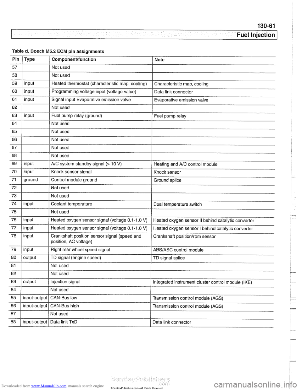
Table
d. Bosch
M5.2 ECM pin assignments
I I I
69 1 input I AIC system standby signal (> 10 V) 1 Heating and AIC control module
Pin
57
58
59
60
61
62
63
64
65 66
67
Type
input
input
input
input
I 70
72
73
74
Componentlfunction
Not used
Not used
Heated thermostat (characteristic map, cooling)
Programming voltage input (voltage
value)
Signal input Evaporative emission valve
Not used
Fuel pump relay (ground)
Not used
Not used
Not used
Not used
75
76
77
78
79
80
Note
Characteristic map, cooling
Data
llnlc connector
Evaporative emission valve
Fuel pump relay
71 1 ground I Control module ground I Ground splice
input
input
81
input input
input
input
output Not used
I
Knock sensor signal
Not used
Not used
Coolant temperature
82 1 I Not used
83
I I
Knock sensor
Dual temperature
swltch
Not used
Heated oxygen sensor signal (voltage
0.1-1.0 V)
Heated oxygen sensor
signal (voltage 0.1-1.0 V)
Crankshaft position sensor signal (speed and
position, AC voltage)
Right rear wheel speed signal
TD signal (engine speed)
85
I I I
Heated oxygen sensor II behind catalytic converter
Heated oxygen sensor
I behind catalytic converter
Cranitshaft positionlrpm sensor
ABSIASC control module
TD signal splice
84 1 / Not used 1
output
88
86
1 input-output 1 CAN-Bus high I Transmission conlrol module (AGS)
input-output
Injection signal
input-output Integrated instrument cluster control
module (IKE)
CAN-Bus low Transmission control module (AGS)
Data
linlc TxD Data link connector
Page 452 of 1002
Downloaded from www.Manualslib.com manuals search engine
130-62
Fuel Injection
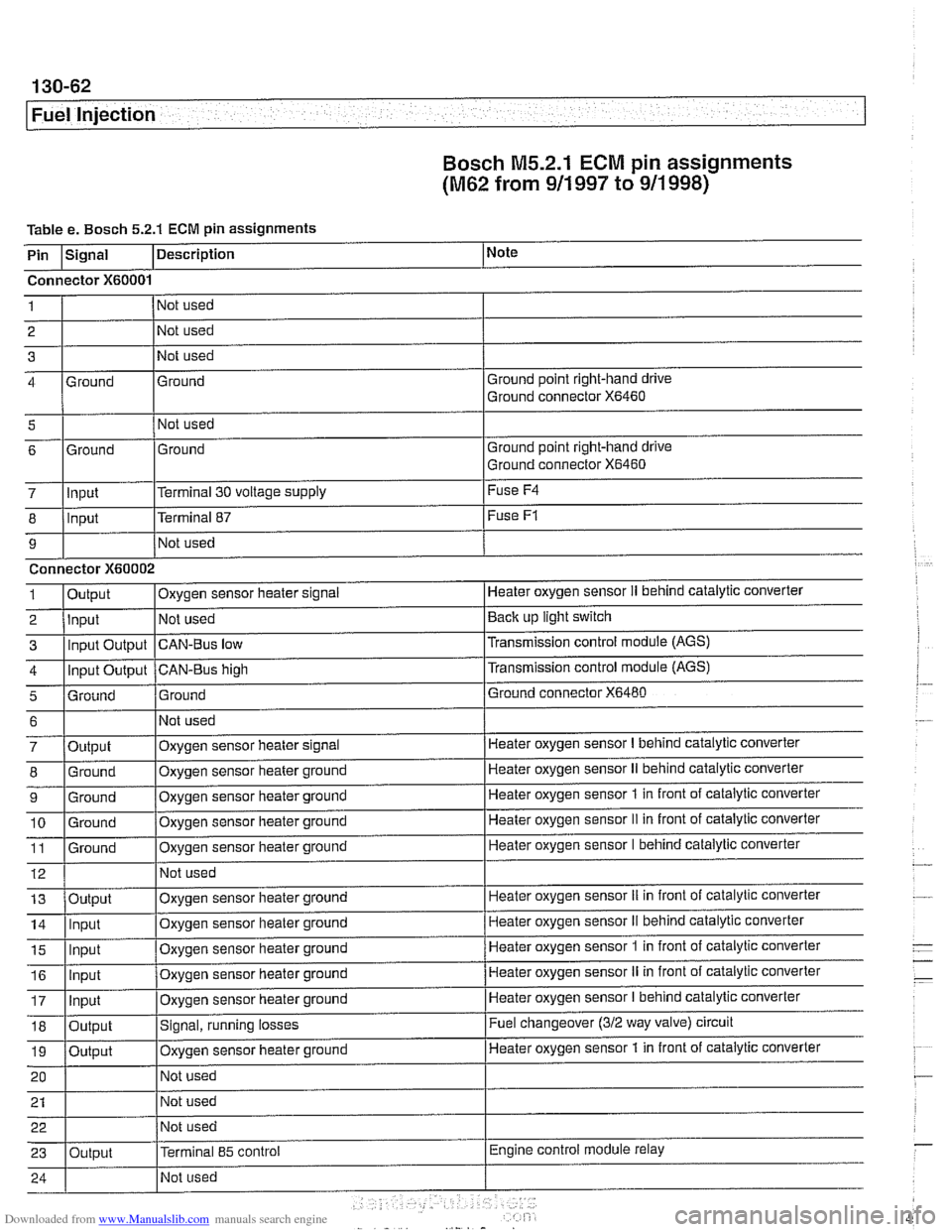
Bosch M5.2.1
ECM pin assignments
(M62 from 911 997 to 911 998)
Table e. Bosch 5.2.1 ECM pin assignments
i I I
5 1 I Not used
I
I I
Note
I I I
7 lln~ut l~erminal 30 voltage supply I Fuse
F4
Description
Pin
Ground point right-hand drive
Ground connector
X6460
I I I
Signal
Connector
X60001
Ground 4 1
2
3 Ground
Ground point right-hand drive
Ground connector
X6460 6
8
9 1
2
3
4
5
Not used
Not used
Not used
-
6
7
8
9
10 11
12
Ground
Input
Connector
X60002
Output Input Input Output
Input Output
Grniind
. -
13
14
15
Ground
- .- -
Output
Ground
Ground
Ground
Ground
16
17
18
19
20
21 22
23
.
Terminal 87
Not used
Oxygen sensor heater
slgnal
Not used
CAN-Bus low
CAN-BUS high
Ground
Output Input
ln~ut
Fuse F1
Heater oxygen sensor II behind cataiytic converter
Back up light switch
Transmission control module (AGS)
Transmission control module
(AGS)
Ground connector X6480
Not used
Oxygen sensor heater signal
Oxygen sensor heater ground
Oxygen sensor heater ground
Oxygen sensor heater ground
Oxygen sensor heater ground
Not used
Input
Input
Output
Output
Output Heater oxygen sensor
I behind catalytic converter
Heater oxygen sensor
II behind catalytic converter
Heater oxygen sensor
1 in front of catalytic converter
Heater oxygen sensor
II in front of catalytic converter
Heater oxygen sensor I behind catalytic converter
Oxygen sensor heater ground
Oxygen sensor heater ground
Oxvqen sensor heater ground Heater oxygen sensor
iI in front
of catalytic converter
Heater oxygen sensor
II behind catalytic converter
Heater oxygen sensor
1 in front of catalytic converter . -
Oxygen sensor heater ground
Oxygen sensor heater ground
Signal, running losses
Oxygen sensor iieater ground
Not used
Not used
Not used
Terminal
85 control
Heater oxygen sensor II in front of catalytic converter
Heater oxygen sensor
I behind catalytic converter
Fuel changeover
(312 way valve) circuit
Heater oxygen sensor 1 in front of catalytic converter
Engine control module relay
Page 454 of 1002
Downloaded from www.Manualslib.com manuals search engine
-
Fuel Injection
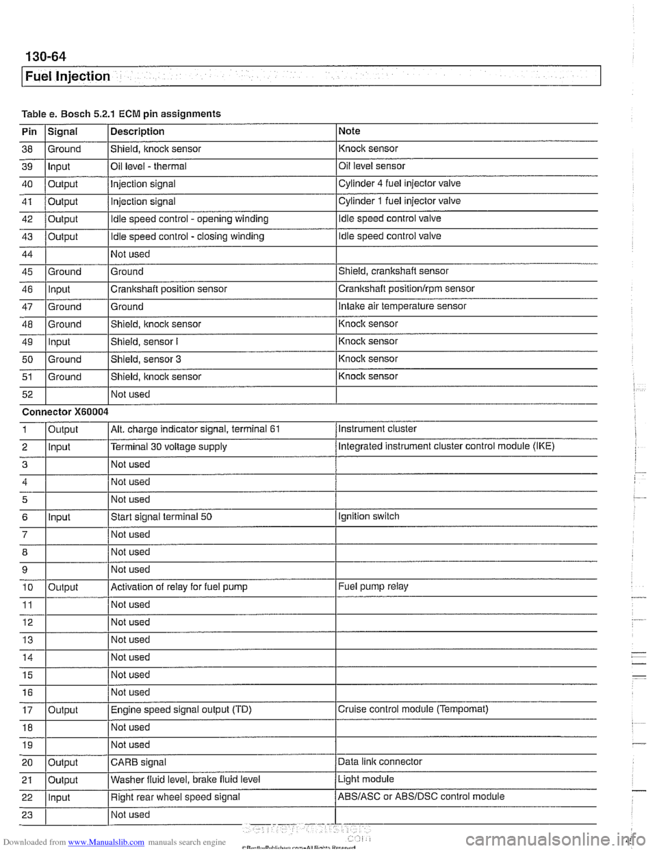
Table e. Bosch 5.2.1 ECM pin assignments
Pin
I~iqnal 1 Description 1 Note
I I I
46 llnput ICrankshaft position sensor Icrankshaft positionlrpm sensor
38
39
40
41
42
43
44
45 Ground Input
Output
Output
Output
Output
Ground
47
48
49
50
51
Not used
I Not used
52
Shield, knock sensor
Oil level
- thermal
Injection signal
injection signal
Idle speed control - opening winding
Idle speed control - closing winding
Not used
Ground
Ground
-- Ground Input
Ground
Ground Not used Knock sensor
Oil level sensor
Cylinder
4 fuel injector
valve
Cylinder
1 fuel injector valve
Idle speed control valve
Idle speed control valve
Shield, crankshaft sensor
5
6
7
12 Not used
Ground
Intake air temperature sensor
Connector
X60004
8
9 10
11
14 1 1 Not used I
Shield, knock sensor
Shield, sensor
I
Shield, sensor 3
Shield, itnock sensor
Input
- Knoclc sensor
Knock sensor
Knock sensor
Knock sensor
Instrument cluster
Output
2 llnput l~erminal 30 voltage supply /Megrated instrument cluster control module (IKE)
Alt. charge indicator signal, terminal 61 1
Not used
Start signal terminal
50
Not used
15
16
17
18
Output
Ignition switch
Not used
Not used
Activation of relay for fuel pump
Not used
19
Fuel pump relay
Output Not used
I I I 20 loutput ICARB signal /Data link connector
Not
used
Not used
Engine speed signal output (TD)
Not used
Light module
21
Cruise control module (Tempomat)
22 llnput I Right rear wheel speed signal /ABS/ASC or ABSIDSC control module
Oulput
Washer
fluid level,
brake fluid level
Page 455 of 1002
Downloaded from www.Manualslib.com manuals search engine
Fuel Injection
Table Pin
24
25
26
27
28
29
30
31
32
33
34
35
36
37
38
39
40
1
2
3
4
5
6
7
8
9
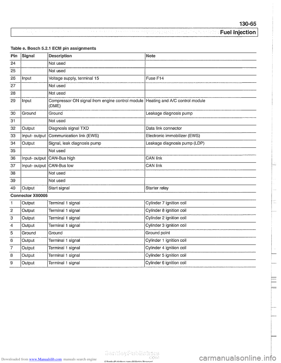
e. Bosch 5.2.1
Signal
Input
Input
Ground
Output Input- output
Output
Input- output
Input- output
Output
Connector
X60005
Output
Output
Output
Output
Ground
Output
Output
Output
Output
ECM pin assignments
Description
Not used
Not used
Voltage supply, terminal
15
Not used
Not used
Compressor ON signal from engine control module
(DME)
Ground
Not used
Diagnosis signal TXD
Communication
link (EWS)
Signal, leak diagnosis pump
Not used
CAN-Bus high
CAN-Bus low Not used
Not used
Start
signal
Terminal 1 signal
Terminal
1 signal
Terminal
1 signal
Terminal
1 signal
Ground
Terminal
1 signal
Terminal
1 signal
Terminal
1 signal
Terminal 1 signal Note
Fuse
F14
Heating
and AIC control module
Lealtage diagnosis pump
Data
iinit connector
Electronic immobilizer (EWS)
Leakage diagnosis pump (LDP)
CAN link
CAN link
Starter relay
Cylinder
7 ignition coil
Cylinder 8 ignition coil
Cylinder
2 ignition coil
Cylinder
3 ignition coil
Ground point
Cylinder
1 ignition coil
Cylinder
4 ignition coil
Cylinder 5 ignition coil
Cylinder
6 ignition coil
Page 456 of 1002
Downloaded from www.Manualslib.com manuals search engine
Fuel Injection
When system faults are detected, a diagnostic trouble code
(DTC) is stored in the engine control module (ECM). The MIL
also illuminates
if an emissions-related fault is detected.
When faults arise, or
if the malfunction indicator lamp (MIL) is
illuminated, begin troubleshooting by connecting BMW ser-
vice tester
DISplus, MoDiC, GTl or equivalent scan tool. The
capabilities of OBD
II software has the potential to save hours
of diagnostic time and to help avoid incorrect component re-
placement and possible damage to system components.
CA UTIOI\C
The tests in this section may set fault codes (DTCs) in the
ECM and illuminate the MIL. After all testing is completed,
access and clear DTC fault memory using an OBD
I1 or
BMW compatible scan tool. See OBD On-Board Diag-
nostics.
. Only use a digital multimeter for electrical tests.
Relay positions can vary. Be sure to confirm relay posi-
tion by identifying the wiring in the
socket using the wir-
ing diagrams found in ELE Electrical Wiring
Diaqrams.
NOTE-
= OBD I1 fault memory (including an illuminated MIL) can
only be reset using the special scan tool. Removing the
connector from the ECM or disconnecting the battery will
not erase the fault memory.
0 The BMW-dedicated 20-pin diagnostic link connector
(DLC) is in the right rear of the engine compartment. The
20-pin DLC was eliminated on models after
6/2000.
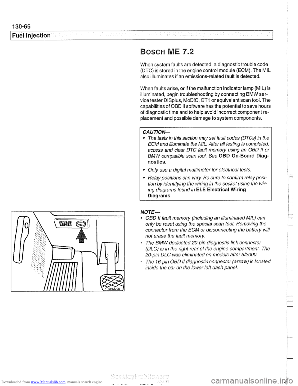
The 16-pin OBD I1 diagnostic connector (arrow) is located
inside the car on the lower left dash panel.
Page 459 of 1002
Downloaded from www.Manualslib.com manuals search engine
--
Fuel Injection I
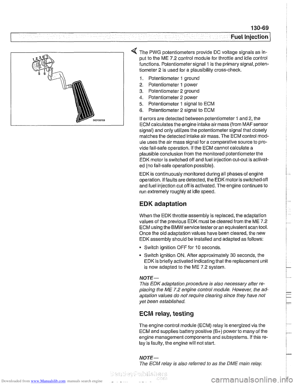
The PWG potentiometers provide DC voltage signals as in-
put to the ME 7.2 control module for throttle and idle control
functions. Potentiometer signal
1 is the primary signal, poten-
tiometer 2 is used for a plausibility cross-check.
1. Potentiometer 1 ground
2. Potentiometer
1 power
3. Potentiometer 2 ground
4. Potentiometer 2 power
5. Potentiometer 1 signal to ECM
6. Potentiometer 2 signal to ECM
If errors are detected between potentiometer
1 and 2, the
ECM calculates the engine intake air mass (from
MAFsensor
signal) and only utilizes the potentiometer signal that closely
matches the detected
intake air mass. The ECM control mod-
ule uses the air mass signal for a comparative source to pro-
vide fail-safe operation.
If the ECM cannot calculate a
plausible conclusion from the monitored potentiometerthe
EDK motor is switched off and fuel injection cut-out is activat-
ed (no fail-safe operation possible).
EDK is continuously monitored during all phases of engine
operation. If faults are detected, the EDK motor is switched off
and fuel injection cut off is activated. The engine continues to
run extremely roughly at idle speed.
EDK adaptation
When the EDK throttle assembly is replaced, the adaptation
values of the previous EDK must be cleared from the ME 7.2
ECM using the BMW service testeroran equivalentscan tool.
Once the old adaptation values have been cleared, the new
EDK assembly should be installed and adapted as follows:
0 Switch ignition OFF for 10 seconds.
* Switch ignition ON. Afler approximately 30 seconds, the
EDK is briefly activated indicating that the replacement unit
is now adapted to the ME 7.2 system.
NOTE-
This EDK adaptation procedure is also necessary after re-
placing the
ME 7.2 engine control module. However, the ad-
aptation values do not require clearing since they have not
yet been established.
ECM relay, testing
The engine control module (ECM) relay is energized via the
ECM and supplies battery positive
(B+) power to many of the
engine management components and subsystems. If this re-
lay is faulty, the engine will not start.
NOTE-
The ECM relay is also referred to as the DME main relay