relay BMW 525i 1999 E39 Repair Manual
[x] Cancel search | Manufacturer: BMW, Model Year: 1999, Model line: 525i, Model: BMW 525i 1999 E39Pages: 1002
Page 917 of 1002
Downloaded from www.Manualslib.com manuals search engine
Central Lockina and ~nti- heft
EWS control module, replacing
NOTE-
EWS control module location varies depending on version of
EWS installed.
Checlc the table €39 EWS applications.
- Disconnect battery negative (-) cable.
CA UTIOI\C
Prior to disconnecting the battery, read the battery discon-
nection cautions given in
001 General Warnings and Cau-
tions.
- EWS II: Control module is accessible from behind glove com-
partment.
Remove trim below glove compartment.
Lower relay and module holder to access EWS control
module
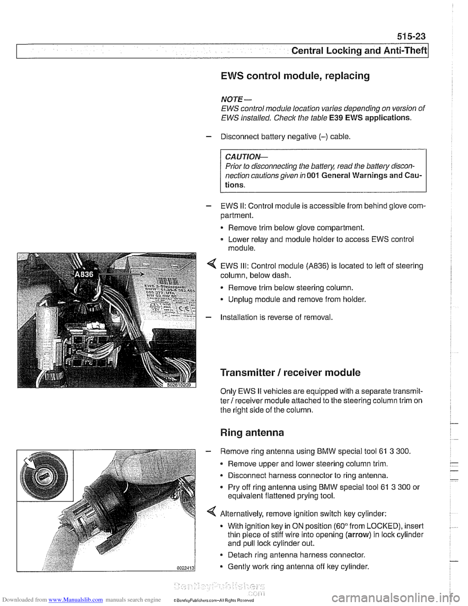
EWS
Ill: Control module (A836) is located to left of steering
column, below dash.
Remove trim below steering column.
Unplug module and remove from holder.
Installation is reverse of removal.
Transmitter / receiver module
Only EWS II vehicles are equipped with a separate transmit-
ter! receiver module attached to the steering column trim on
the right side of the column.
Ring antenna
- Remove ring antenna using BMW special tool 61 3 300.
Remove upper and lower steering column trim.
Disconnect harness connector to ring antenna.
Pry off ring antenna using
BMW special tool 61 3 300 or
equivalent flattened prying tool.
Alternatively, remove ignition switch key cylinder: With ignition
ltey in ON position (60" from LOCKED), insert
thin piece of stiff wire into opening (arrow) in lock cylinder
and pull lock cylinder out.
- Detach ring antenna harness connector.
Gently
work ring antenna off ltey cylinder.
CaonliayPuliiliirrl can,-A, R0,il. Rurilrrrri
Page 965 of 1002
Downloaded from www.Manualslib.com manuals search engine
On-Board Diagnostics
Catalyst monitoring. Thisstrategy monitors the outputofthe
precatalyst and post-catalyst oxygen sensors, comparing the
oxygen content going into the catalytic converter to the
oxygen leaving the converter.
The diagnostic executive
lknows that most of the oxygen
should be used up during the oxidation phase. If it detects
higherthan programmed values, afault is set and the MIL
illuminates.
Misfire detection. This strategy monitors crankshaft speed
fluctuations and determines if an enoine misfire occurs bv
monitoring variations in speed between each crankshaft
sensortrigger point. This strategy is so finely tuned that it can
determine the severity of the misfire.
The system determines
if a misfire is occurring, as well as
other pertinent misfire
information such as:
Specific
cylinder(s)
Severity of the misfire event
Emissions relevant or catalyst damaging
Misfire detection is an on-going monitoring process that is
only disabled under certain limited conditions.
Secondary air injection monitoring. Secondary air
injection is used to reduce HC and CO emissions during
engine warm up. Immediately following a cold engine start
(-1 0" to 40°C), fresh air (and therefore oxygen) is pumped
directly into the exhaust
manifold. By injecting additional
oxygen into the exhaust manifold, catalyst warm-up time is
reduced.
Secondary air system components are:
Electric air injection pump
* Electric pump relay
* Non-return valve
Vacuum
I vent valve
- Stainless steel air injection pipes
Vacuum reservoir
The secondary air system is monitored via the use
of the pre-
catalyst oxygen sensors. Once the air pump is active and air
is injected into the system, the signal at the oxygen sensor
reflects a lean condition. If the oxygen sensor signal does not
change, a fault is set and the faulty
bank(s) identified. If after
completing the next cold startafault is again present, the MIL
illuminates.
Page 982 of 1002
Downloaded from www.Manualslib.com manuals search engine
OBD-22
I On-Board Diagnostics
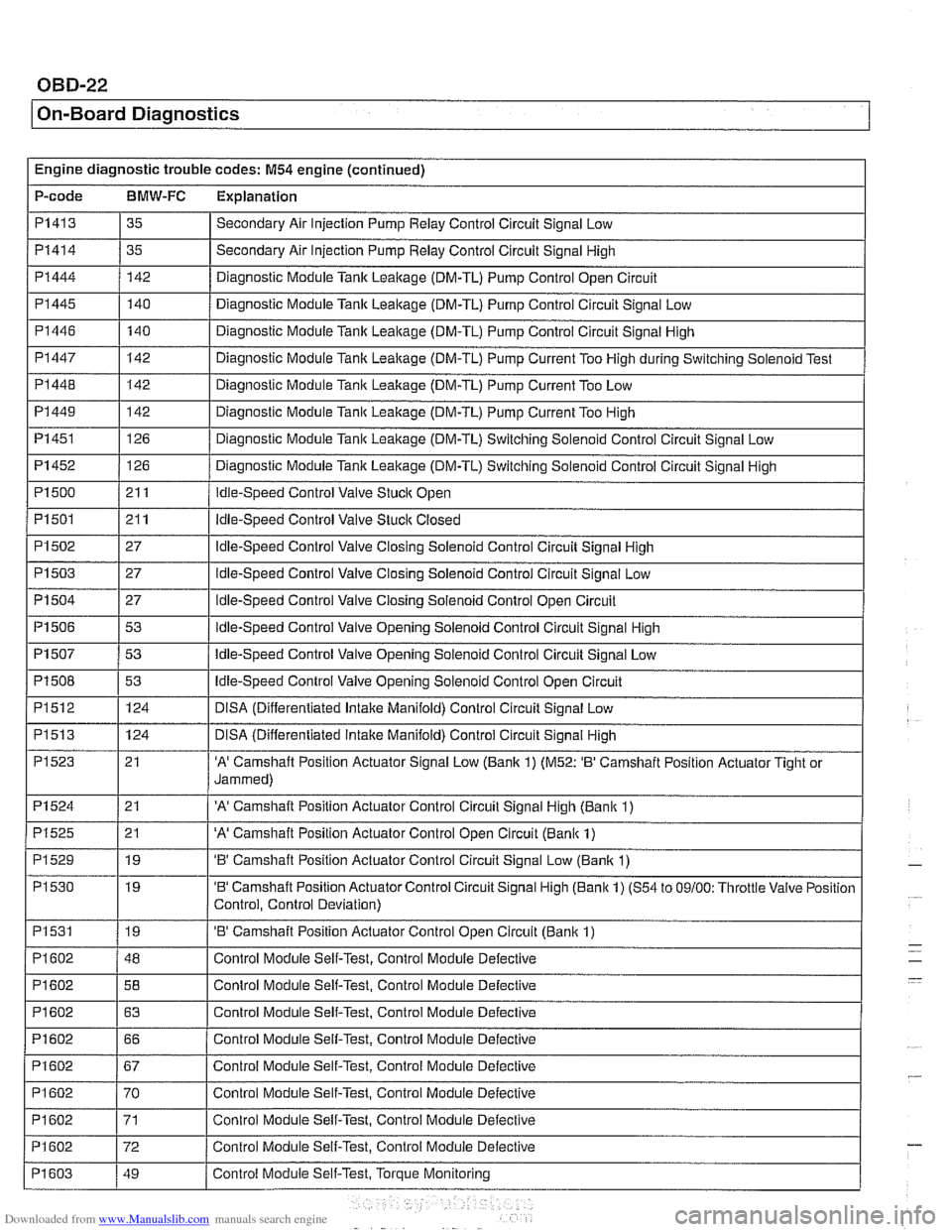
Engine diagnostic trouble codes: M54 engine (continued)
P-code
BMW-FC Explanation
PI 41 3
PI414
PI444
PI 445
PI446
PI447
PI 448
PI 449
PI 451
35
35
142 140
140
142
142
142
126
Secondary Air Injection Pump Relay Control Circuit Signal Low
Secondary Air Injection Pump
Relay Control Circuit Signal High
Diagnostic Module Tank Leakage (DM-TL) Pump Control Open Circuit
Diagnostic Module Tank
Leaitage (DM-TL) Pump Control Circuit Signal Low
Diagnostic Module Tank Lealtage (DM-TL) Pump Control Circuit Signal High
Diagnostic Module
Tanlc Leakage (DM-TL) Pump Current Too High during Switching Solenoid Test
Diagnostic Module
Tank Leakage (DM-TL) Pump Current Too Low
Diagnostic Module
Tank Leakage (DM-TL) Pump Current Too High
Diagnostic Module
Tank Leaitage (DM-TL) Switching Solenoid Control Circuit Signal Low
Page 989 of 1002
Downloaded from www.Manualslib.com manuals search engine
On-Board ~ia~nosticsl
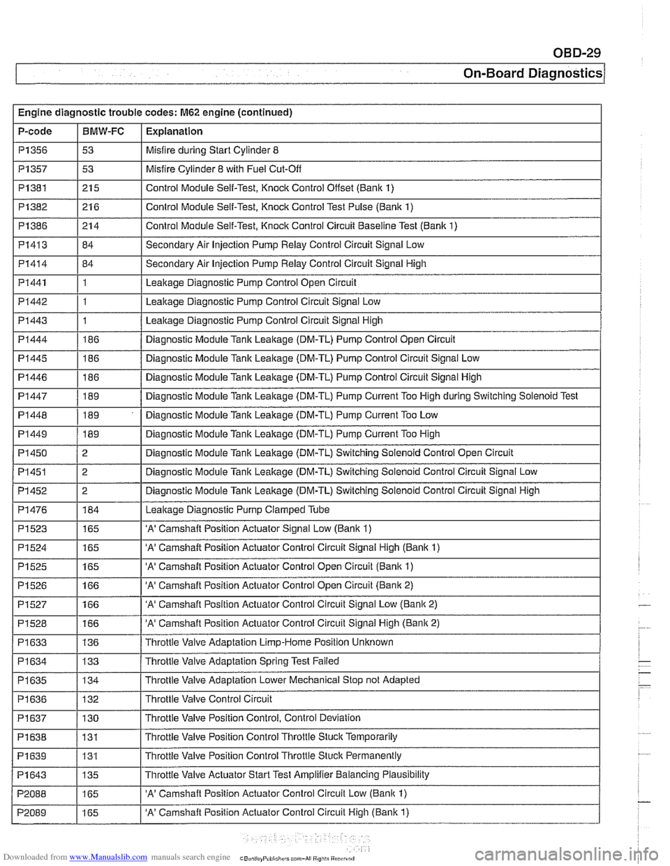
Engine diagnostic trouble codes: M62 engine (continued)
P-code
I I -
I I - -.
PI445 1186 / Diagnostic Module Tank Leakage (DM-TL) Pump Control Circuit Signal Low
PI357
PI382
PI386
PI413
PI414
PI441
PI442
PI443
PI444
P1356 1 53 I Misfire during Start Cylinder 8
BMW-FC
I P1523
I
I - -
1165 I 'A' Camshaft Position Actuator Signal Low (Banlc 1)
Explanation
P1381 1215 I Control Module Self-Test, Knock Control Onset (Bank 1)
53
21 6
21 4
84
84
1
1
1
186
PI 446
PI 447
PI 448
PI449
PI 450
PI451
PI452
PI476
Misfire Cylinder 8 with Fuel Cut-Off
Control Module Self-Test, Knock Control Test Pulse (Bank 1)
Control Module Self-Test, Knock Control Circuit Baseline Test (Bank 1)
Secondary Air Injection Pump Relay Control Circuit Signal Low
Secondary Air Injection Pump
Relay Control Circuit Signal High
Leakage Diagnostic Pump Control Open Circuit
Leakage Diagnostic Pump Control Circuit Signal Low
Leakage Diagnostic Pump Control Circuit Signal High
Diagnostic Module Tank Leakage (DM-TL) Pump Control Open Circuit
186
189
189
189
2
2
2
184
P1524
P1525
P1526
PI527
PI528
PI633
PI 634
PI 635
I I
PI 638 / 131 I Throttle Valve Position Control Throttle Stuck Temporarily
. -
Diagnostic Module Tank Leakage (DM-TL) Pump Control Circuit Signal High
Diagnostic Module
Tank Leakage (DM-TL) Pump Current Too High during Switching Solenoid Test
Diagnostic Module Tank Leakage (DM-TL) Pump Current Too Low
Diagnostic Module
Tank Leakage (DM-TL) Pump Current Too High
Diagnostic Module Tank Leakage (DM-TL) Switching Solenoid Control Open Circuit
Diagnostic Module
Tank Leakage (DM-TL) Switching Solenoid Control Circuit Signal Low
Diagnostic Module
Tank Leakage (DM-TL) Switching Solenoid Control Circuit Signal High
Leakaqe Diaqnostic Pump Clamped Tube
I I
165
165
166
166
166
136
133
134
'A' Camshaft Position Actuator Control Circuit Signal High (Banlc 1)
'A' Camshaft Position Actuator Control Open Circuit (Bank 1)
'A' Camshaft Position Actuator Control Open Circuit (Bank 2)
'A' Camshaft Position Actuator Control Circuit Signal Low (Bank 2)
'A' Camshaft Position Actuator Control Circuit Signal High (Bank 2)
Throttle Valve Adaptation Limp-Home Position Unknown
Throttle Valve Adaptation Spring Test Failed
Throttle Valve Adaptation Lower Mechanical Stop not Adapted
Throttle Valve Control Circuit
PI 636
PI639
P1643
P2088
P2089
PI 637 / 130 I Throttle Valve Position Control, Control Deviation
132
131
135
165
165 Throttle
Valve Position Control Thronle Stuck Permanently
Throttle Valve Actuator Start Test Amplifier Balancing Plausibility
'A' Camshaft Position Actuator Control Circuit Low (Banlc 1)
'A' Camshaft Position Actuator Control Circuit High (Bank 1)
Page 999 of 1002
Downloaded from www.Manualslib.com manuals search engine
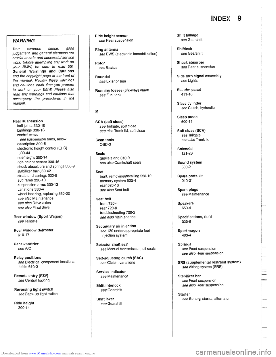
INDEX 9
WARNING
Your common sense, good judgemenl, and general alerlness are
crucial lo seie end successful service
ivork. Beiore attempting any work on
your
BMW be sure to read 001
General Warnings and Cautions and llle copyright page at lhe iron1 of
the manual. Review Niese warnings
and caulions each lime you prepare
lo work on your BMW Please also
read any warnings and caulions lllal accompany the procedures in the
manual.
Rear suspension
ball joints
330-19
bushings 330-13
control arms
seesuspension arms, below
description
300-5
electronic height control (EHC)
330-44
ride height 300-14 ride height sensor 330-46
shoclr absorbers end springs 330-9
stabilizer bar 330-42
struts and springs 330-5 subframe 330.13
suspension arms 330-13
variations 330-4 wheel bearing, replacing 330-32
see also Maintenance
see also Drive axles
see also Final drive
Rear window (Sport Wagon)
see
Tailgate
Rear window defroster 610-17
Receiverldrter
see NC
Relay positions
see Electrical component tocations
table 610-3
Remote entry (FZV)
see Central locking
Reversing light switch
see
Baclc-up light switch
Ride height
300-14
Ride height sensor
see Rear suspension
Ring antenna
see EWS (electronic immobilizalion)
Rotor
see Brakes
Roundel see Exterior trim
Running tosses
(312-way) valve
see Fuel
tenlr
SCA (soft close)
seeTailgate, soft close
see also Trunk lid. soft close
Scan tools
OED-3
Seals gaskets and 010-9
see also Crankshaft seals
Seat front,
removing/instelling 520-10
memory system 520-4 rear 520-13
see also Seat belt
Seat beit front 720-4
rear 720-8
troubleshooting 7202
see also Maintenance
Secondary air injection
see 130 under appropriate
iuel
injection system
Selector shaft seat
see Manual transmission, oil
Seals
Self-adjusting ctulch (SAC)
see Clutch, variations
Service indicator see Maintenance
Shift interlock see Gearshift
Shift lever
see
Gearshift
Shift linkage see Gearshift
Shiftlock see Gearshilt
Shack absorber see Rear suspension
/ Side turn signal assembly
see Lights
Sill trim panel
411-10
Slave cylinder
see Clutch, lhydraulic
Steep mode
600-1 1
Soft close
(SCA) see Tailgate
see also
Trunk lid
Solenoid 121-23
Sound system
650-2
Spare parts kit
010-21
Spark plugs
see Maintenance
Speakers
650-4
Specifications, fluid
020-4
Sport wagon
400-4
Springs
see Front suspension
see also Rear suspension
SRS (supplemental restraint system)
see
Airbag system (SRS)
Stabilizer bar see Front suspension
see also Rear suspension
Starter see Battery, starter, alternator