tow BMW 525i 1999 E39 Owner's Guide
[x] Cancel search | Manufacturer: BMW, Model Year: 1999, Model line: 525i, Model: BMW 525i 1999 E39Pages: 1002
Page 618 of 1002
Downloaded from www.Manualslib.com manuals search engine
260-1 2
1 Driveshaft
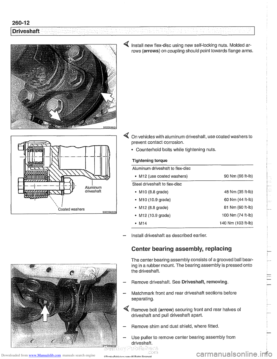
Install new flex-disc using new self-locking nuts. Molded ar-
rows (arrows) on coupling should point towards flange arms.
4 On vehicles with aluminum driveshaft, use coated washers to
prevent contact corrosion.
- Counterhold bolts while tightening nuts.
Tightening torque
Aluminum driveshaft to flex-disc
M12 (use coated washers) 90
Nm (66 ft-lb)
Steel driveshaft to flex-disc
MI0 (8.8 grade) 48
Nm (35 ft-lb)
- MI0 (10.9 grade) 60 Nm (44 ft-lb)
Coated washers - MI2 (8.8 grade) 5027500 . Mi2 (10.9 grade)
M14 81
Nm (60 ft-lb) 100 Nm (74 ft-lb)
140 Nm (103 ft-lb)
- Install driveshaft as described earlier
Center bearing assembly, replacing
The center bearing assembly consists of a grooved ball bear-
ing in a rubber mount. The bearing assembly is pressed
the driveshaft.
- Remove driveshaft. See Driveshaft, removing
- Matchmark front and rear driveshaft sections before
separating.
Remove bolt (arrow) securing front and rear halves of
driveshaft and pull driveshaft apart.
- Remove shim and dust shield, where fitted
- Use puller to remove center bearing assembly from
driveshaft. onto
Page 643 of 1002
Downloaded from www.Manualslib.com manuals search engine
Front ~us~ensionl
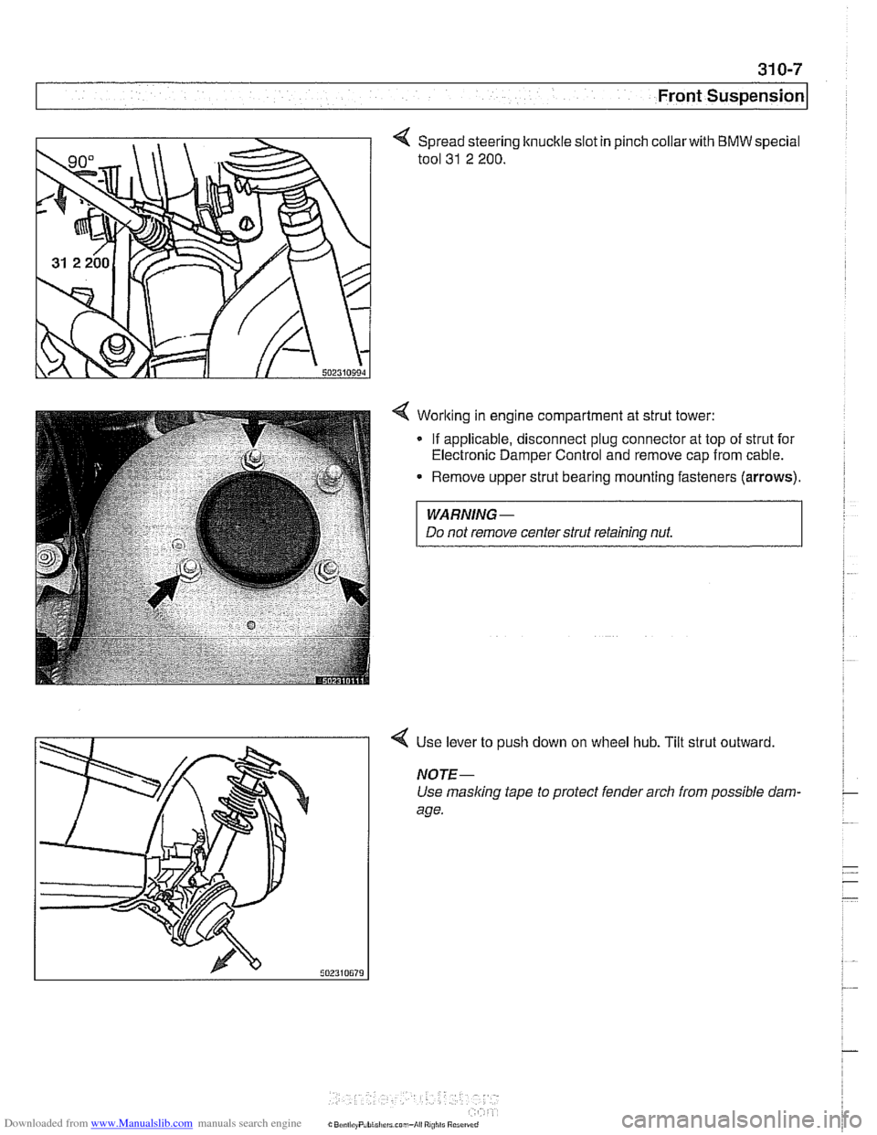
Spread steering knuckle slot in
tool
31 2 200.
pinch collarwith BMW special
4 Worlting in engine compartment at strut tower:
- If applicable, disconnect plug connector at top of strut for
Electronic Damper Control and remove cap from cable.
Remove upper strut bearing mounting fasteners
(arrows).
WARNING-
Do not remove centerstrut retaining nut.
4 Use lever to push down on wheel hub. Tilt strut outward
NOTE-
Use masking tape to protect fender arch from possible dam-
age.
Page 644 of 1002
Downloaded from www.Manualslib.com manuals search engine
31 0-8
Front Suspension
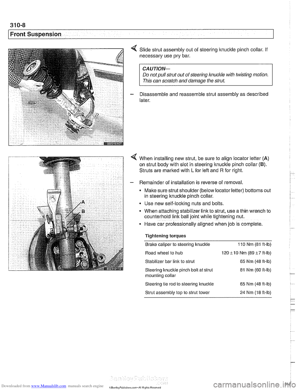
Slide strut assembly out of steering lknucltle pinch collar. If
necessary use pry bar.
CA UTIOI\C
Do notpullstrut out of steering knuckle with twisting motion.
This can scratch and damage the strut.
Disassemble and reassemble strut assembly as described
later.
When installing new strut, be sure to align locator letter (A)
on strut body with slot in steering
lknuckle pinch collar (6).
Struts are marked with L for left and R for right.
Remainder of installation is reverse of removal.
Make sure strut shoulder (below locator letter) bottoms out
in steering knuckle pinch collar.
Use new self-locking nuts and bolts.
When attaching stabilizer
lrnk to strut, use a thin wrench to
counterhold
link ball joint while t~ghtening nut.
- Have car professionally al~gned when job IS complete.
Tightening torques
Brake caliper to steering knuckle
110 Nm (81 ft-ib)
Road wheel to hub 120 ti0 Nm (89 t7 ft-lb)
Stabilizer bar
link to strut 65 Nm (48 It-lb)
Steering knucltle pinch bolt at strut 81 Nm (60 It-lb) - mountlng collar
Steering tle rod to steerlng knuckle 65 Nm (48 it-lb)
Strut assembly top to strut tower 24 Nm (18 it-lb)
- - -
Page 647 of 1002
Downloaded from www.Manualslib.com manuals search engine
Front Suspension
/ Front strut top mount assembly
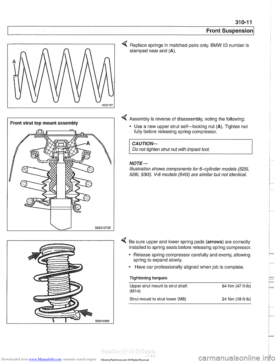
< Replace springs in matched pairs only. BMW ID number is
stamped near end
(A).
4 Assembly is reverse of disassembly, noting the following:
Use a new upper strut self-loclting nut
(A). Tighten nut
fully before releasing spring compressor.
CAUTION-
Do not tighten strut nut with impact tool.
NOTE-
illustration shows components for 6-cylinder models (5257,
528i, 5300. V-8 models (5400 are similar but not identical.
4 Be sure upper and lower spring pads (arrows) are correctly
installed to spring seats before releasing spring compressor.
Release spring compressor carefully and evenly, allowing
spring to expand slowly.
Have car professionally aligned when job is complete.
Tightening torques Upper strut mount to strut shaft
64 Nm (47 ft-lb)
Strut mount to strut tower (ME) 24 Nrn (18 fi-lb)
Page 718 of 1002
Downloaded from www.Manualslib.com manuals search engine
330-22
I Rear Suspension
s
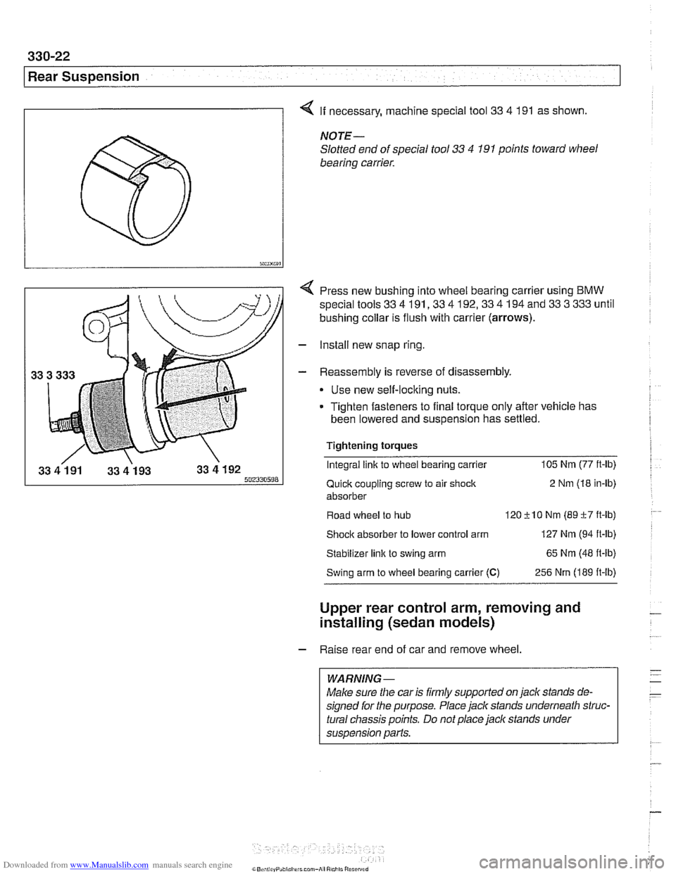
4 If necessary, machine special tool 33 4 191 as shown.
NOTE-
Slotted end of special tool 33 4 191 points toward wheel
bearing carrier.
Press new bushing into wheel bearing carrier using BMW
special tools
33 4 191,33 4 192,33 4 194 and 33 3 333 until
bushing collar is flush with carrier (arrows).
- Install new snap ring
- Reassembly is reverse of disassembly
Use new self-locking nuts.
Tighten fasteners to final torque only after vehicle has
been lowered and suspension has settled.
Tightening torques Integral link to wheel bearing carrier 105
Nm (77
ft-lb)
Quick coupling screw to air shock 2
Nm (18 in-ib)
absorber
Road wheel to hub
120+lO Nm (89c7ft-ib)
Shock absorber to lower control arm 127 Nm (94 ft-lb)
Stabilizer link to swing arm 65
Nm (48
fl-lb)
Swing arm to wheel bearing carrier (C) 256 Nrn (189 ft-lb)
Upper rear control arm, removing and
installing (sedan models)
- Raise rear end of car and remove wheel.
WARNING-
Make sure the car is firmly supported on jack stands de-
signed for the purpose. Place jack stands underneath struc-
tural chassis points. Do not place
jaclc stands under
suspension parts.
Page 724 of 1002
Downloaded from www.Manualslib.com manuals search engine
330-28
Rear Suspension
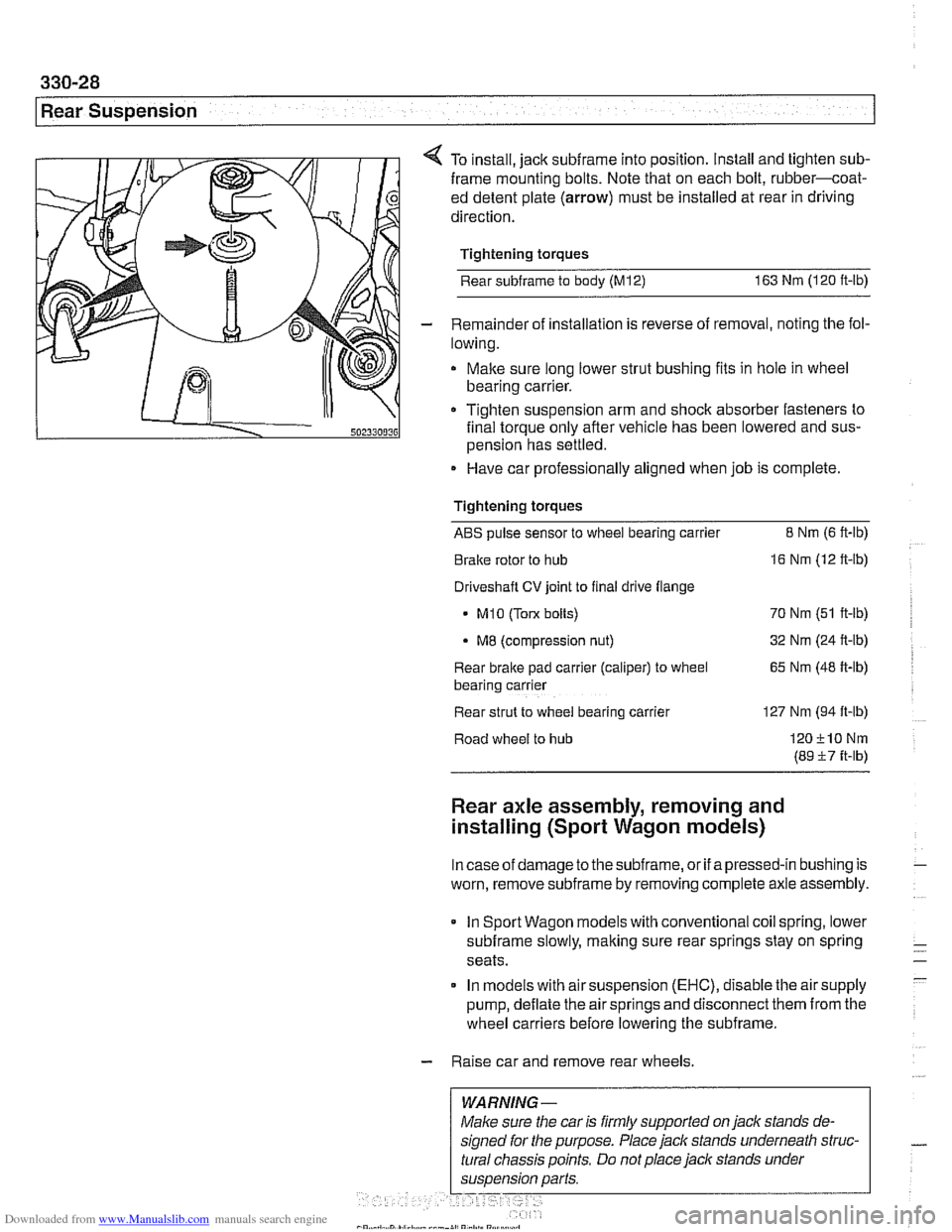
4 To install, jack subframe into position. Install and tighten sub-
frame mounting bolts. Note that on each bolt, rubber-coat-
ed detent plate
(arrow) must be installed at rear in driving
direction.
Tightening torques
Rear
subframe to body (M12) 163 Nm (120 ft-lb)
- Remainder of installation is reverse of removal, noting the fol-
lowing.
Make sure long lower strut bushing fits in hole in wheel
bearing carrier.
111 0 Tighten suspension arm and shoclc absorber fasteners to
502330036 final torque only afler vehicle has been lowered and sus-
pension has settled.
Have car professionally aligned when job is complete
Tightening torques
ABS pulse sensor to wheel bearing carrier 8 Nrn (6 ft-lb)
Brake rotor to hub
16 Nm (12 ft-lb)
Driveshaft
CV joint to final drive flange
- MI0 (Tow bolts) 70 Nm (51 ft-lb)
MB (compression nut) 32
Nm (24 ft-lb)
Rear brake pad
carrler (caliper) to wheel 65 Nm (48 ft-lb)
bear~ng carrler
Rear strut to
wheel bearlng carrler 127 Nm (94 ft-lb)
Road wheel to hub
120210Nrn
(89 57 ft-lb)
Rear axle assembly, removing and
installing (Sport Wagon models)
Incaseof damage to thesubframe, or if apressed-in bushing is
worn, remove
subframe by removing complete axle assembly.
In Sport Wagon models with conventional coil spring, lower
subframe slowly, making sure rear springs stay on spring
seats.
In models with air suspension
(EHC), disable the air supply
pump, deflate the air springs and disconnect them from the
wheel carriers before lowering the subframe.
- Raise car and remove rear wheels.
WARNING-
Page 782 of 1002
Downloaded from www.Manualslib.com manuals search engine
Brakes
- Pump brake pedal a few times to reduce vacuum in brake
booster. This makes removal of
check valve easier.
- Remove or loosen hose clamp(s) at check valve.
- Disconnect hoses. Remove valve to test or replace.
NOTE-
If valve is pressed into grommet in vacuum booster, pry it out
carefully.
- Reinstall valve using new hose clamps
NOTE-
Install the valve so that the molded arrow is pointing toward
the intake manifold.
Brake booster, removing and installing
CAUTIO&
All E39 vehicles sold in the USA are equipped with Antiloclc
Braking System (ABS) and either Automatic Stability Control
(ASC) or Dynamic Stability Control (DSC). In order for the
bralchg and stability controls to work properk if brake fluid
lines are disconnected and reconnected,
male sure that the
brake system is bled by an authorized BMW dealer or other
qualified repair facility using the BMW Service Tester: See
Brake Bleeding earlier in this group.
- Disconnect negative (-) cable from battery.
I CAUTION- I
Prior to disconnecting the battery read the battery discon-
nection cautions given in
001 General Cautions and
I Warnings. I
- Remove bralte master cylinder as described earlier.
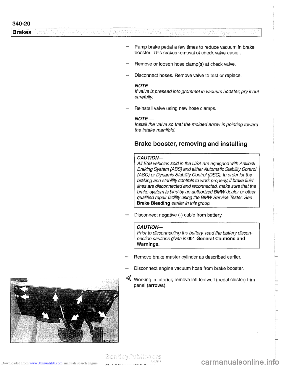
- Disconnect engine vacuum hose from bralte booster.
Page 839 of 1002
Downloaded from www.Manualslib.com manuals search engine
Trunk Lid, Tailgate
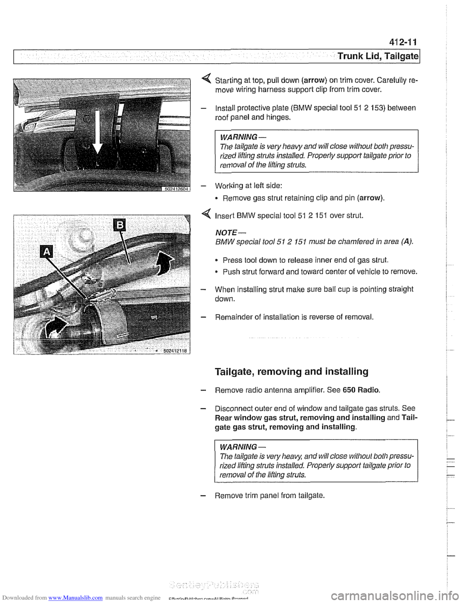
Starting at top, pull down (arrow) on trim cover. Carefully re-
move wiring harness support clip from trim cover.
Install protective plate
(BMW special tool 51 2 153) between
roof panel and hinges.
WARNING -
The tailgate is very heavy and will close without both pressu-
rized lifting
struts installed. Properly support tailgate prior to
removal of the lifting struts.
Worlting at left side:
Remove gas strut retaining clip and pin (arrow).
4 Insert BMW special tool 51 2 151 over strut.
NOTE-
BMW special tool 51 2 151 must be chamfered in area (A).
Press tool down to release inner end of gas strut.
Push strut forward and toward center of vehicle to remove.
- When installing strut make sure ball cup is pointing straight
down.
- Remainder of installation is reverse of removal.
Tailgate, removing and installing
- Remove radio antenna amplifier. See 650 Radio.
- Disconnect outer end of window and tailgate gas struts. See
Rear window gas strut, removing and installing and Tail-
gate gas strut, removing and installing.
WARNING-
The tailgate is very heaq and will close without both pressu-
rized lifling struts installed. Properly support tailgate prior to
removal of the lifling struts.
- Remove trim panel from tailgate.
Page 840 of 1002
Downloaded from www.Manualslib.com manuals search engine
Trunk Lid, Tailgate I
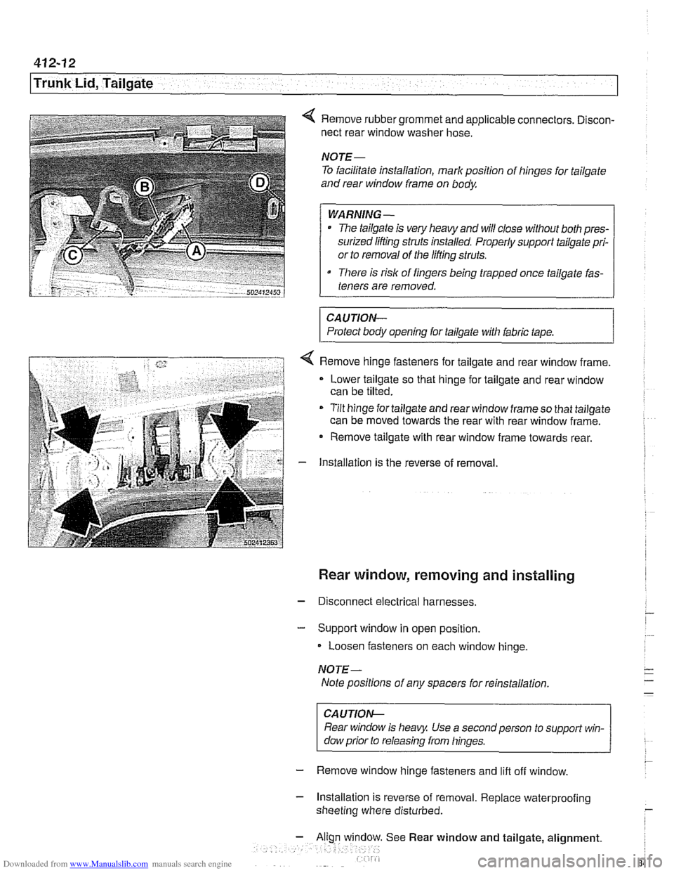
4 Remove rubber grommet and applicable connectors. Discon-
nect rear window washer hose.
NOTE-
To facilitate installation, mark position of hinges for tailgate
and rear window frame on body
WARNING-
The tailgate is very heavy and will close without both pres-
surized lifting struts installed. Properly support tailgate pri-
or to removal of the lifting struts.
There is risk of fingers being trapped once tailgate fas-
teners are removed.
CAUTION-
Protect body opening for tailgate with fabric tape.
4 Remove hinge fasteners for tailgate and rear window frame.
Lower tailgate so that hinge for tailgate and rear window
can be tilted.
- Tilt hinge for tailgate and rear window frame so that tailgate
can be moved towards the rear with rear window frame.
- Remove tailgate with rear window frame towards rear.
- Installation is the reverse of removal
Rear window, removing and installing
- Disconnect electrical harnesses.
- Support window in open position.
Loosen fasteners on each window hinge.
NOTE-
Note positions of any spacers for reinstallation
CAUTION-
Rear window is heavy Use a second person to support win-
dow prior to releasing from hinges.
- Remove window hinge fasteners and lift off window.
- Installation is reverse of removal. Replace waterprooiing
sheeting where disturbed.
See Rear window and tailgate, alignment.
Page 856 of 1002
Downloaded from www.Manualslib.com manuals search engine
51 0-6
Exterior Trim, Bumpers
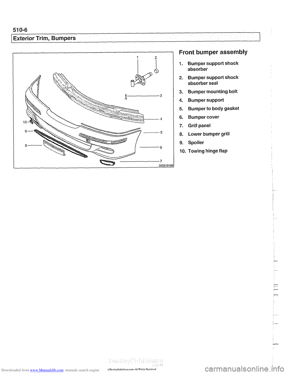
Front bumper assembly
1. Bumper support shock
absorber
2. Bumper support shock absorber seal
3. Bumper mounting bolt
4. Bumper support
5. Bumper to body gasket
6. Bumper cover
7. Grill panel
8. Lower bumper grill
9. Spoiler
10. Towing hinge flap