tow BMW 525i 1999 E39 Service Manual
[x] Cancel search | Manufacturer: BMW, Model Year: 1999, Model line: 525i, Model: BMW 525i 1999 E39Pages: 1002
Page 870 of 1002
Downloaded from www.Manualslib.com manuals search engine
Door Windows
Window anti-trap strip, testing
- To test function of anti-trap strip on any window:
With key
ON and window down, pull up window switch to
second detent, thus activating one-touch close operation.
Insert wooden block or other soft object between glass
and upper door frame.
Window should contact block, then immediately reverse
direction and lower by approximately
25 mm (1 in).
NOTE-
Anti-trap strip is integrated into the molding strip of the door
window frame.
Front window anti-trap strip, removing
- Remove front door panel and vapor barrier as described in
411 Doors.
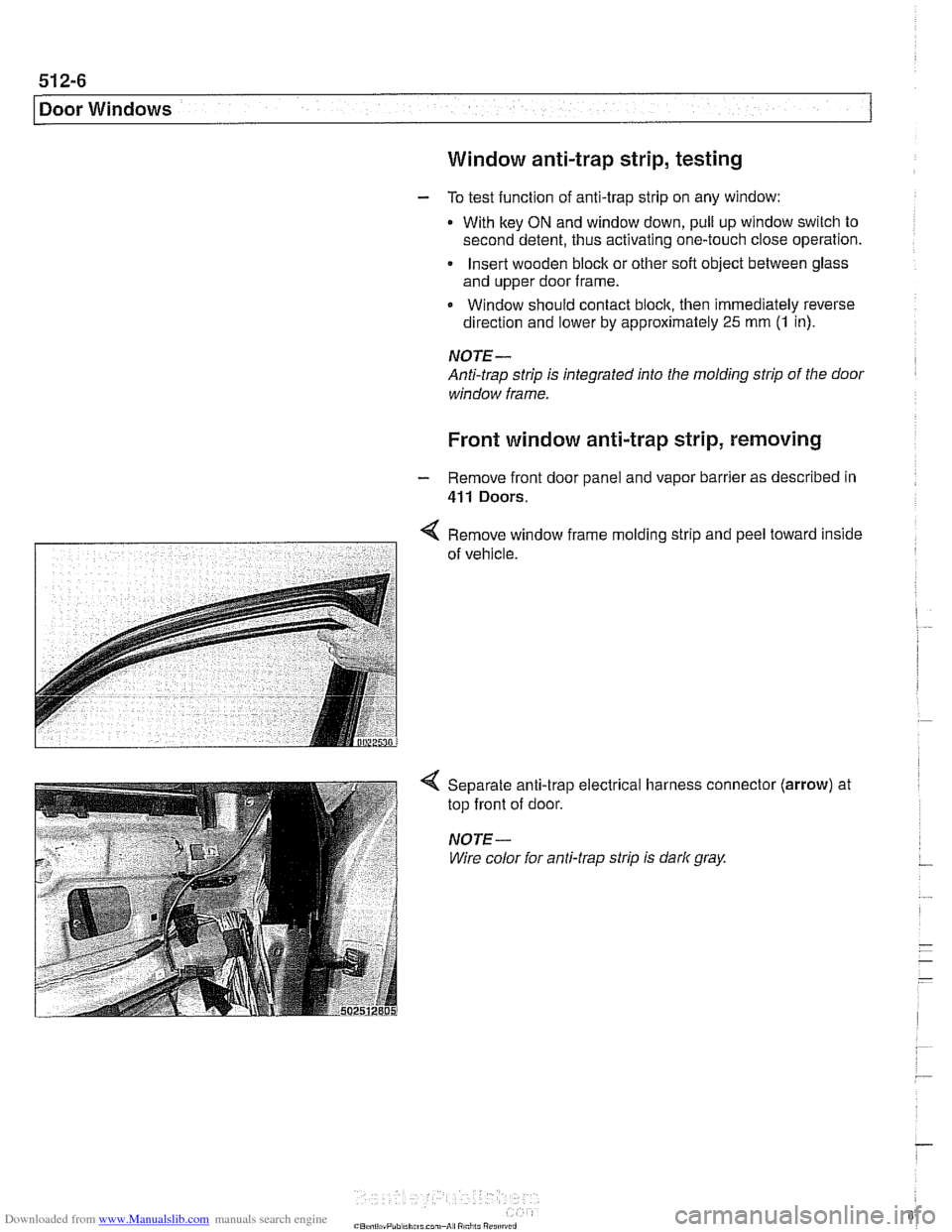
< Remove window frame mold~ng strlp and peel toward inside
7 of vehrcle.
Separate anti-trap electrical harness connector
top front of door.
NOTE-
Wire color for anti-trap strip is dark gray.
(arrow) at
Page 910 of 1002
Downloaded from www.Manualslib.com manuals search engine
51 5-1 6
Central Locking and Anti-Theft
DOOR HANDLES AND LOCKS
In the procedures that follow, door handle removal, door lock
cylinder removal and door latch removal are covered for the
left front door. Other doors are similar although simpler, due
to the
lack of lock cylinder.
Inside door release removal is covered in the procedure for
inner door
ane el removal. See 411 Doors.
Door handle (outer), removing and
installing
NOTE-
IfBMWspecial tools 51 3201 and51 3 203 are available, the
door handle can be removed without removing the door trim
panel or door
airbag. Use the access hole behind the rubber
sealing plug on the door edge.
- Close window on front door.
- Disconnect battery negative (-) cable.
CAUTlOG
Prior to disconnecting the batter)! read the battery discon-
nection cautions given
in 001 General Warnings and Cau-
tions.
Remove front door trim panel. See 411 Doors.
Remove door-mounted air bag. See 721
Airbag System
(SRS).
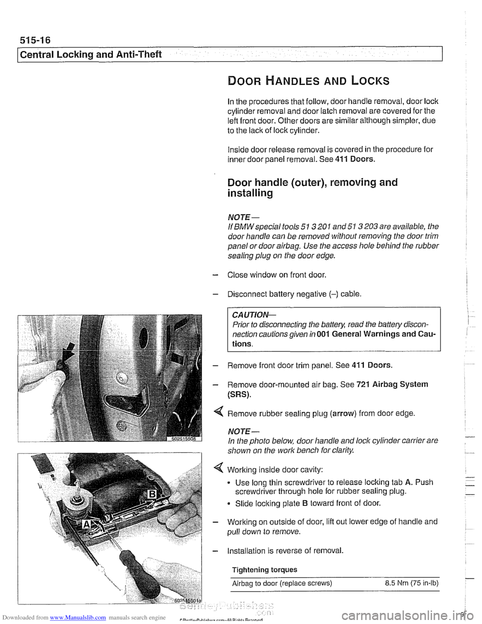
Remove rubber sealing plug (arrow) from door edge
NOTE-
In the photo below, door handle and lock cylinder carrier are
shown on the work bench for clarity.
Working inside door cavity:
- Use long thin screwdriver to release locking tab A. Push
screwdriver through hole for rubber sealing plug.
Slide locking plate
B toward front of door.
Working on outside of door, lift out lower edge of handle and
pull down to remove.
Installation is reverse of removal,
Tightening torques
Airbag to door (replace screws) 8.5 Nrn (75 in-lb)
Page 918 of 1002
Downloaded from www.Manualslib.com manuals search engine
51 5-24
l~entral Locking and Anti-Theft
ANTI-THEFT SYSTEM (DWA)
When the anti-then system (DWA) is armed, the doors, hood,
windows, trunk lid or tailgate are monitored against forcible
entry by switches and sensors. The vehicle is protected
against being jacked up or towed away by a tilt sensor.
The control electronics for DWA are integrated in the General
Module (GM). In addition to the control electronics, the sys-
tem includes the following components.
* DWA horn
DWA LED indicator
- Tilt sensor
- Monitoring switches and sensors
The system can be armed or disarmed from the driver's door
lock,
trunklid lock, tailgate lockorthe remote transmitter (FZV
Itey). When armed, the alarm horn
soundsfor30seconds and
the low beam headlights and turn signals flash for
5 minutes.
The electronic immobilizer (EWS) is also activated when
DWA is activated.
The alarm is switched off immediately if key is inserted in door
loclt or FZV key button is used.
DWA LED Status
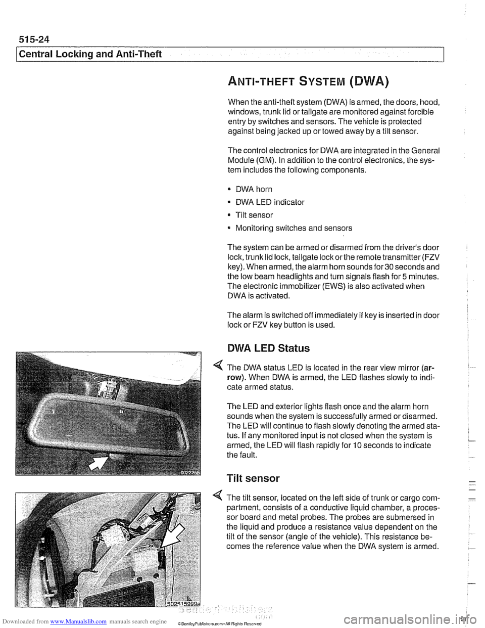
The DWA status LED is located in the rear view mirror (ar-
row). When DWA is armed, the LED flashes slowly to indi-
cate armed status.
The LED and exterior lights flash once and the alarm horn
sounds when the system is successfully armed ordisarmed.
The LED will continue to flash slowly denoting the armed sta-
tus. If any monitored input is not closed when the system is
armed, the LED will flash rapidly for
10 seconds to indicate
the fault.
Tilt sensor
-
4 The tilt sensor, located on the left side of trunlt or cargo com- -
partment, consists of a conductive liquid chamber, a proces-
sor board and metal probes. The probes are submersed in
the liquid and produce a resistance value dependent on the
tilt of the sensor (angle of the vehicle). This resistance be-
comes the reference value when the DWA system is armed.
.-
Page 955 of 1002
Downloaded from www.Manualslib.com manuals search engine
Airbag System (SRS)~
MRS control module, replacing
- Disconnect negative (-) cable from battery and cover nega-
tive terminal with insulating material.
CAUTIOI\C
Prior to disconnecting the battery, read the battery discon-
nection cautionsgiven in001 General Warnings and
Cau-
tions.
- Remove center console between front seats. See 513 lnteri-
or Trim.
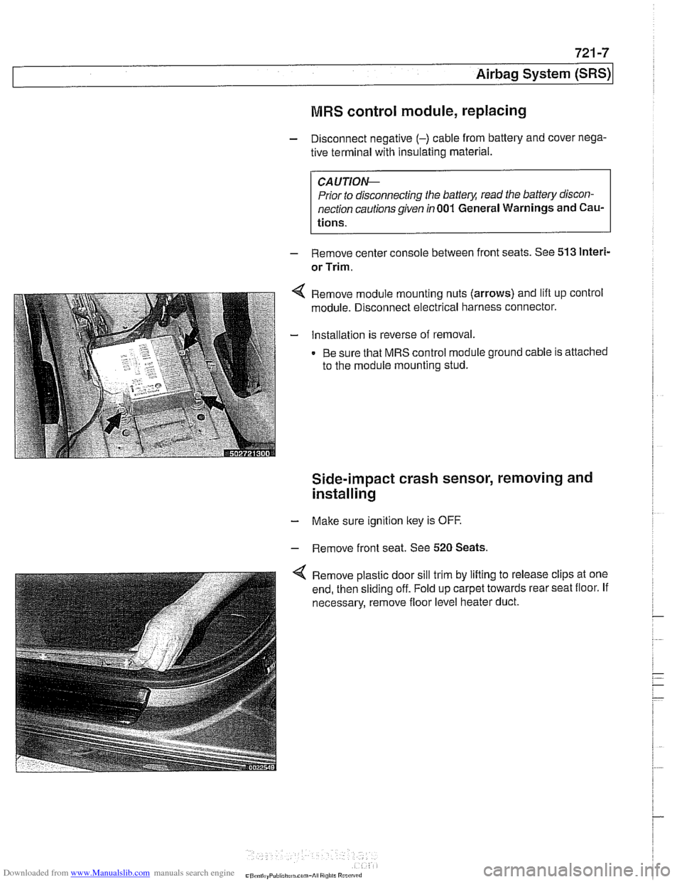
Remove module mounting nuts (arrows) and lift up control
module. Disconnect electrical harness connector.
Installation is reverse of removal.
Be sure that MRS control module ground cable is attached
to the module mounting stud.
Side-impact crash sensor, removing and
installing
- Make sure ignition key is OFF.
- Remove front seat. See 520 Seats.
Remove plastic door sill trim by lifting to release clips at one
end, then sliding off. Fold up carpet towards rear seat floor. If
necessary, remove floor level heater duct.
Page 1001 of 1002
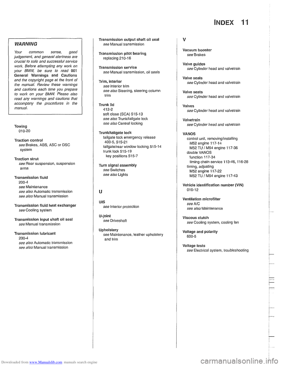
Downloaded from www.Manualslib.com manuals search engine
WARNING
Your common sense, good
judgement, and general alertness are
crucial to saie and
successiul sewice
work. Beiore attempting any work on
your BMW be sure to read 001
General Warnings and Cautions
and the copyright page
a1 the iront of
the manual. Review tliese warnings
and cautions each time you prepare
to work on your
BMW. Please also
read any warnings and
cautions that
accompany the procedures in the
manual.
Towing 010-20
Traction control
see Brakes, ABS, ASC or DSC
system
Traction strut
see Rear suspension, suspension
arms
Transmission fluid
200-4
see Maintenance
see also Automatic transmission
see also Manuai transmission
Transmission
fluid heat exchanger
see Cooling system
Transmission input shaft oil seat
see Manual transmission
Transmission lubricant
200-4 see also Automatic transmission
see also Manual
lransmission
Transmission output shafl oil seal
see Manual transmission
Transmission pilot bearing
replacing 210-16
Transmission service see Manual transmission, oil seals
Trim, interior
see interior trim
see also Steering, steering column
trim
Trunk lid
412-2 soft close (SCA) 515-13
see also Trunkltailgale loci(
see also Central iocl
tailgate loci( emergency release
400-5, 515-21 tailgatelrear window locl(ing 515-14
trunk lock 51 5-1 9
lrey positions 515-7
Turn signai assembly
see Switches
see also Lights
UIS see Interior protection
U-joint
see Driveshaft
Upholstery see Maintenance, leather upholstery
and trim Vacuum
booster
see Brakes
Valve guides
see Cylinder
head and valvetrain
Valve seals
see Cylinder head and valvetrain
Valve seats
see Cylinder head and valvetrain
Valves see Cylinder head and
vaivelrain
Valvetrain see Cylinder head and valvetrain
VANOS control unit,
removinglinstalling
M52 engine 117-14
M52 TU i M54 engine 117-36 double VANOS
function
117-34 timing chain service 113-46. 116-28
timing, adjusting
M52 engine 117-22
M52 TU l M54 engine 117-43
Vehicle identification number (VIN)
010-12
Ventilation microfilter
see
AIC
see also Maintenance
Viscous clutch see Cooling
system, cooling tan
Voitage and polarity
600-5
Voltage tests
see Electrical system, troubleshooting