torque BMW 525i 1999 E39 Service Manual
[x] Cancel search | Manufacturer: BMW, Model Year: 1999, Model line: 525i, Model: BMW 525i 1999 E39Pages: 1002
Page 166 of 1002
Downloaded from www.Manualslib.com manuals search engine
/Cylinder Head Removal and Installation
- Remainder of installation is reverse of removal, noting the fol-
lowing:
Use new gaskets when mounting intake
manifold. Tighten
nuts finger tight first, then torque to specification in stages
working diagonally from center out.
Be sure to reinstall ignition coil ground straps at cylinders
no.
3 and no. 7. See 120 Ignition System.
Reinstall cooling fan and shroud. See
170 Radiator and
Cooling System.
Refill and bleed cooling system as described in
170 Radi-
ator and Cooling System.
Change engine oil and filter as described in
020 Mainte-
nance.
CA UTIOG
To prevent damaging engine electricalsystems, be sure to in-
stall all ground wires previously removed.
Tightening torques
Camshaft sprocket to camshaft 15
Nm (11 H-lb)
Coolant manifold to cylinder head 10 Nm (7.5 H-lb)
Cylinder head cover nuts 10 Nm (7.5 ft-lb)
Exhaust manifold to head 22 Nm (17 ft-lb)
Engine mounts to subirame 42 Nm (30 ft-lb)
Spark plugs to cylinder head 22 Nm (17 ft-lb)
Right cylinder head, removing, M62 engine
- Remove left side exhaust manifold. See 180 Exhaust Sys-
tem.
- Remove intake manifold. See Intake manifold, removal
and installation,
M62 engine.
- Drain engine coolant. See 170 Radiator and Cooling Sys-
tem.
WARNING-
Use extreme caution when draining and disposing of engine
coolant.
Coolanl is poisonous andlellial lo liumans andpels.
Pets are
altracled to coolant because of 11s sfieet smell and
fasle. Seelc medcal anenfion immed~alely if coolant is ingesl-
. .-
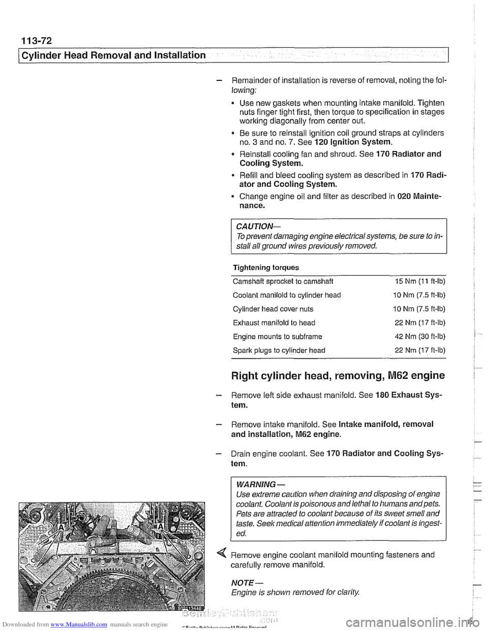
< Remove engine coolant manlold mo~nlng fasreners and
carei~lly remove manifo d.
. I
NOTE
Engine 8s slioivn removed lor clarify
Page 171 of 1002
Downloaded from www.Manualslib.com manuals search engine
Cvlinder Head Removal and Installation /
Right cylinder head, installing, M62 engine
- Clean cylinder head and block sealing surfaces of gasket de-
bris, making sure no debris drops into coolant or oil passag-
es.
CA UTIOW-
To prevent valve to piston contact when tightening camshaft
sprocket fasteners, counterhold camshaft with
27 mm open-
end wrench. If
necessarq: grind outer side of wrench jaws to
prevent damaging cylinder head.
- Check cylinder head bolt holes and condition of threads. Re-
move debris and liquids from holes.
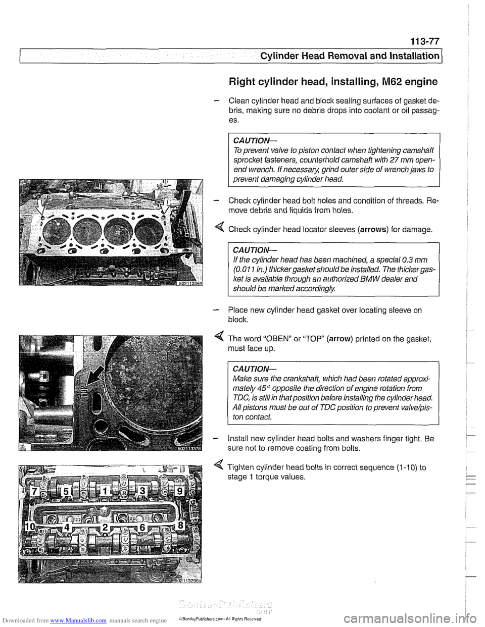
4 Check cylinder head locator sleeves (arrows) for damage
CAUTION-
lithe cylinder head has been machined, a special 0.3 rnm
(0.01 1 in.) thickergasket should be installed. The thickergas-
ket is available through an authorized BMW dealer and
should be marked
accordinglw
- Place new cylinder head gasket over locating sleeve on
block.
< The word "OBEN" or "TOP (arrow) printed on the gasket.
must face up.
CAUTION-
Male sure the crankshaft, which had been rotated approxi-
mately
45" opposite the direction of engine rotation from
TDC, is
stillin thatposition before installing the cylinder head.
All pistons must be out of
TDCposition to prevent valve/pis-
ton contact
- Install new cylinder head bolts and washers finger tight. Be
sure not to remove coating from bolts.
4 Tighten cylinder head bolts in correct sequence (1 -10) to
stage
1 torque values.
Page 172 of 1002
Downloaded from www.Manualslib.com manuals search engine
11 3-78
Cylinder Head Removal and Installation
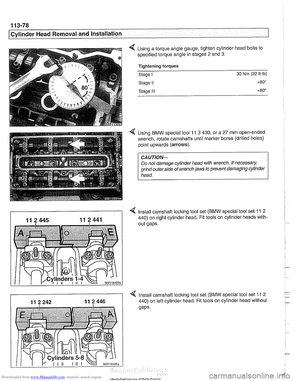
4 Using a torque angle gauge, tighten cylinder head bolts to
specified torque angle in stages
2 and 3.
Tiahtenina toraues - -.
Stage I 30 Nm (22 ft-lb)
Stage I1
Stage Ill
4 Using BMW special tool 11 3 430, or a 27 mm open-ended
wrench, rotate camshafts until marker bores (drilled holes)
point upwards
(arrows).
Do not damage cylinder head with wrench. If necessary.
grind outer side of wrench jaws to prevent damaging cylinder
head.
4 Install camshaft locking tool set (BMW special tool set 11 2
440) on right cylinder head. Fit tools on cyllnder heads with-
out gaps.
4 Install camshaft locking tool set (BMW special tool set 11 2
440) on left cylinder head. Fit tools on cylinder head without
Page 174 of 1002
Downloaded from www.Manualslib.com manuals search engine
11 3-80
Cylinder Head Removal and lnstallation
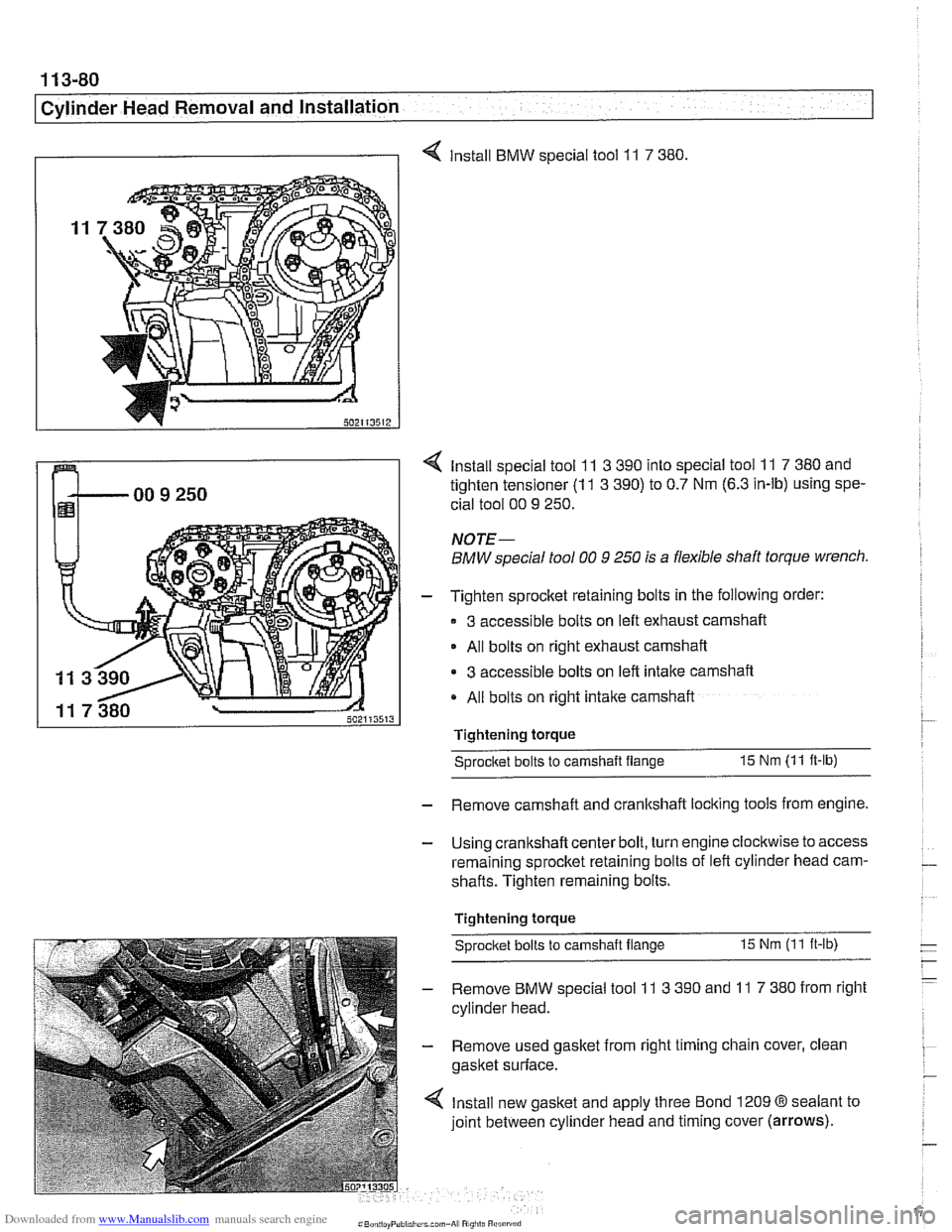
I I 4 Install BMW special tool 11 7 380
4 Install special tool 11 3 390 into special tool 11 7 380 and
tighten tensioner
(1 1 3 390) to 0.7 Nm (6.3 in-lb) using spe-
cial tool 00
9 250.
NOTE-
BMW special tool 00 9 250 is a flexible shaft torque wrench.
- Tighten sprocket retaining bolts in the following order:
3 accessible bolts on left exhaust camshaft
- All bolts on right exhaust camshaft
3 accessible bolts on left intake camshaft
All bolts on right intake camshaft
Tightening torque
Sprocitet bolts to camshaft flange 15 Nm (11 ft-lb)
- Remove camshaft and crankshaft locking tools from engine.
- Using crankshaft center bolt, turn engine clockwise to access
remaining sprocket retaining bolts of left cylinder head cam-
shafts. Tighten remaining bolts.
Tightening torque
Sprocket bolts
to camshaft flange 15 Nm (11 ft-ib)
- Remove BMW special tool 11 3 390 and 11 7 380 from right
cylinder head.
- Remove used gasket from right timing chain cover, clean
gasket surface.
4 Install new gasket and apply three Bond 1209 @sealant to
joint between cylinder head and timing cover
(arrows).
Page 175 of 1002
Downloaded from www.Manualslib.com manuals search engine
Cylinder Head Removal and Installation 1
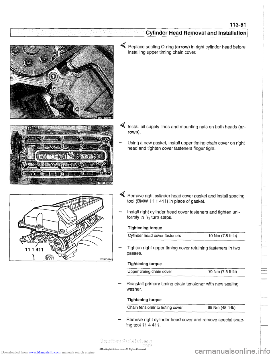
Replace sealing O-ring (arrow) in right cylinder head before
installing upper timing chain cover.
4 Install oil supply lines and mounting nuts on both heads (ar-
rows).
- Using a new gasket, install upper timing chain cover on right
head and tighten cover fasteners finger tight.
4 Remove right cylinder head cover gasket and install spacing
tool
(BMW 11 1 41 1) in place of gasket.
- Install right cylinder head cover fasteners and tighten uni-
formly in
'1, turn steps.
Tightening torque Cylinder head cover fasteners
10 Nm (7.5 ft-lb)
- Tighten right upper timing cover retaining fasteners in two
passes.
I Tightening torque
Upper timing chain cover
10 Nm (7.5 ft-lb)
- Reinstall primary timing chain tensioner with new sealing
washer.
Tightening torque
Chain tensioner to timing cover
65 Nm (48 ft-lb)
- Remove right cylinder head cover and remove special spac-
ingtooi 11 4411.
Page 176 of 1002
Downloaded from www.Manualslib.com manuals search engine
1 13-82
1 Cylinder Head Removal and Installation
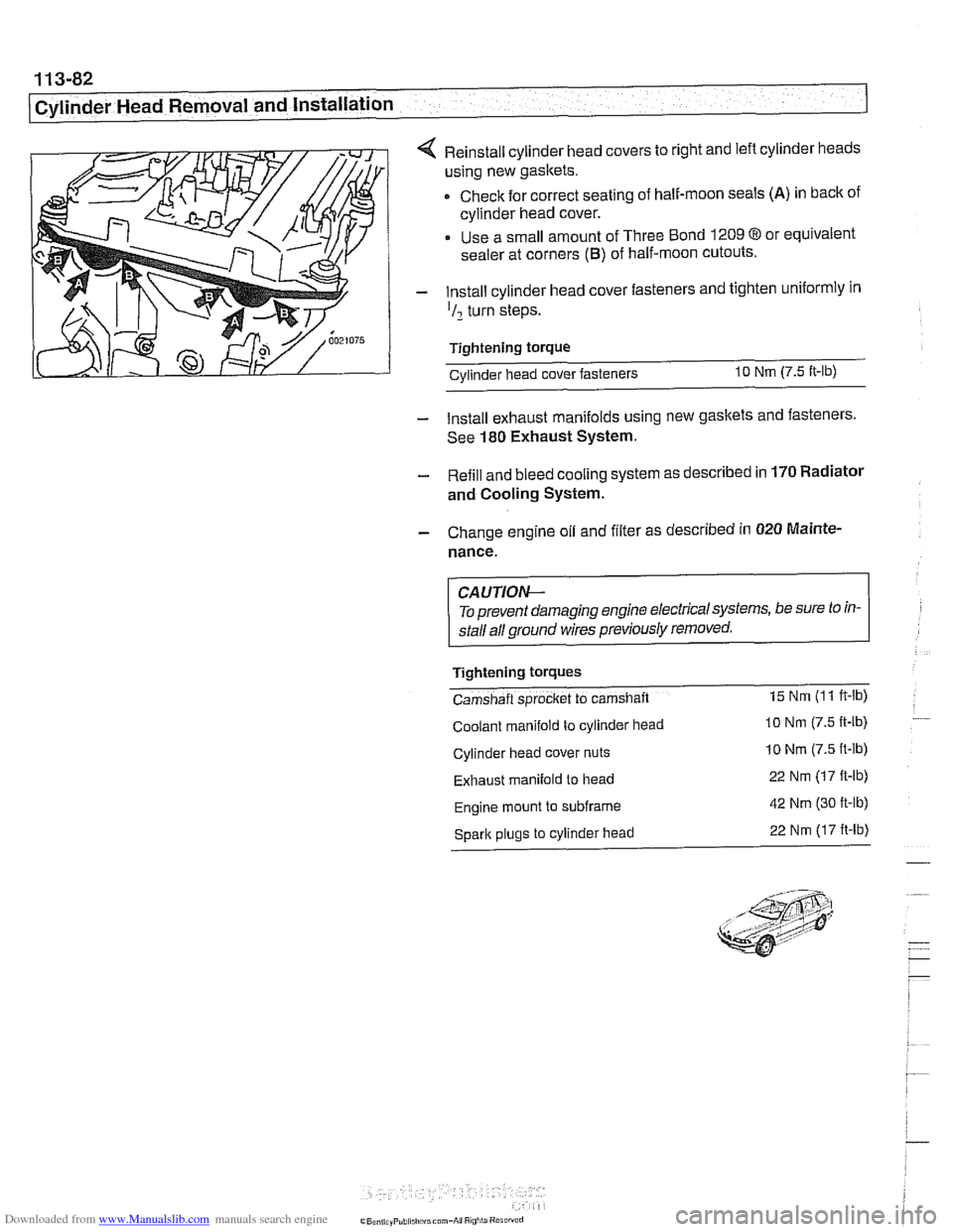
4 Reinstall cylinder head covers to right and left cylinder heads
using new gaskets.
Check for correct seating of half-moon seals
(A) in back of
cylinder head cover.
Use a small amount of Three Bond
1209 8 or equivalent
sealer at corners
(B) of half-moon cutouts.
- Install cylinder head cover fasteners and tighten uniformly in
'I2 turn steps.
Tightening torque Cvlinder head cover fasteners
10 Nm (7.5 It-lb)
- Install exhaust manifolds using new gaskets and fasteners.
See
180 Exhaust System.
- Refill and bleed cooling system as described in 170 Radiator
and Cooling System.
- Change engine oil and filter as described in 020 Mainte.
nance.
CA UTIOW-
To prevent damaging engine electricalsystems, be sure to in-
stall all ground wires previously removed.
Tightening
tOrqUeS
Camshaft sprocket to camshaft 15 Nm (1 1 ft-lb)
Coolant manifold to cylinder head lo Nm (7.5 It-lb)
Cylinder head cover nuts 10 Nm (7.5 ft-lb)
Exhaust manifold to head 22 Nm (17 ft-lb)
Engine mount to subframe 42 Nm (30 ft-lb)
Spark plugs to cylinder head 22 Nm (17 ft-lb)
Page 178 of 1002
Downloaded from www.Manualslib.com manuals search engine
This group covers cylinder head and valvetrain service and
repair. Some of the repair procedures described here require
that the cylinder head first be removed as described in
113
Cylinder Head Removal and Installation.
NOTE- For timing chain and
VANOS repair information, see 117
Camshaft Timing Chain.
If it is
determined that the cylinder head will require signif-
icant reconditioning work, a remanufactured cylinder head
may be a good alternative. Remanufactured cylinder
heads are available from an authorized
BMW dealer.
The information given in this repair group is organized ac-
cording to engine code. For engine application information,
see
I00 Engine-General.
For specific repair procedures, refer to the appropriate repair
group:
* 020 Maintenance
100 Engine-General
113 Cylinder Head Removal and Installation
117 Camshafi Timing Chain
= 170 Radiator and Coo!ing System
Special Tools
Special BMW tools are required for most cylinder head ser-
vice described in this repair group. Many of these tools are ex-
pensive and only available through an authorized
BMW
dealer. If the special tools are not available, have the cylinder
head removed and disassembled by an authorized BMW
dealer. Be sure to read each procedure thoroughly before
starting a job to determine which special tools and equipment
will be necessary.
Most of the repairs to a cylinder head require precision
rna-
chine work to specific tolerances. This type of work should be
performed by an authorized BMW repairfacility or an ASE
certified machinist.
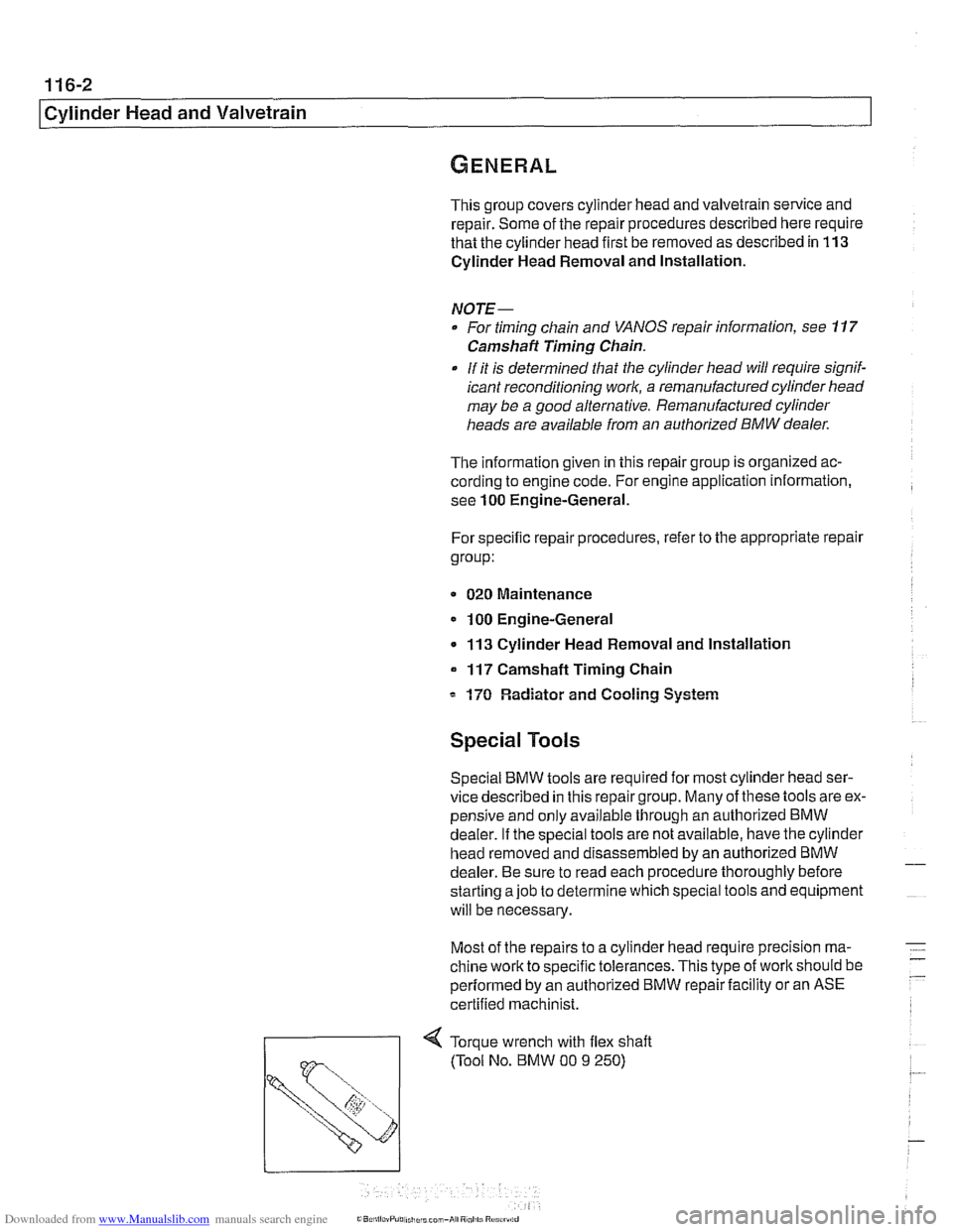
71 Torque wrench with flex shaft
Page 187 of 1002
Downloaded from www.Manualslib.com manuals search engine
Cylinder Head and Valvetrain
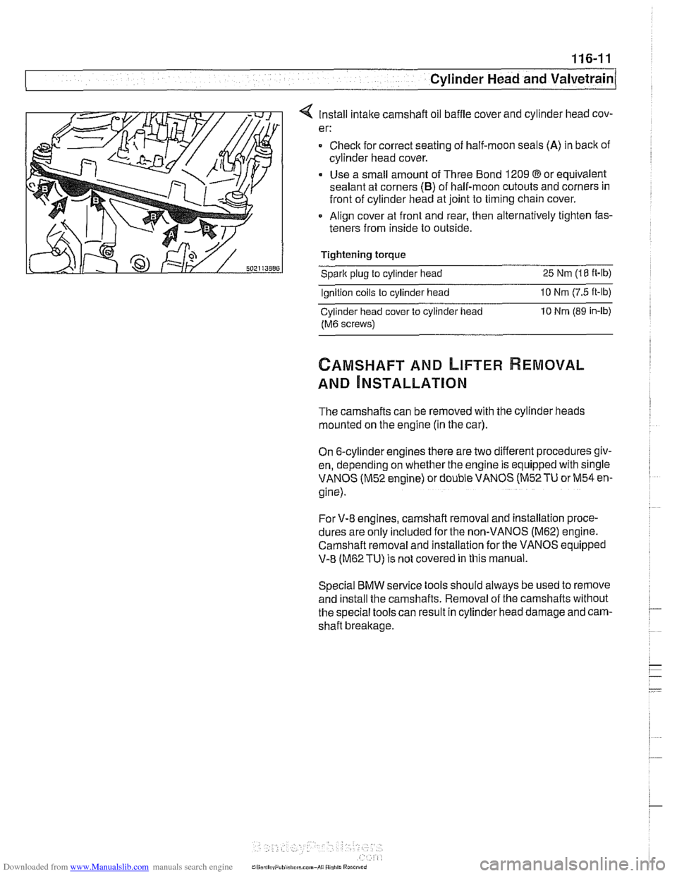
4 Install intake camshaft oil baffle cover and cylinder head cov-
er:
= Checlc for correct seating of half-moon seals (A) in back of
cylinder head cover.
Use a small amount of Three Bond 1209
@or equivalent
sealant at corners
(B) of half-moon cutouts and corners in
front of cylinder head at joint to timing chain cover.
Align cover at front and rear, then alternatively tighten fas-
teners from inside to outside.
Tightening torque
Sparic plug to cylinder head 25 Nm (18 it-lb)
Ignition coils to cylinder head 10 Nrn (7.5 ft-lb)
Cylinder head cover to cylinder iiead 10 Nrn (89 in-lb)
fM6 screws)
CAMSHAFT AND LIFTER REMOVAL
AND ~NSTALLATION
The camshafts can be removed with the cylinder heads
mounted on the engine (in the car).
On 6-cylinder engines there are two different procedures giv-
en, depending on whether the engine is equipped with single
VANOS (M52 engine) or double VANOS
(M52TU or M54 en-
gine).
For V-8 engines, camshaft removal and installation proce-
dures are
only included for the non-VANOS (M62) engine.
Camshaft removal and installation for the
VANOS eq;ipped
V-8 (M62TU) is not covered in this manual.
Special BMW service tools should always be used to remove
and install the camshafts. Removal of the camshafts without
the special tools can result in cylinder head damage and cam-
shaft breakage.
Page 192 of 1002
Downloaded from www.Manualslib.com manuals search engine
.
Cylinder Head and Valvetrain
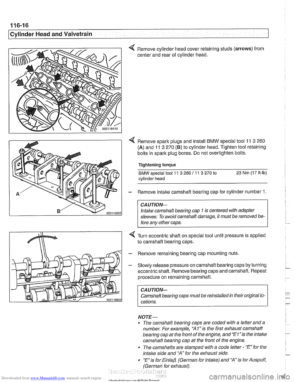
< Remove cylinder head cover retaining studs (arrows) from
center and rear of cylinder head.
< Remove spark plugs and install BMW special tool 11 3 260
(A) and 11 3 270 (6) to cylinder head. Tighten tool retaining
bolts in spark plug bores. Do not overtighten bolts.
Tightening
torque
BMW special tool 11 3 260 I1 1 3 270 to 23 Nm (17 It-lb)
cylinder head
- Remove intake camshaft bearing cap for cylinder number 1.
CA UTIOG
Intake camshaft bearing cap 1 is centered with adapter
sleeves. To avoid
can~sllaft daniage, it must be removed bs-
fore any other caps.
Turn eccentric shaft on special tool until pressure is applied
to camshaft bearing caps.
- Remove remaining bearing cap mounting nuts
- Slowly release pressure on camshaft bearing caps by turning
eccentric shaft. Remove bearing caps and camshaft. Repeat
procedure on remaining camshaft.
CAUTION-
Camshaft bearing caps must be reinstalled in their original lo-
cations.
NOTE-
The camshaft bearing caps are coded with a letter anda
number. For example,
'XI" is the first exhaust camshaft
bearing cap at the front of the engine, and
"El "is the intalce
camshaft bearing cap at the front of the engine.
0 The camshafts are stamped with a code letter - "E" for the
intake side and 'MA" for the exhaust side.
0 "E is for Einlap, (German for intake) and 'XA"is for Auspuff,
(German for exhaust).
Page 195 of 1002
Downloaded from www.Manualslib.com manuals search engine
Cylinder Head and valvetrain1
- Remainder of installation is reverse of removal, noting the
following:
See
117 Camshaft Timing Chain for VANOS control unit
installation.
Tightening torques
Camshaft bearing caps
to cylinder head (M7) 15 Nm (1 1 ft-lb)
Cylinder head cover to cylinder head (M6) 10 Nm (89 in-lb)
Sparic plugs (M12) 23 Nm (17 ft-lb)
Camshaft and lifter, removal and
installation
(M52 TU and M54 engine)
Camshafts and lifters, removing
(M52 TU and M54 engine)
WARNING-
Allow engine fo cool before beginning this procedure.
- Disconnect negative (-) cable from battery.
CAUTION--
Prior to disconnecting the battea read the battery discon-
nection cautions in
001 General Cautions and Warnings.
Remove VANOS control unit. See 117 Camshaii Timing
Chain.
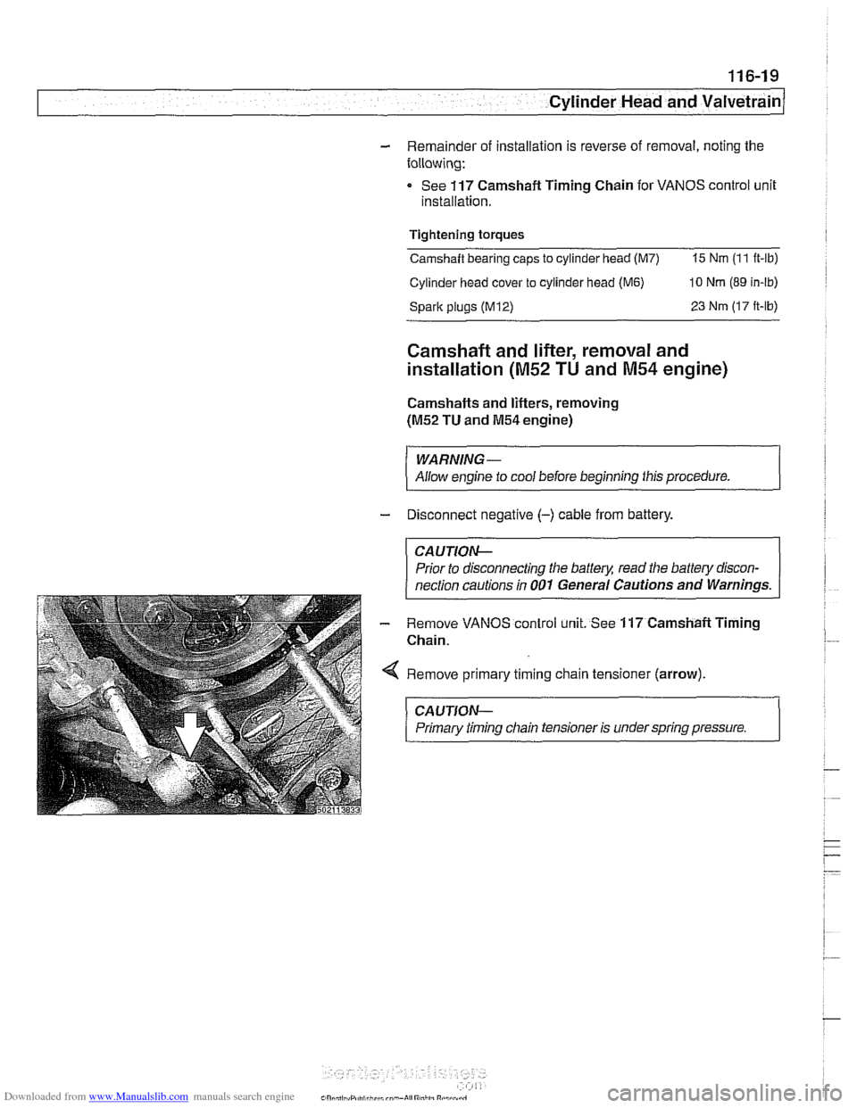
Remove primary timing chain tensioner (arrow).
CAUTION-
Primary timing chain tensioner is under spring pressure. 1