key BMW 525i 1999 E39 Workshop Manual
[x] Cancel search | Manufacturer: BMW, Model Year: 1999, Model line: 525i, Model: BMW 525i 1999 E39Pages: 1002
Page 36 of 1002
Downloaded from www.Manualslib.com manuals search engine
020-4
Maintenance
1997 to 2000 models
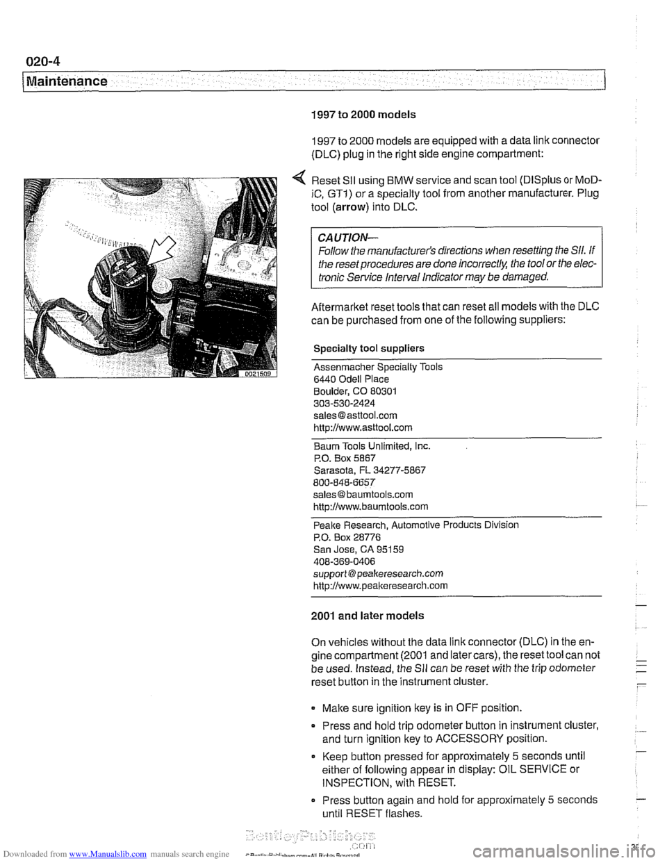
1997 to 2000 models are equipped with a data link connector
(DLC) plug in the right side engine compartment:
Reset
SII using BMW service and scan tool (DISplus or MoD-
iC, GTI) or a specialty tool from another manufacturer. Plug
tool (arrow) into DLC.
CAUTION-
Follow the manufacturer's directions when resetting the Sll. If
the reset procedures are done
incorrect& the tool or the elec-
tronic Service Interval Indicator
may be damaged.
Aftermarket reset tools that can reset all models with the DLC
can be purchased from one of the following suppliers:
Specialty tool suppliers
Assenmacher Specialty Tools
6440
Odell Place
Boulder, CO 80301
303-530-2424
[email protected] http://www.asttool.com
Baum Tools Unlimited,
Inc.
P.O. Box 5867
Sarasota, FL 34277-5867
800-848-6657
[email protected]
http://www.baumtools.com
Peake Research. Automotive Products Division
P.O. Box 28776
San Jose, CA 95159
408-369-0406
support @peakeresearch.com
http://www.peal~eresearch.com
2001 and later models
On vehicles without the data link connector (DLC) in the en-
gine compartment (2001 and latercars), the reset tool can not
be used. Instead, the
Sll can be reset with the trip odometer
reset button in the instrument cluster.
Make sure ignition key is in OFF position.
* Press and hold trip odometer button in instrument cluster,
and turn ignition key to ACCESSORY position.
Keep
button pressed for approximately 5 seconds until
either of following appear in display: OIL SERVICE or
INSPECTION, with RESET.
Press button again and
hold for approximately 5 seconds
until RESET flashes.
Page 243 of 1002
Downloaded from www.Manualslib.com manuals search engine
Camshaff Timing Chain
NOTE-
Mark direction of belt rotation if reusing belt.
- Remove vibration damper mounting bolts and remove vibra-
tion damper and pulley from hub.
NOTE- The M52
6-cylinder engine uses a 2-piece vibration damper
and hub assembly.
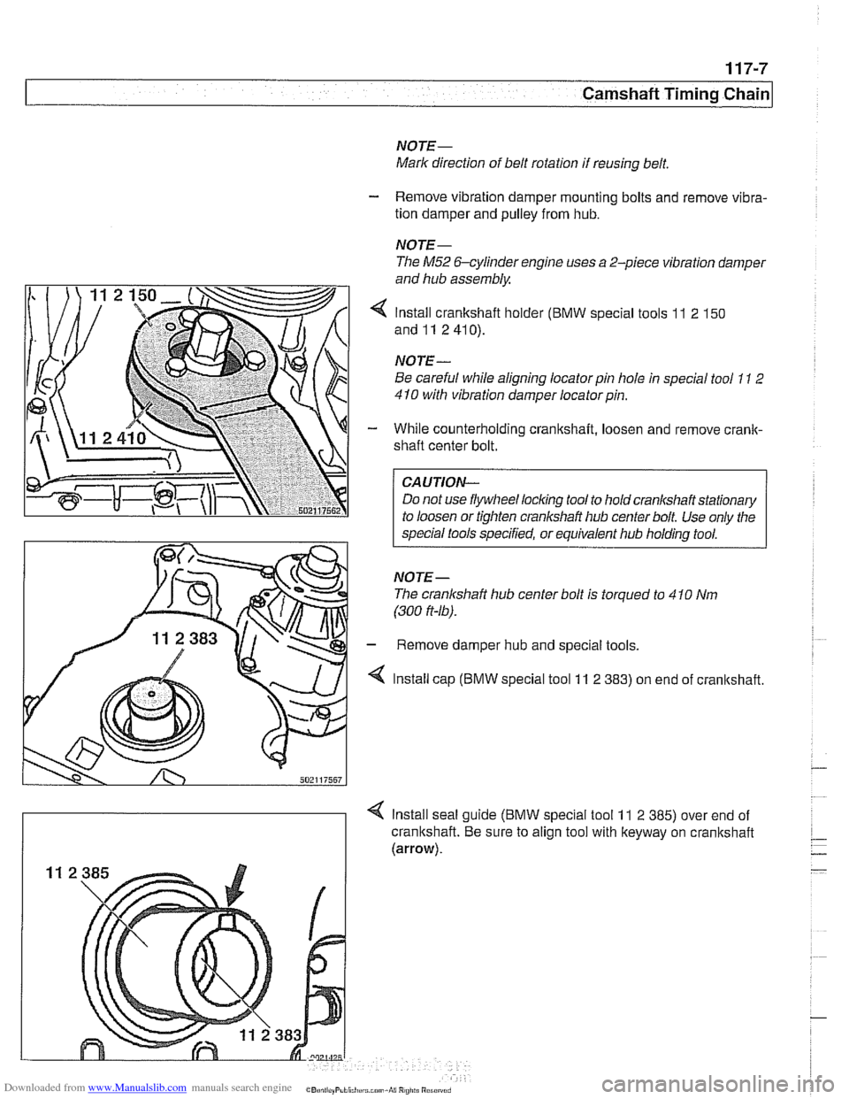
4 Install crankshaft holder (BMW special tools 11 2 150
and11 2410).
NOTE
-
Be careful while aligning locator pin hole in special tool 11 2
410 with vibration damper locatorpin.
- While counterholding crankshaft, loosen and remove crank-
shaft center bolt.
CAUTION-
Do not use flywheel locking tool to hold crankshaft stationary
to loosen or tighten crankshaft hub center bolt Use only the
special tools specified, or equivalent hub holding tool.
NOTE- The cranlshaft hub center bolt is torqued to 4
10 Nm
(300
ft-16).
- Remove damper hub and special tools.
4 Install cap (BMW special tool 11 2 383) on end of cranltshaft.
4 Install seal guide (BMW special tool 11 2 385) over end of
crankshaft. Be sure to align tool with keyway on crankshaft
(arrow).
Page 244 of 1002
Downloaded from www.Manualslib.com manuals search engine
1 17-8
Camshaft Timing Chain
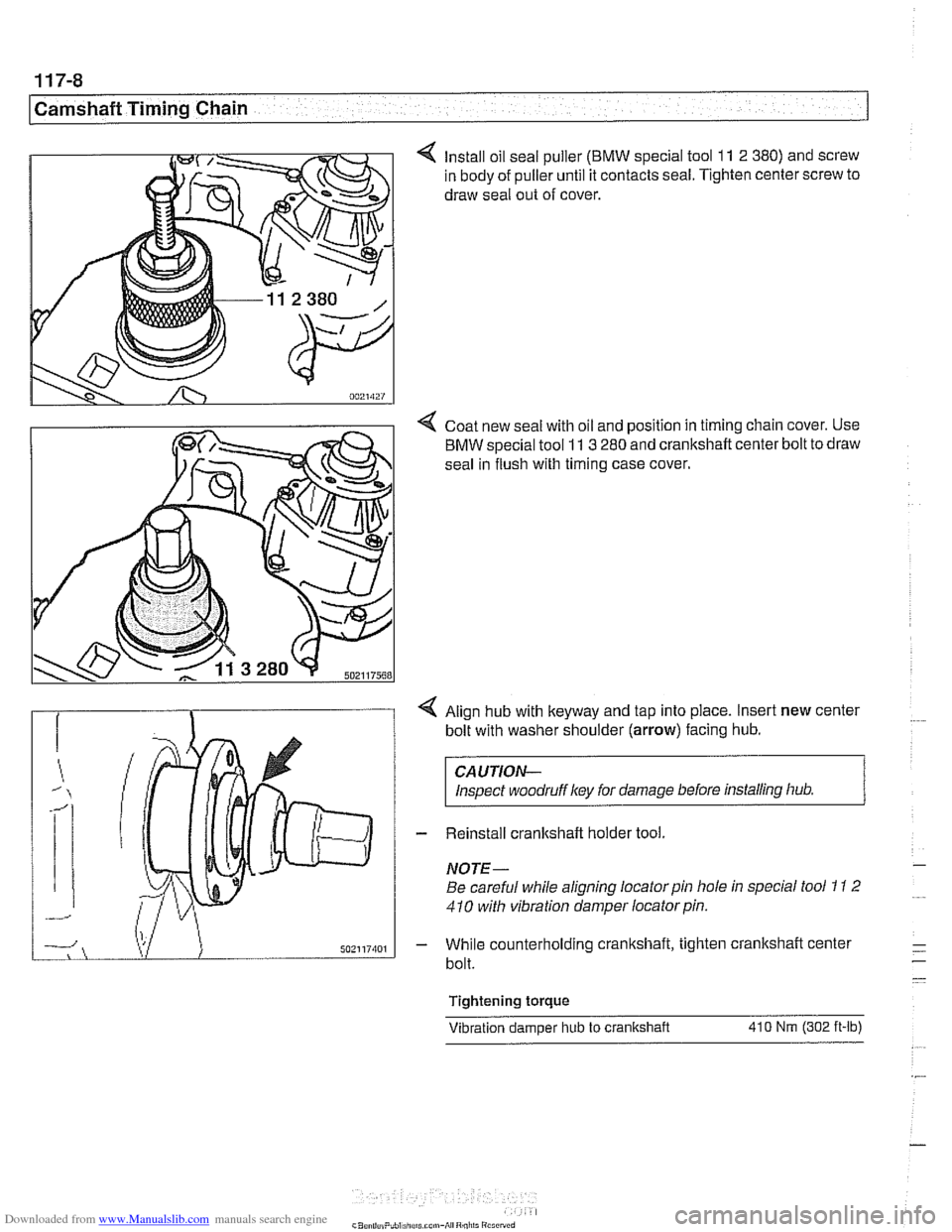
4 Install oil seal puller (BMW special tool 11 2 380) and screw
in body of puller until it contacts seal. Tighten center screw to
draw seal out of cover.
4 Coat new seal with oil and position in timing chain cover. Use
BMW special tool
11 3 280 and crankshaft center bolt to draw
seal in flush with timing case cover.
4 Align hub with keyway and tap into place. Insert new center
bolt with washer shoulder
(arrow) facing hub.
CAUTION-
Inspect woodruffl
NOTE-
Be careful while aligning locator pin hole in special tool 1 I 2
410 with vibration damper locator pin.
- While counterholding cranltshaft, tighten crankshaft center
bolt.
Tightening torque Vibration damoer hub
to crankshaft 410 Nm (302 ft-lb)
Page 247 of 1002
![BMW 525i 1999 E39 Workshop Manual Downloaded from www.Manualslib.com manuals search engine
Camshaft Timing chain]
4 Coat new seal with oil and position in timing chain cover. Use
BMW special tool 11
3 280 and crankshaft center BMW 525i 1999 E39 Workshop Manual Downloaded from www.Manualslib.com manuals search engine
Camshaft Timing chain]
4 Coat new seal with oil and position in timing chain cover. Use
BMW special tool 11
3 280 and crankshaft center](/img/1/2822/w960_2822-246.png)
Downloaded from www.Manualslib.com manuals search engine
Camshaft Timing chain]
4 Coat new seal with oil and position in timing chain cover. Use
BMW special tool 11
3 280 and crankshaft center bolt to draw
seal in flush with timing case cover.
- Align vibration damper assembly with keyway and tap into
place. Insert new center bolt with washer.
CA
UTIOG
Inspect woodruff key for damage before installing hub
assembly.
- Install crankshaft holding tool malting sure tool locks into
place in openings in damper assembly. While counterholding
cranltshaft, tighten crankshaft center bolt.
- Attach special tools 11 8 20011 1 8 190 to damper assembly.
Counterhold damper with 11 8 190 while tightening center
bolt.
Tightening
torque
Vibration damper hub to crankshaft 410 Nm (302 it-ib)
- Installation is reverse of removal noting the following:
Install drive belts. See 020 Maintenance.
Install cooling fan. See 170 Radiator and Cooling Sys-
tem.
Crankshaft oil seal, replacing
(M62 and M62 TU engines)
- Disconnect negative (-) cable from battery
CAUTIOG
Disconnecting the battery may erase fault code(s) storedin
control module memory. Check for fault codes using spe-
cial BMW diagnostic equipment.
* Prior to disconnecting the battery, read the battery dis-
connection cautions in
001 General cautions and
warnings.
- Remove splash guard from beneath engine
- Remove engine cooling fan assembly. See 170 Radiator
and Cooling System.
NOTE
-
Cooling fan nut (32 mm wrench) has left-hand threads.
- Remove drive belts. See 020 Maintenance.
NOTE-
Marlc direction of belt rotation if reusing belt.
Page 268 of 1002
Downloaded from www.Manualslib.com manuals search engine
-- -
Chain 1
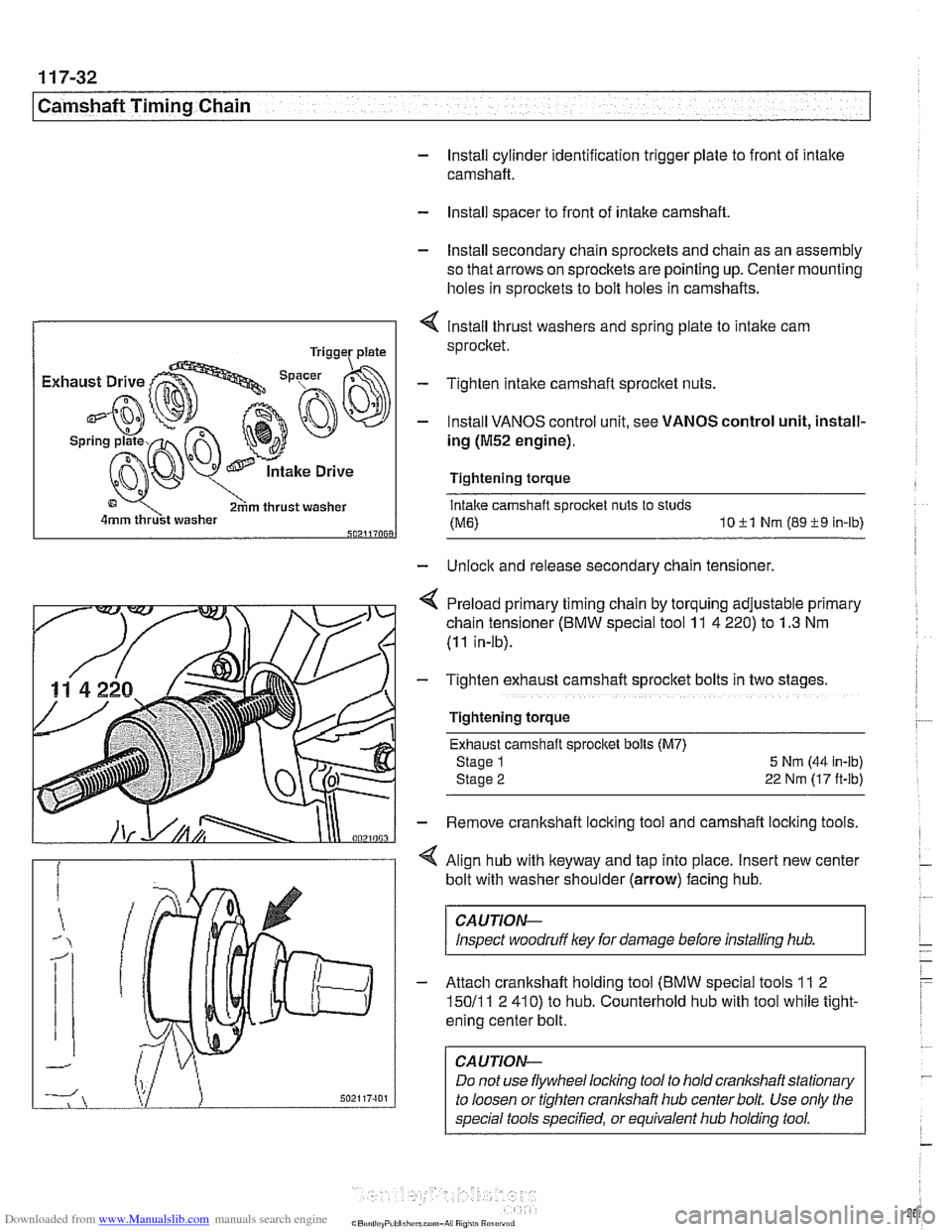
- Install cylinder identification trigger plate to front of intake
camshaft.
- Install spacer to front of intake camshaft
- Install secondary chain sprockets and chain as an assembly
so that arrows on sprockets are pointing up. Center mounting
holes in sprockets to bolt holes in camshafts.
4 lnstall thrust washers and spring plate to intake cam
sprocket.
Tighten intake camshaft sprocket nuts.
- Install VANOS control unit, see VANOS control unit, install-
ing
(M52 engine).
Tightening torque
Intake camshaft sprocket nuts to studs
(ME) 1011 Nm (8919 In-lb) 502117068
- Unlock and release secondary chain tensioner,
4 Preload primary timing chain by torquing adjustable primary
chain tensioner (BMW special tool
11 4 220) to 1.3 Nm
(11 in-lb).
- Tighten exhaust camshaft sprocket bolts in two stage
Tightening torque Exhaust camshaft sprocket bolls (M7)
Stage 1
5 Nrn (44 in-lb)
Stage
2 22 Nm (17 ft-lb)
- Remove crankshaft locking tool and camshaft locking tools.
< Align hub with keyway and tap into place. Insert new center
bolt with washer shoulder (arrow) facing hub.
CAUTION-
Inspect woodruff ley for damage before installing hub.
- Attach crankshaft holding tool (BMW special tools 11 2
15011 1 2 410) to hub. Counterhold hub with tool while tight-
ening center bolt.
CAUTION-
Do not use flywheel locling tool to hold crankshaft stationary
to loosen or tighten
cranlshaft hub center bolt. Use only the
special tools specified, or equivalent hub holding tool.
Page 286 of 1002
Downloaded from www.Manualslib.com manuals search engine
11 7-50
/Camshaft Timing Chain
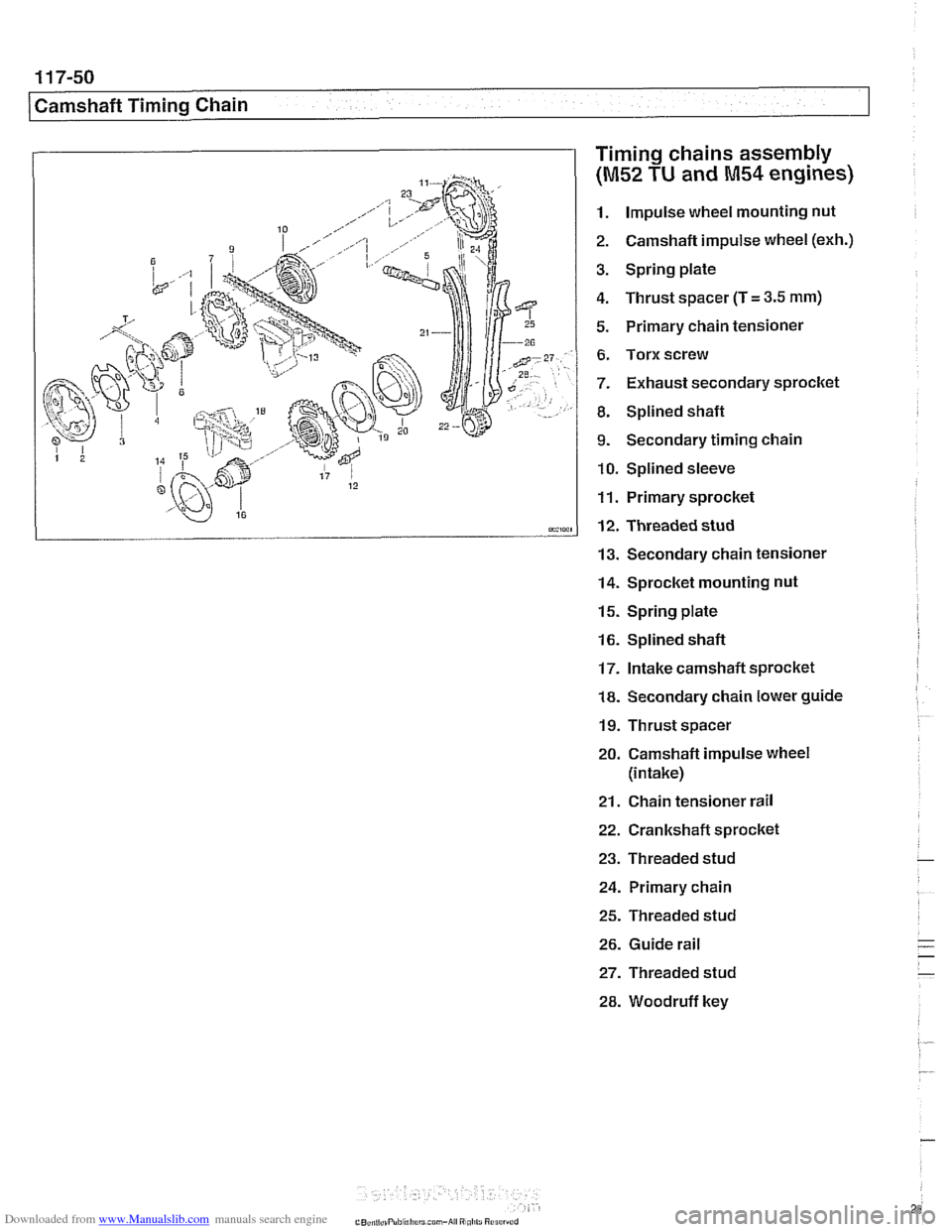
Timing chains assembly
(M52 TU and M54 engines)
1. Impulse wheel mounting nut
2. Camshaft impulse wheel
(exh.)
3. Spring plate
4. Thrust spacer (T
= 3.5 mm)
5. Primary chain tensioner
6. Torx screw
7. Exhaust secondary sprocket
8. Splined shaft
9. Secondary timing chain
10. Splined sleeve
11. Primary sprocket
12. Threaded stud
13. Secondary chain tensioner
14. Sprocket mounting nut
15. Spring plate
16. Splined shaft
17. Intake camshaft sprocket
18. Secondary chain lower guide
19. Thrust spacer
20. Camshaft impulse wheel
(intake)
21. Chain tensioner rail
22. Crankshaft sprocket
23. Threaded stud
24. Primary chain
25. Threaded stud
26. Guide rail
27. Threaded stud
28. Woodruff key
Page 293 of 1002
Downloaded from www.Manualslib.com manuals search engine
... -.
rpp- --- Camshaft Timing Chain1
Timing chains, installing
(M52 TU and M54 engines)
CAUTIOI\C
The procedure outlined below assumes that the camshaits
are lockedin the
TDC installation position with speciallocling
tools as shown earliel:
- inspect timing chain sprockets. Inspect guide rail and ten-
sioner rail for damage. Replace any part that is worn
or dam-
aged.
NOTE-
If any sprockets are being replaced due to wear, the chain
should also be replaced.
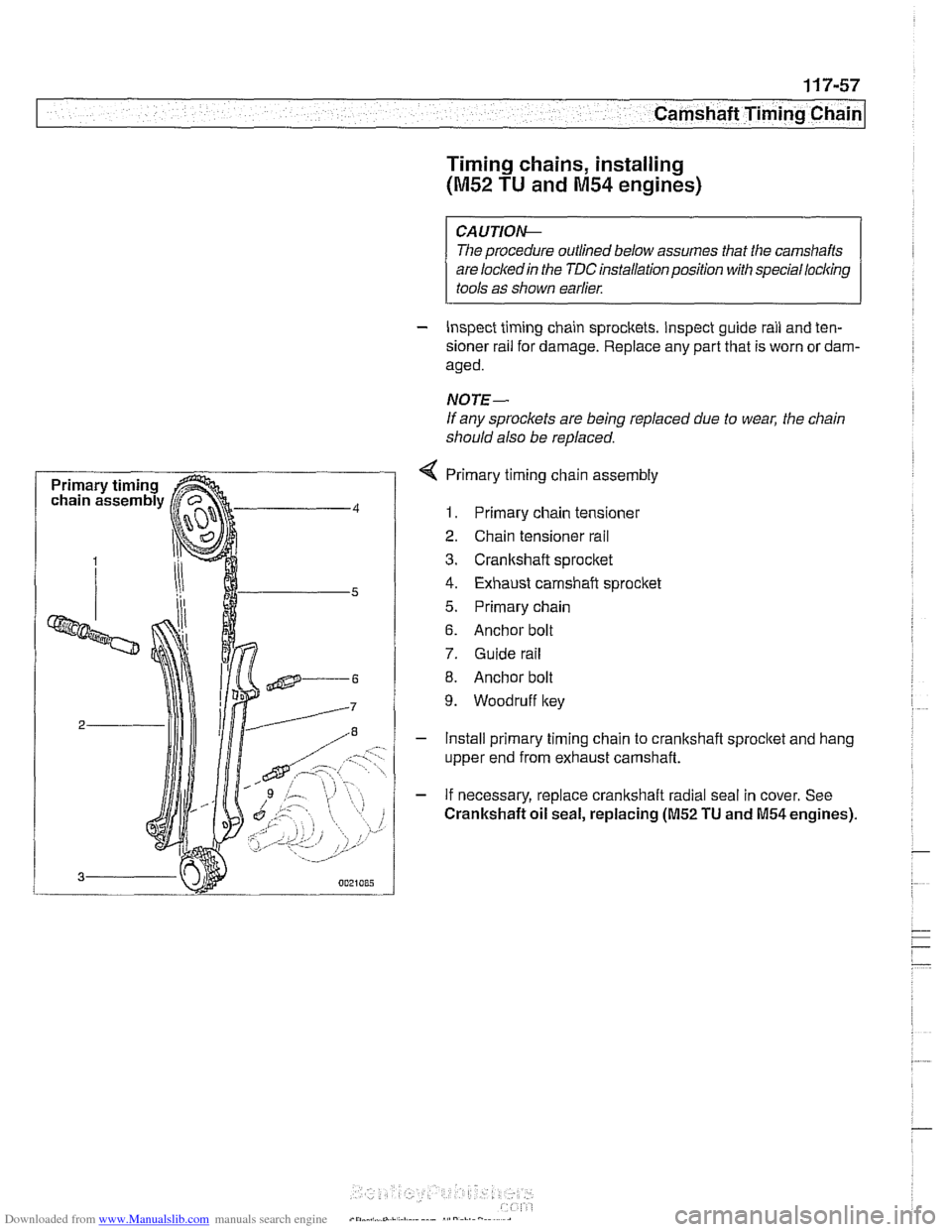
4 Primary timing chain assembly
1. Primary chain tensioner
2. Chain tensioner rail
3. Cranltshaft sprocket
4. Exhaust camshaft sprocket
5. Primary chain
6. Anchor bolt
7. Guide rail
8. Anchor bolt
9. Woodruff key
- Install primary timing chain to crankshaft sprocltet and hang
upper end from exhaust camshaft.
- If necessary, replace crankshaft radial seal in cover. See
Crankshaft oil seal, replacing (M52 TU and M54 engines).
Page 294 of 1002
Downloaded from www.Manualslib.com manuals search engine
(camshaft Timing Chain
- To install lower timing case cover:
- Clean cover and cylinder block sealing surfaces
Use new
gaskets and coolant pipe O-ring.
Remove timing chain cover dowel pins from engine block.
Drive timing cover dowels in until they just protrude slightly
from sealing surface.
Apply a small bead of silicon sealer (Three Bond 1209
63
or equivalent) to corners of cylinder head where timing
cover meets cylinder head and engine block.
Tap cover into position until firmly seated.
lnstall all bolts hand tight, including two Torx bolts from
above.
Install secondary chain lower guide.
Tighten cover mounting bolts alternately and in stages.
Tightening torque
Lower timing cover to cylinder
bloclc (M6) 10 Nrn (89 in-lb)
- Install oil pan with new gasket. See 119 Lubrication Sys-
tem.
Tightening torque
Oil pan
to engine bloclc (M6)
8.8 grade
10.9 grade 10 Nrn (89 in-lb)
12 Nm
(9 ft-lb)
- Align damper assembly with lteyway and tap into place. In-
sert new center bolt with washer.
CAUTION-
Inspect woodruff key for damage before installing hub
assembly.
- Attach special tools 11 8 20011 1 8 190 to damper assembly.
Counterhold damper with
11 8 190 while tightening center
bolt.
CAUTION-
Do not use BMW special tool 1 I 2 300 to hold crankshaft
stationary to tighten cranl(shaft hub center bolt. Use only
the special tools specified, or equivalent hub holding tool.
Have a second person hold special tool
11 8 190 while
tightening center crankshaft bolt.
Tightening torque Crankshaft hub to crankshaft 410 Nrn
(300
ft-lb)
Page 358 of 1002
Downloaded from www.Manualslib.com manuals search engine
.-
ignition System
Disabling ignition system
The ignition system operates in a lethal voltage range and
should be disabled any time engine service or repair work is
being done that requires the ignition to be switched on.
The engine management system can be disabled by remov-
ing the DME main relay. The relay is located in the electronics
box (E-box) in the left rear of the engine
compartment, be.
neath the interior microfilter housing.
CAUTION- Relay locations may
vary. Use care when identifying relays.
See
610 Electrical Component Locations.
Checking for spark
CAUTION-
If
a spark test is done incorrecth damage to the Engine Con-
trol Module
(ECM) or the ignition coils may result.
NOTE-
Spark plug replacement is covered in 020 Maintenance.
Check~ng for spark is d~fflcult on englnes wlth d~str~butorless
ignition systems.
Try removing the spark plugs and inspecting for differences between them.
A poor-firing plug may be wet with fuel and/or ~. - ~
black and sooty, but not always. If a coil is not operating, the
engine management system will electrically disable the fuel
injector to that cylinder. The key is to look for differences be-
tween cylinders.
Ignition coil assembly, testing and
replacing
C4 UTION-
Use a digital multimeter for the following tests. I
- Remove plastic engine cover from top of valve cover by pry-
ing off bolt covers and removing cover mounting bolts.
- Raise car slowly while constantly checking position of jack
and car.
- Disconnect harness connector from coil. Connect multimeter
between terminal 15
(+) in connector and ground.
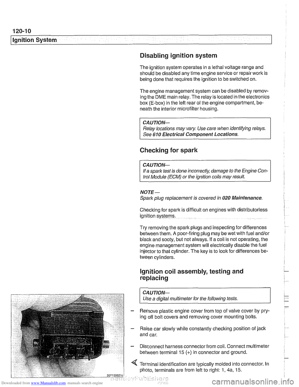
4 Terminal identification are typically molded into connector. In
photo, terminals are from left to right: 1,
4a, 15.
Page 369 of 1002
Downloaded from www.Manualslib.com manuals search engine
Battery, Starter, ~lternatorl
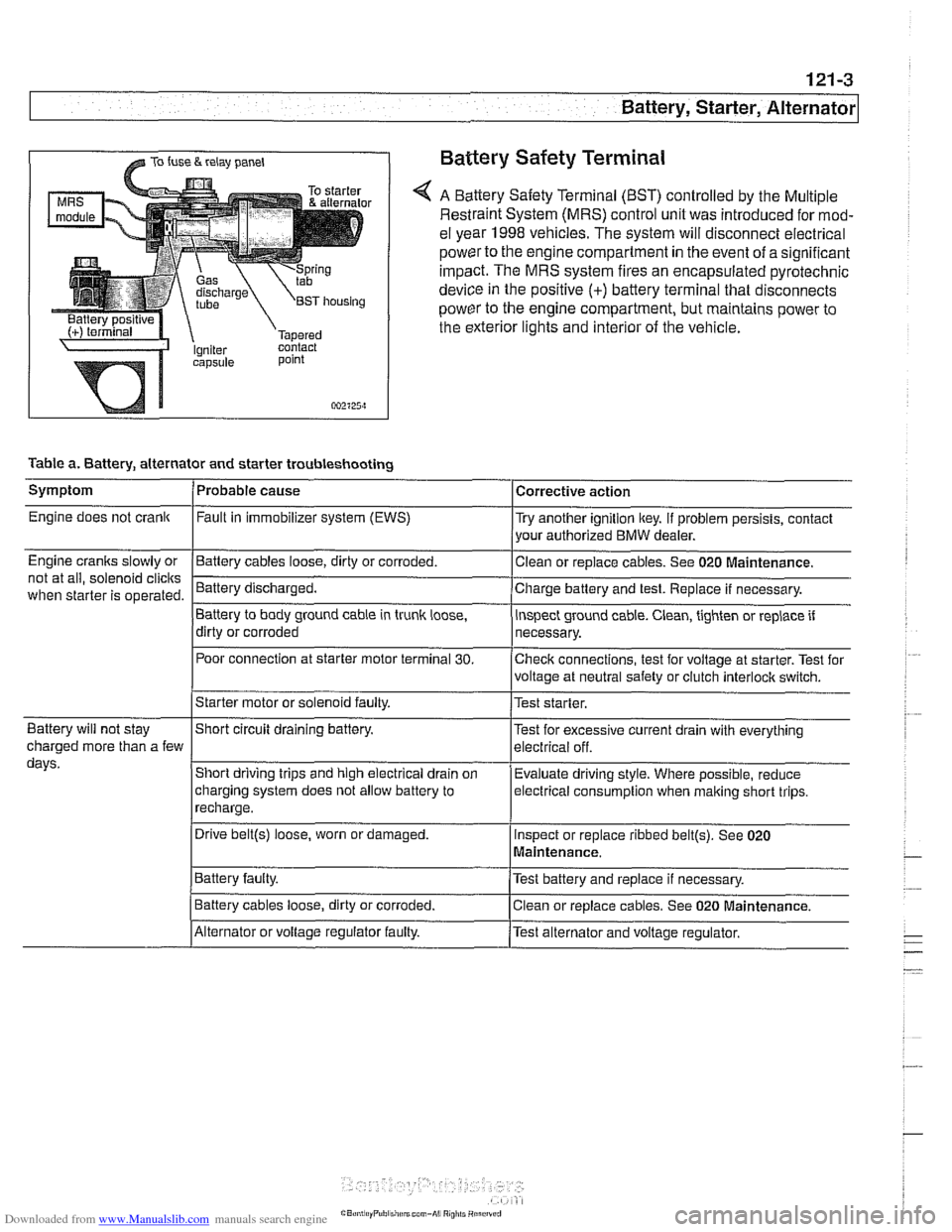
@ TO fuse & relay panel Battery Safety Terminal
A Battery Safety Terminal (BST) controlled by the Multiple
Restraint System (MRS) control unit was introduced for mod-
el year 1998
vehicles. The system will disconnect electrical
power to the engine compartment
in the event of a significant
impact. The MRS system fires an encapsulated pyrotechnic
device
in the positive (+) battery terminal that disconnects
power to the engine compartment, but maintains power to
the exterior lights and interior of the vehicle.
point
002125~1
Table a. Battery, alternator and starter troubleshooting
1-
/Starter motor or solenoid faulty. l~est starter.
Symptom
Engine does not crank
Engine cranks slowly or
not at all, solenoid
clicits
when starter is operated.
I I
Battery will not stay IShort circuit draining battery. l~est for excessive current drain with everything
Probable cause
Fault
in immobilizer system (EWS)
-Clean Battery cables loose, dirty or corroded.
Battery discharged.
Battery to body ground cable in trunk
loose,
dirty or corroded
Poor connection at starter motor terminal
30.
Corrective action
Try another ignition key. If problem persists, contact
your authorized BMW dealer.
or replace cables. See 020
~aintenance.
Charge battery and test. Replace if necessary.
inspect ground cable. Clean, tighten or replace if
necessary.
Checlc connections, test for voltage at starter. Test for
voltage at neutral safety or clutch
interloclc switch.
charged more than a few
days.
I~atter~ faulty. /Test battery and replace if necessary.
Short driving trips and high electrical drain
on
charging system does not allow battery to
recharge.
. I
I Battery cables loose, dirty or corroded. Iclean or replace cables. See 020 Maintenance.
Evaluate driving
style. Where possible, reduce
electrical
consumption when malting short trips.
Drive
belt@) loose, worn or damaged.
IAlternator or voltage regulator faulty. /Test alternator and voltage regulator.
Inspect
or replace ribbed
belt@). See 020
Maintenance.