sensor BMW 525i 2000 E39 Owner's Guide
[x] Cancel search | Manufacturer: BMW, Model Year: 2000, Model line: 525i, Model: BMW 525i 2000 E39Pages: 1002
Page 169 of 1002
Downloaded from www.Manualslib.com manuals search engine
1 13-75
Cylinder Head Removal and Installation I
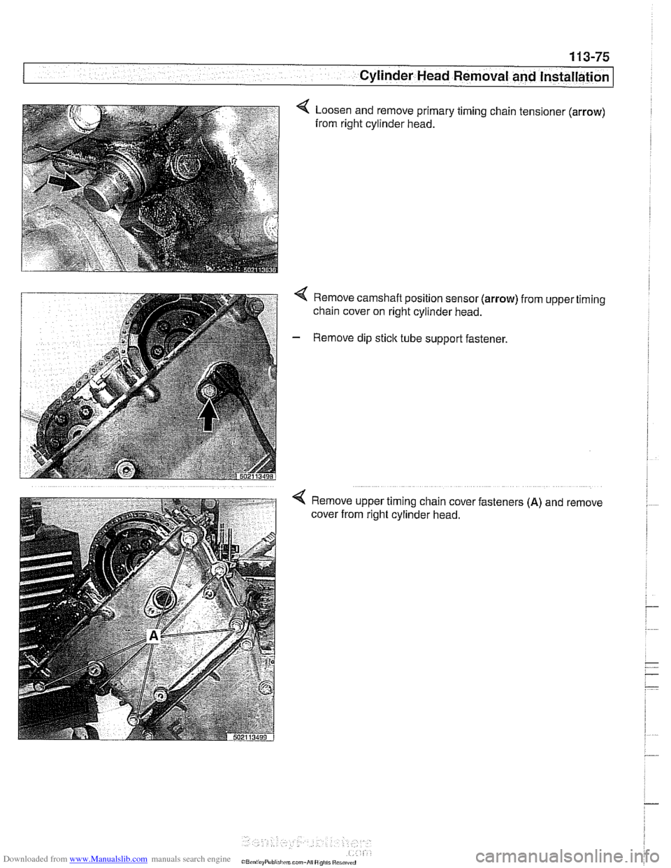
4 Loosen and remove primary timing chain tensioner (arrow)
from right cylinder head.
Remove camshaft position sensor (arrow)
chain cover on right cylinder head.
Remove dip
stick tube support fastener. from
upper
Remove upper timing chain cover fasteners
(A) and
cover from right cylinder head. timing
remove
Page 173 of 1002
Downloaded from www.Manualslib.com manuals search engine
-8" ."
Cylinder Head Removal and Installation --
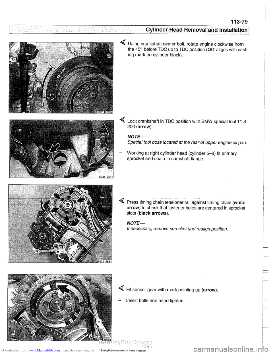
Using crankshaft center bolt, rotate engine clockwise from
the
45" before TDC up to TDC position (OIT aligns with cast-
ing mark on cylinder block).
< Lock crankshaft in TDC position with BMW special tool 11 3
200 (arrow).
NOTE-
Special tool boss located at the rear of upper engine oil pan.
- Working at right cylinder head (cylinder 5-8) fit primary
sprocltet and chain to camshaft flange.
!
I
4 Press timing chain tensioner rail against timing chain (white
arrow) to check that fastener holes are centered in sprocket
slots (black arrows).
NOTE-
If necessary, remove sprocl
Insert bolts and hand tighten.
Page 190 of 1002
Downloaded from www.Manualslib.com manuals search engine
116-14
I Cylinder Head and Valvetrain
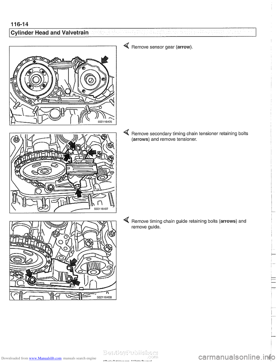
4 Remove sensor gear (arrow).
Remove secondary timing chain tensioner retaining bolts
(arrows) and remove tensioner.
Remove timing chain guide
reta~ning bolts (arrows) and
remove guide.
Page 213 of 1002
![BMW 525i 2000 E39 Owners Guide Downloaded from www.Manualslib.com manuals search engine
-
. - - -- Cylinder Head and valvetrain]
Turn engine over twice in direction of rotation until cylinder 1
intake and exhaust camshaft BMW 525i 2000 E39 Owners Guide Downloaded from www.Manualslib.com manuals search engine
-
. - - -- Cylinder Head and valvetrain]
Turn engine over twice in direction of rotation until cylinder 1
intake and exhaust camshaft](/img/1/2822/w960_2822-212.png)
Downloaded from www.Manualslib.com manuals search engine
-
. - - -- Cylinder Head and valvetrain]
Turn engine over twice in direction of rotation until cylinder 1
intake and exhaust camshaft lobes (arrows) face each other.
- Lock crankshaft in TDC position with BMW special tool
11 2 300.
4 Place BMW special tool set 11 3 240 over camshafts and
measure clearances.
NOTE-
@ If the exhaust side of the tool (A) is not flush with the head,
camshaft timing is incorrect. Reset camshaft timing as de-
scribed in 11
7 Camshaft Timing Chain.
Due to flexible sprocket design, VANOS unit tolerances
and play in the VANOS splines, when the camshaft timing
is set correctly, the intake side of special tool set
11 3 240
(B) may be up to 1 mm (0.04 in.) above the suiface of the
cylinder head. This is normal. Reassemble engine. Other-
wise, reset camshaft timing as describedin 1
l?Camshaft
Timing Chain.
- Remove BMW special tool 11 6 150 from front of cylinder
head.
4 Clean contact edges of cylinder head face and VANOS unit
and apply a thin coat of Three Bond
12090 or equivalent
sealing compound to surfaces.
CAUTION-
Male sure all gasket material is removed from face of cyl-
inder head. Clean sealing face and keep free of oil.
Check locating dowel
(A) and dowel sleeve (B) at top
of cylinder head for damage or incorrect installation.
- Using a new steel gasket, install VANOS unit to front of cyi-
inder head. See 117 Camshaft Timing Chain.
NOTE-
If VANOS control unit is being replaced, be sure to check and
adjust camshaft timing as described in 117 Camshaft Tim-
ing Chain.
- Reinstall engine lifting eye.
- Reconnect electrical harness connectors to camshaft posi-
tion sensors and
VANOS solenoid valves.
Page 216 of 1002
Downloaded from www.Manualslib.com manuals search engine
-. .
Cylinder Head and Valvetrain -- v . -- --- --
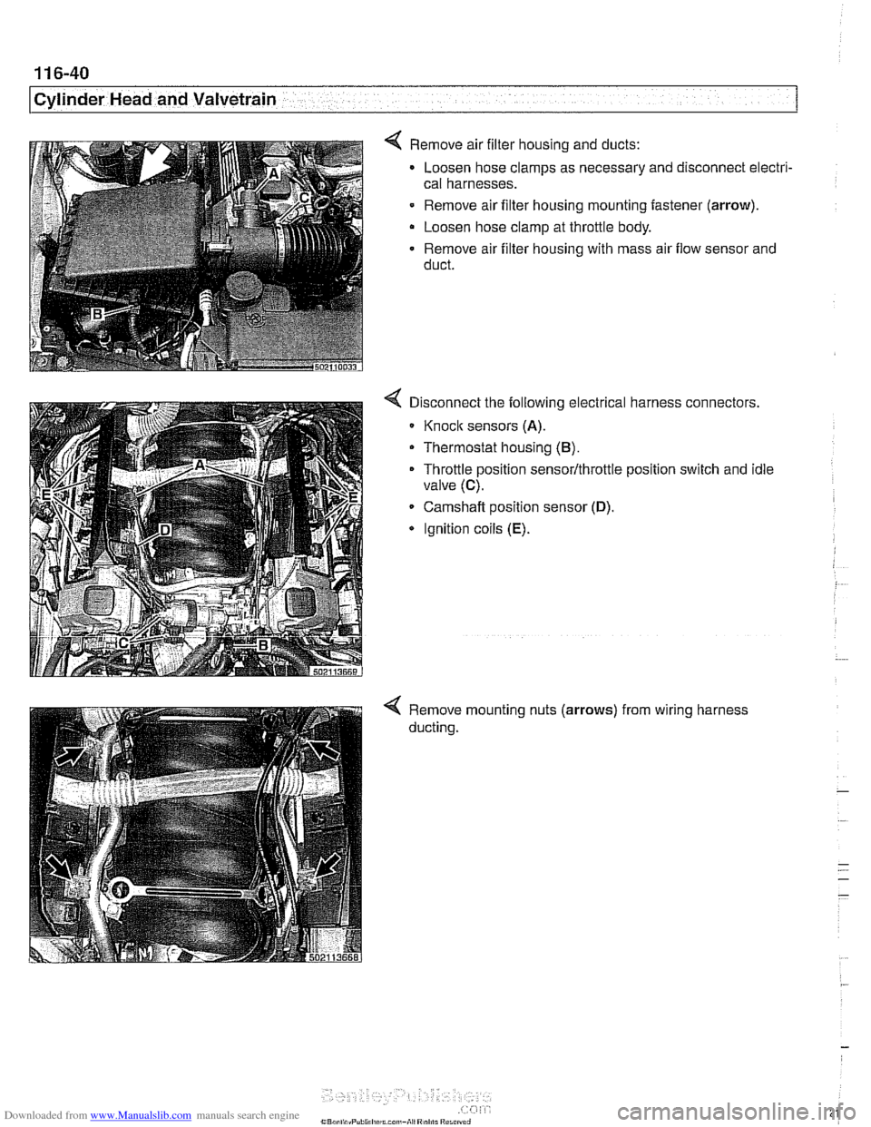
4 Remove air filter housing and ducts:
Loosen hose clamps as necessary and disconnect electri-
cal harnesses.
- Remove air filter housing mounting fastener (arrow).
Loosen hose clamp at throttle body.
Remove air filter housing with mass air flow sensor and
duct.
Disconnect the following electrical harness connectors.
Knoclc sensors (A).
Thermostat housing (B).
Throttle position sensor/throttle position switch and idle
valve
(C).
Camshaft position sensor (D).
* Ignition coils (E).
Remove mounting nuts (arrows)
ducting. from
wiring harness
Page 219 of 1002
Downloaded from www.Manualslib.com manuals search engine
Cylinder Head and valvetrain1
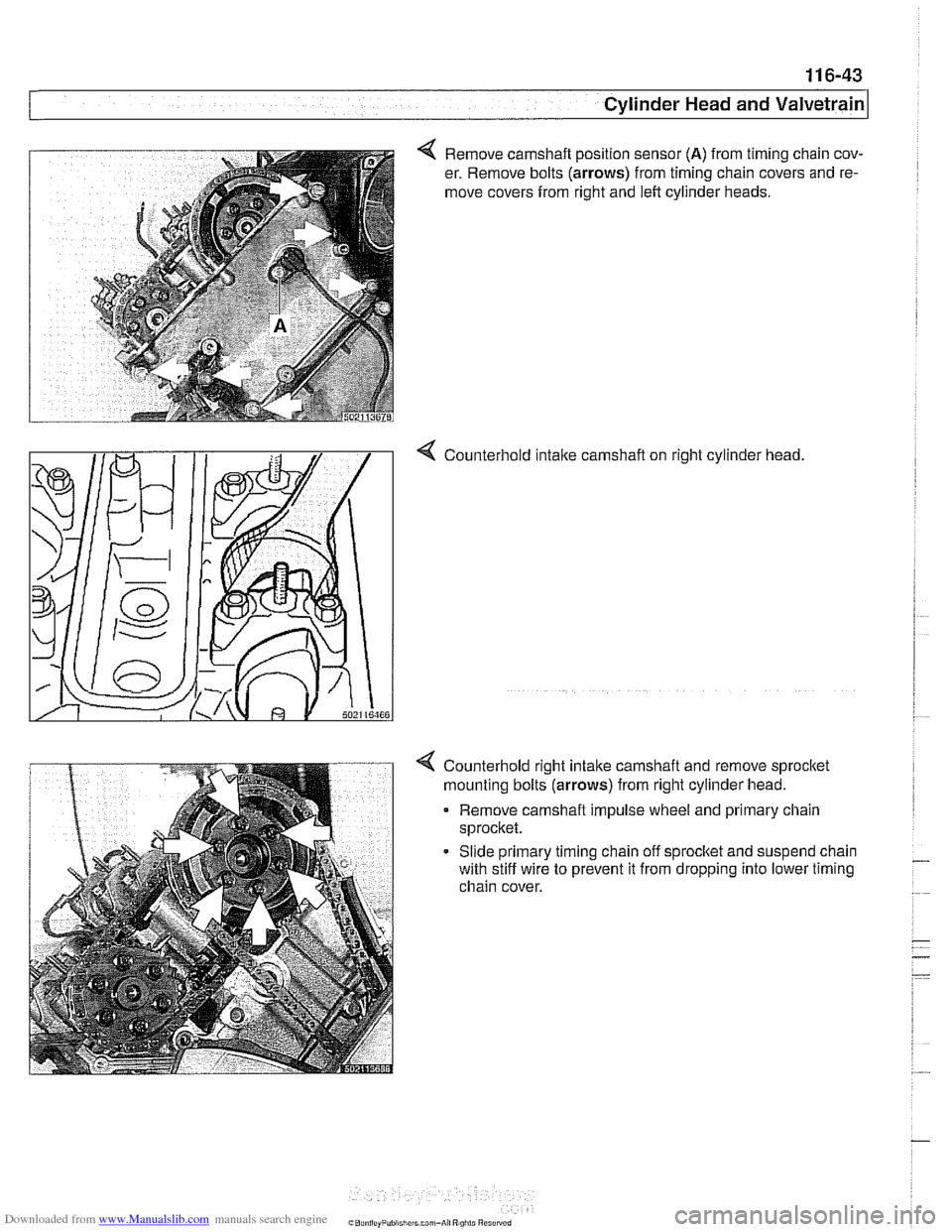
4 Remove camshaft position sensor (A) from timing chain cov-
er. Remove bolts
(arrows) from timing chain covers and re-
move covers from right and left cylinder heads.
4 Counterhold intalte carnshaft on right cylinder head
4 Counterhold right intalte camshaft and remove sprocltet
mounting bolts
(arrows) from right cylinder head.
Remove carnshaft impulse wheel and primary chain
sprocket.
- Slide primary timing chain off sprocltet and suspend chain
with stiff wire to prevent it from dropping into lower timing
chain cover.
Page 229 of 1002
Downloaded from www.Manualslib.com manuals search engine
Cylinder Head and valvetrain'
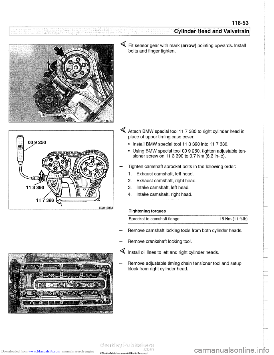
Fit sensor gear with mark (arrow) pointing upwards. Install
bolts and finger tighten.
4 Attach BMW special tool 11 7 380 to right cylinder head in
place of upper timing case cover.
Install BMW special tool
11 3 390 into 11 7 380.
Using BMW special tool 00 9 250, tighten adjustable ten-
sioner screw on
11 3 390 to 0.7 Nm (6.3 in-lb).
- T~ghten camshaft sprocket bolts in the following order:
1. Exhaust camshaft, left head.
2. Exhaust camshaft, right head.
3. Intake camshaft, left head.
4. Intake camshaft, right head.
Tightening torques Sprocket
to camshaft flange 15 Nm (I 1 ft-lb)
- Remove camshaft locking tools from both cylinder heads.
- Remove crankshaft locking tool.
4 lnstall oil lines to left and right cylinder heads.
- Remove adjustable timing chain tensioner tool and setup
block from right cylinder head.
Page 260 of 1002
Downloaded from www.Manualslib.com manuals search engine
1 17-24
I Camshaft Timing Chain
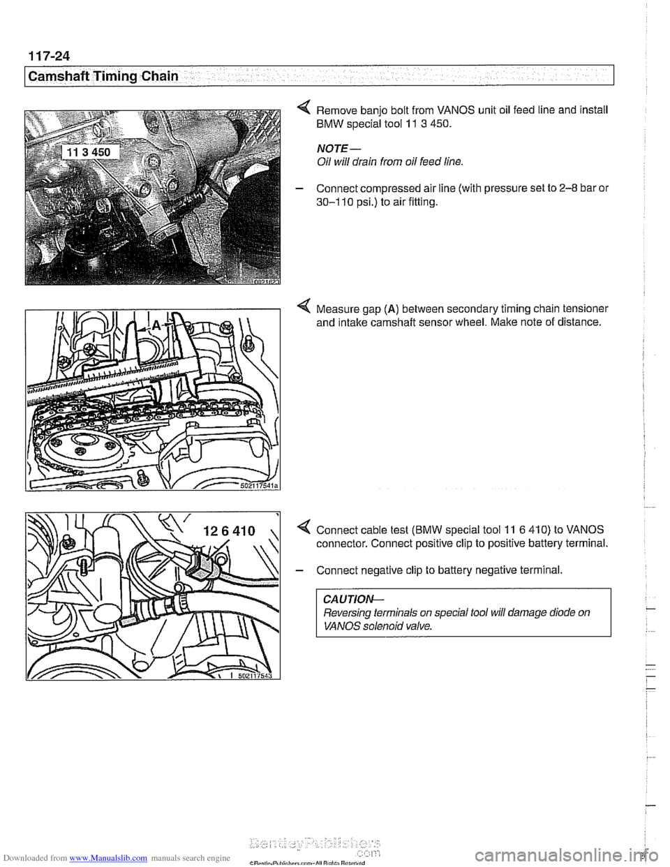
4 Remove banjo bolt from VANOS unit oil feed line and install
BMW special tool 11 3 450.
NOTE-
Oil will drain from oil feed line.
- Connect compressed air line (with pressure set to 2-8 bar or
30-1 10 psi.) to air fitting.
4 Measure gap (A) between secondary timing chain tensioner
and
intake camshaft sensor wheel. Make note of distance.
4 Connect cable test (BMW special tool 11 6 410) to VANOS
connector. Connect positive clip to positive battery terminal.
- Connect negative clip to battery negative terminal.
CAUTION-
Reversing terminals on special tool will damage diode on
VANOS solenoid valve.
Page 261 of 1002
Downloaded from www.Manualslib.com manuals search engine
-
Camshaft Timing Chain -. -
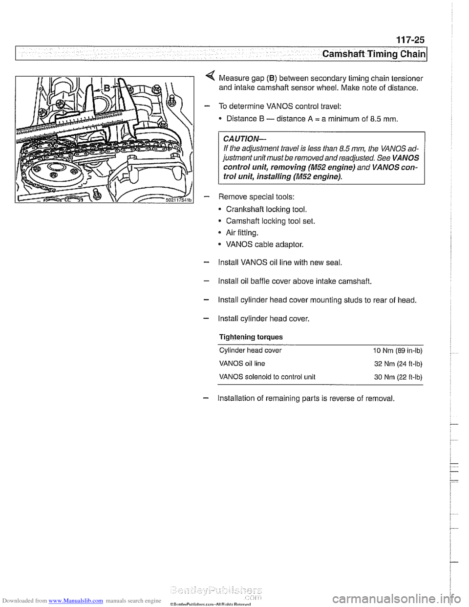
Measure gap (B) between secondary timing chain tensioner
and intake camshaft sensor wheel. Make note of distance.
To determine VANOS control travel:
Distance
I3 - distance A = a minimum of 8.5 mm
CAUTION-
If the adjustment travel is less than 8.5 mm the VANOS ad-
justment unit must be removed and readjusted. See
VANOS
control unit, removing (M52 engine)
and VANOS con-
trol unit, installing
(M52 engine).
Remove special tools:
Cranltshaft locking tool.
Camshaft
loclting tool set.
Air fitting.
* VANOS cable adaptor.
- Install VANOS oil line with new seal
- Install oil baffle cover above intake camshaft.
- Install cylinder head cover mounting studs to rear of head.
- Install cylinder head cover,
Tightening
torques
Cylinder head cover 10 Nrn (89 in-lb)
VANOS oil line
32 Nm (24 R-lb)
VANOS solenoid to control unit 30 Nrn (22 ft-lb)
- Installation of remaining parts is reverse of removal.
Page 262 of 1002
Downloaded from www.Manualslib.com manuals search engine
Camshaft Timing Chain Timing chains, removing
(M52 engine)
Camshaft timing chain removal on M52 engines requires en-
gine oil pan removal.
Special
BMW sewice tools are needed for timing chain re-
moval and installation procedures. The special tools assure
propertiming of thevalvetrain. Precise marks to
setthe timing
on the camshafts are not provided for reassembly. Read the
procedures through before beginning the job.
NOTE-
If the camshafts are not properly timed, the pistons can con-
tact the valves.
- Remove VANOS control unit. See VANOS control unit, re-
moving (M52 engine).
- Remove radiator cooling fan and shroud. See 170 Radiator
and Cooling System.
- Drain cooling system. See 170 Radiator and Cooling Sys-
tem.
- Remove coolant hoses from thermostat housing and remove
thermostat housing from front of cylinder head.
- Loosen bolts for coolant pump pulley.
- Remove drive belts for alternator and AIC compressor. See
020 Maintenance.
- Remove coolant pump pulley.
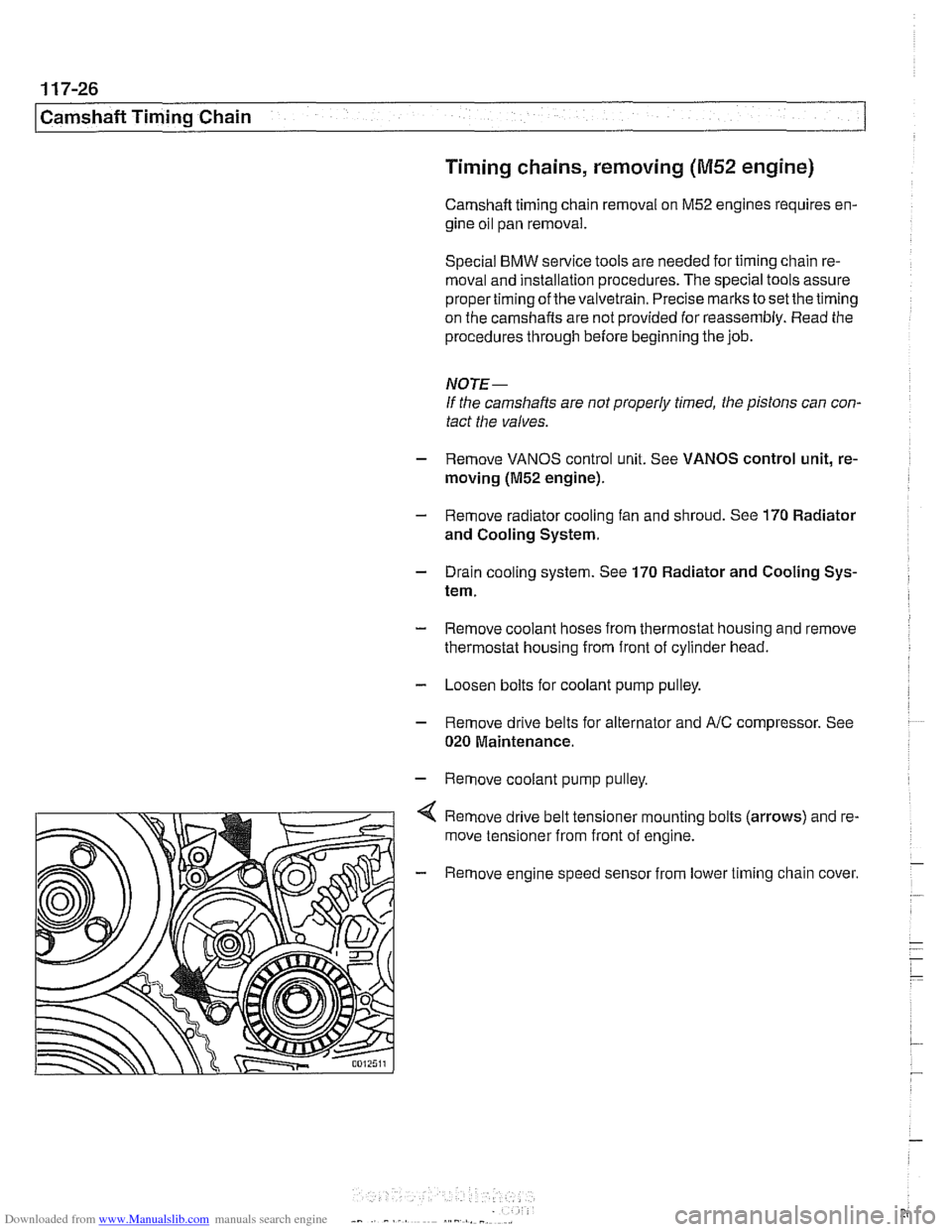
Remove drive belt tensioner mounting bolts (arrows) and re-
move tensioner from front of engine.
- Remove engine speed sensor from lower timing chain cover.