Suspension BMW 525i 2001 E39 Workshop Manual
[x] Cancel search | Manufacturer: BMW, Model Year: 2001, Model line: 525i, Model: BMW 525i 2001 E39Pages: 1002
Page 3 of 1002
Downloaded from www.Manualslib.com manuals search engine
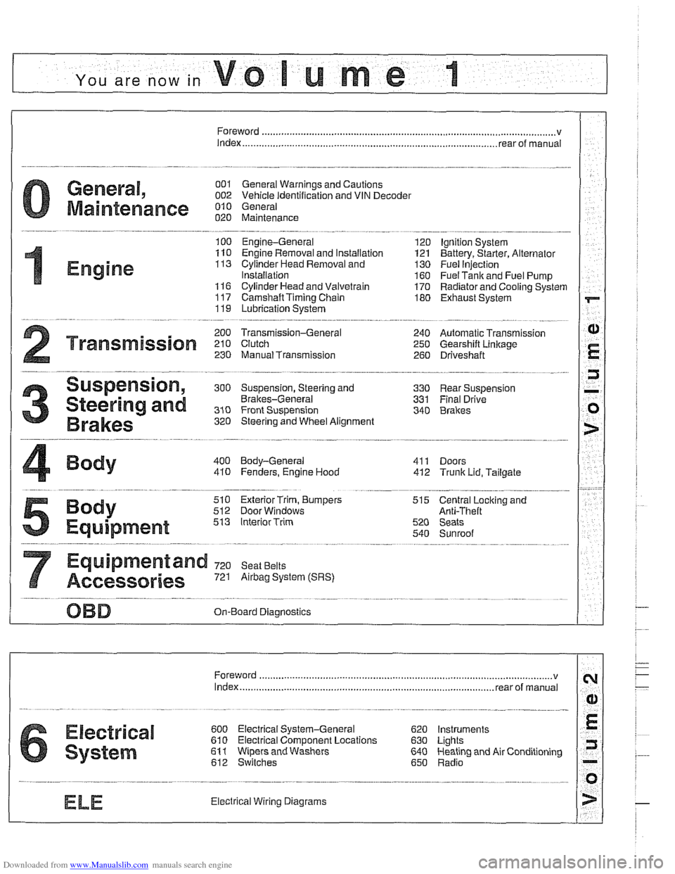
YOU are now in Volume I
I
Foreword ................... .. ........................................................................\
.......... v
Index
........................ .. ................................................................ rear of manual
General, 001 General Warnings and Cautions 002 Vehicle Identification and VIN Decoder
Maintenance OiO 020 Maintenance
Engine
100 Engine-General 110 Engine Removal and Installation
113 Cylinder Head Removal and
Installation
116 Cyiinder Head and Valvetrain 117 Camshaft Timing Chain
119 Lubrication System
200 Transmission-General
2 Transmission 210 clutch 230 ManualTransmission
I20 Ignition System
121 Battery, Starter, Alternator
130 Fuel Injection
160 Fuel Tank and Fuel Pump 170 Radiator and Cooling System
180 Exhaust System
240 Automatic Transmission
250 Gearshift Linkage 260 Driveshaft
Suspension, 300 Suspension, Steering and 330 Rear Suspension
Brakes-General 331 Final Drive
Steering and No Front Suspension 340 Brakes
320 Steering and Wheel Alignment
400 Body-General
410 Fenders, Engine Hood 411 Doors
412 Trunk Lid, Tailgate
510 Exterior Trim, Bumpers 512 Door Windows
Equipment 513 Interior Trim
7
Equipment and 720 seat Belts
Accessories 721 Airbag System (SRS)
OBD On-Board Diagnostics
. ............ ..
515 Central Lociting and
Anti-Theft
520 Seats 540 Sunroof
.................................................................... Foreword .............................. .. v
Index ................... .. ................................................................ rear of manual
Electrical
6 system
600 Electrical System-General 620 Instruments
610 Electrical Comoonent Locations 630 Liohts
611 wipers and washers 612 Switches eati in^ and Air Conditioning
Radio
. ........... ........ .........................
Electrical Wiring Diagrams
Page 12 of 1002
Downloaded from www.Manualslib.com manuals search engine
01 0-2
General
This section is intended to help the do-it-yourselfer get start-
ed. Tips on workshop practices, basic tools, and a quick refer-
ence guide to emergencies can be found here.
WARNING-
Do not use this manual unless you are familiar with basic
automotive repair procedures and safe workshop
practices.
0 This manual illustrates the worl
and up-to-date information from the vehicle manufac-
turer or for proper training as an automotive technician.
Note that it is not possible to anticipate all of the ways
or conditions under which vehicles may be serviced or
to provide cautions as to all of the possible hazards that
may result.
MOW TO USE THIS MANUAL
WARNING -
Your common sense and goodjudgement are crucial to safe
and successful service
work. Read procedures through be-
fore starting them. Think about whether the condition of your
cac your level of mechanical skill, or pour level of reading
comprehension might result in or contribute in some way to
an occurrence that might cause you injury, damage your car;
or result in an unsafe repair. If you have doubts for these or
other reasons about your ability to perform safe repair work
on your car; have the work done at an authorized
BMW deal-
er or other qualified shop.
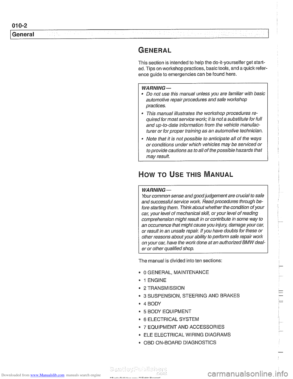
The manual is divided into ten sections:
0 GENERAL, MAINTENANCE
0 I ENGINE
2 TRANSMISSION
3 SUSPENSION, STEERING AND BRAKES
4 BODY
5 BODY EQUIPMENT
6 ELECTRICAL SYSTEM
7 EQUIPMENT AND ACCESSORIES
- ELE ELECTRICAL WIRING DIAGRAMS
OBD ON-BOARD DIAGNOSTICS
Page 33 of 1002
Downloaded from www.Manualslib.com manuals search engine
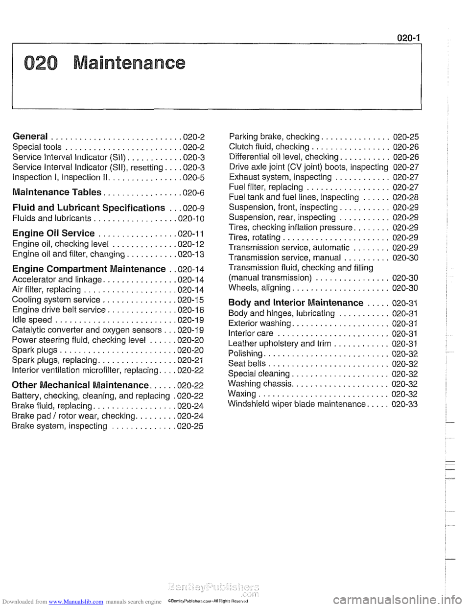
020 Maintenance
General ........................... .02 0.2
Special tools ........................ .02 0.2
Service Interval Indicator (Sll) ........... .02 0.3
Service Interval Indicator (Sll), resetting ... .02 0.3
Inspection I, Inspection 11 ............... .02 0.5
Maintenance Tables ................ .02 0.6
Fluid and Lubricant Specifications .. .02 0.9
Fluids and lubricants ................. .02 0.10
Engine Oil Service ................ .02 0.1 I
Engine oil. checking level ............. .02 0.12
Engine oil and filter. changing .......... .02 0-13
Engine Compartment Maintenance . .02 0.14
Accelerator and linkage ............... .02 0.14
Air filter. replacing ................... .02 0.1 4
Cooling system service ............... .02 0.15
Engine drive belt service .............. .02 0.16
Idlespeed .......................... 020-19
Catalytic converter and oxygen sensors .. .02 0.19
Power steering fluid, checking level ..... .02 0.20
Spark plugs ........................ .02 0.20
Spark plugs, replacing ................ .02 0.21
Interior ventilation microfilter, replacing ... .02 0.22
Other Mechanical Maintenance ..... .02 0.22
Battery, checking. cleaning. and replacing .02 0-22
Brake fluid. replacing ................. .02 0-24
Brake pad 1 rotor wear. checking ........ .02 0.24
Brake system, inspecting ............. .02 0.25
Parking brake. checking ............... 020-25
Clutch fluid. checking ................. 020-26
Differential oil level. checking ........... 020-26
Drive axle joint (CV joint) boots. inspecting 020-27
Exhaust system. inspecting ............ 020-27
Fuel filter. replacing .................. 020-27
Fuel tank and fuel lines. inspecting ...... 020-28
Suspension. front. inspecting ........... 020-29
Suspension. rear. inspecting ........... 020-29
Tires. checking inflation pressure ........ 020-29
Tires. rotating ....................... 020-29
Transmission service. automatic ........ 020-29
Transmission service. manual .......... 020-30
Transmission fluid. checking and filling
(manual transmission)
................ 020-30
Wheels. aligning ..................... 020-30
Body and Interior Maintenance ..... 020-31
Body and hinges. lubricating ........... 020-31
Exterior washing ..................... 020-31
Interior care ........................ 020-31
Leather upholstery and trim ............ 020-31
Polishing ........................... 020-32
Seat belts .......................... 020-32
Special cleaning ..................... 020-32
Washing chassis ..................... 020-32
Waxing ............................ 020-32
Windshield wiper blade maintenance ..... 020-33
Page 61 of 1002
Downloaded from www.Manualslib.com manuals search engine
Maintenance
Suspension, front, inspecting
Inspection of the front suspension and steering includes a
check of all moving parts
forwear and excessive play. Inspect
ball joint and tie-rod rubber seals and boots for cracks
ortears
that could allow the entry of dirt, water, and other
contaminants. See
310 Front Suspension.
Suspension, rear, inspecting
Differential and rear drive axle service consists of checking
and changing the gear oil, inspecting for leaks, and checking
the drive axle
CV joint boots for damage.
The areas where
lealts are most likely to occurare around the
drive shaft and drive axle mounting flanges. For more infor-
mation on identifying oil leaks and theircauses, see
330 Rear
Suspension and
331 Final Drive.
Tires, checking inflation pressure
Correct tire pressures are important to handling and stability,
fuel economy, and tire wear. Tire pressures change with tem-
perature. Pressures should be
checked oRen during season-
al temperature changes. Correct inflation pressures can be
found on the driver's door pillar and in the owner's manual.
Note that tire pressures should be higher when the car is
more heavily loaded.
WARNING-
Do not inflate any tire to a pressure higher than the tire's max-
imum inflation pressure listedon the sidewall. Use care when
adding air to warm tires. Warm tire pressures can increase as
much as
4 psi (0.3 bar) over their coldpressures.
Tires, rotating
BMW does not recommend tire rotation. Due to the car's sus-
pension design, the front tires begin to wear first at the outer
shoulder and the reartires begin to wearfirst at the middle of
the tread or inner shoulder. Rotating the tires may adversely
affect road handling and tire grip.
Transmission service, automatic
The automatic transmissions installed in E39 models are
filled with special automatic transmission fluid. The transmis-
sion lubricant type can be found on the "type-plate" on the
side of the transmission. The recommended lubricants are
listed earlier in this repair group. See Fluids and lubricants.
If in doubt, consult an authorized BMW dealer for alternate
Page 91 of 1002
Downloaded from www.Manualslib.com manuals search engine
110-19
Engine Removal and Installation
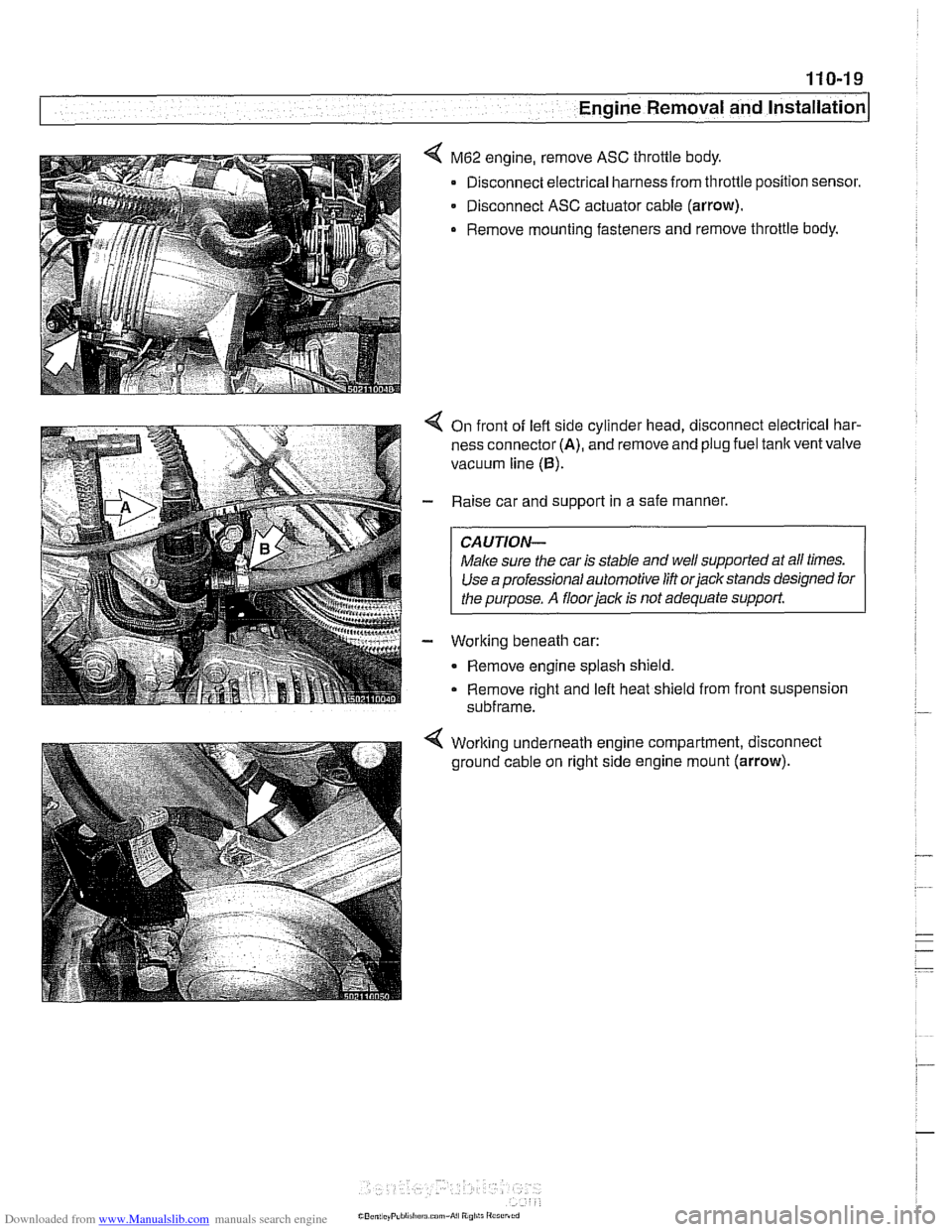
M62 engine, remove ASC throttle body.
Disconnect electrical harness from throttle position sensor.
- Disconnect ASC actuator cable (arrow).
. Remove mounting fasteners and remove throttle body.
On front of left side cylinder head, disconnect electrical har-
ness connector
(A), and remove and plug fuel tank vent valve
vacuum line
(0).
Raise car and support in a safe manner.
CAUTION-
Male sure the car is stable and well supported at aN times.
Use a professional automotive
lifi orjackstands designed for
I the ouroose. A floor jack is not adequate support.
Working beneath car:
- Remove engine splash shield.
Remove right and left heat shield from front suspension
subframe.
Working underneath engine compartment, disconnect
ground cable on right side engine mount
(arrow).
Page 322 of 1002
Downloaded from www.Manualslib.com manuals search engine
11 9-2
Lubrication System
This repair group covers lubrication system troubleshooting
as well as oil pan removal and oil pump replacement.
In 6-cylinder models, removal of the oil pan requires the re-
moval of the exhaust system and some front suspension
components. Those procedures are fully covered in:
180 Exhaust System
210 Clutch
230 Manual Transmission
0 240 Automatic Transmission
310 Front Suspension
320 Steering and Wheel Alignment
NOTE-
Oil change procedure and oil filter replacement are covered
in
020 Maintenance.
CAUTIOG
V8 engines: The oil pump fasteners (including the sprocket
retaining nut) are known to vibrate loose. This can result in oil
starvation and engine failure. Be sure to check oil bolts and
nut tightness whenever the
oilpump is accessible. If any fas-
teners are found to be loose, remove them and reinstall with
Loctite
Band torque to specifications.
Special tools
The engine needs to be properly supported while the front
suspension
subframe is lowered to access the oil pan.
A standard oil pressure gauge may be used for measuring oil
pressure.
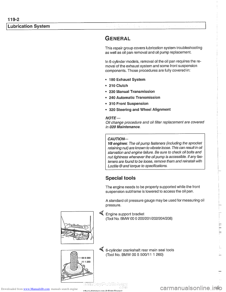
Engine support bracket
(Tool No, BMW 00 0 20012011202~2041208)
4 6-cylinder crankshalt rear main seal tools
(Tool No. BMW 00 5 50011
1 1 260)
Page 330 of 1002
Downloaded from www.Manualslib.com manuals search engine
11 9-1 0
Lubrication System
Oil pan, removing and installing
(6-cylinder)
The engine oil pan removal procedure requires that the en-
gine be supported from the top and the front suspension
sub-
frame be lowered.
- Raise car and place securely on jack stands.
Make sure the car is stable and well supported at all times.
Use a professional automotive
lift orjackstands designed for
- Remove splash shield from under engine.
- Drain engine oil as described in 020 Maintenance.
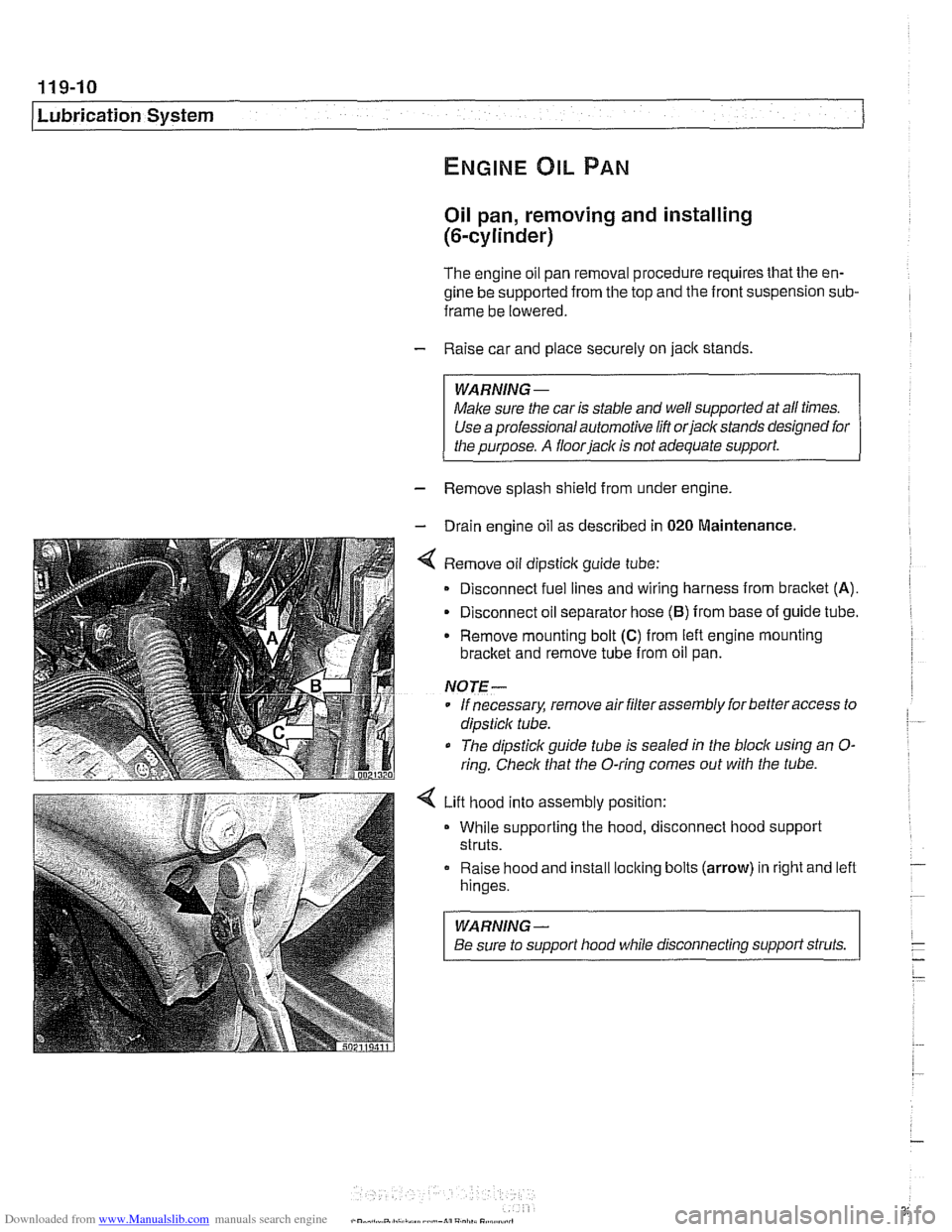
4 Remove oil dipsticlc guide tube:
Disconnect fuel lines and wiring harness from
bracket (A).
- Disconnect oil separator hose (B) from base of guide tube.
Remove mounting bolt
(C) from left engine mounting
bracket and remove tube from oil pan.
NOTE-
* If necessary, remove air filter assembly for better access to
dipsticlc tube.
The dipstick guide tube is sealed in the block using an
O-
ring. Check that the O-ring comes out with the tube.
4 Lift hood into assembly position:
While supporting the hood, disconnect hood support
struts.
Raise hood and install
loclting bolts (arrow) in right and left
hinges.
WARNING-
Be sure to support hood while disconnecting support struts.
Page 335 of 1002
Downloaded from www.Manualslib.com manuals search engine
... . . Lubrication sy=
Upper oil pan, removing and installing (V-8)
The engine oil pan removal procedure requires that the en-
gine be supported from the top and the front suspension
sub-
frame be lowered.
- Disconnect negative (-) battery cable
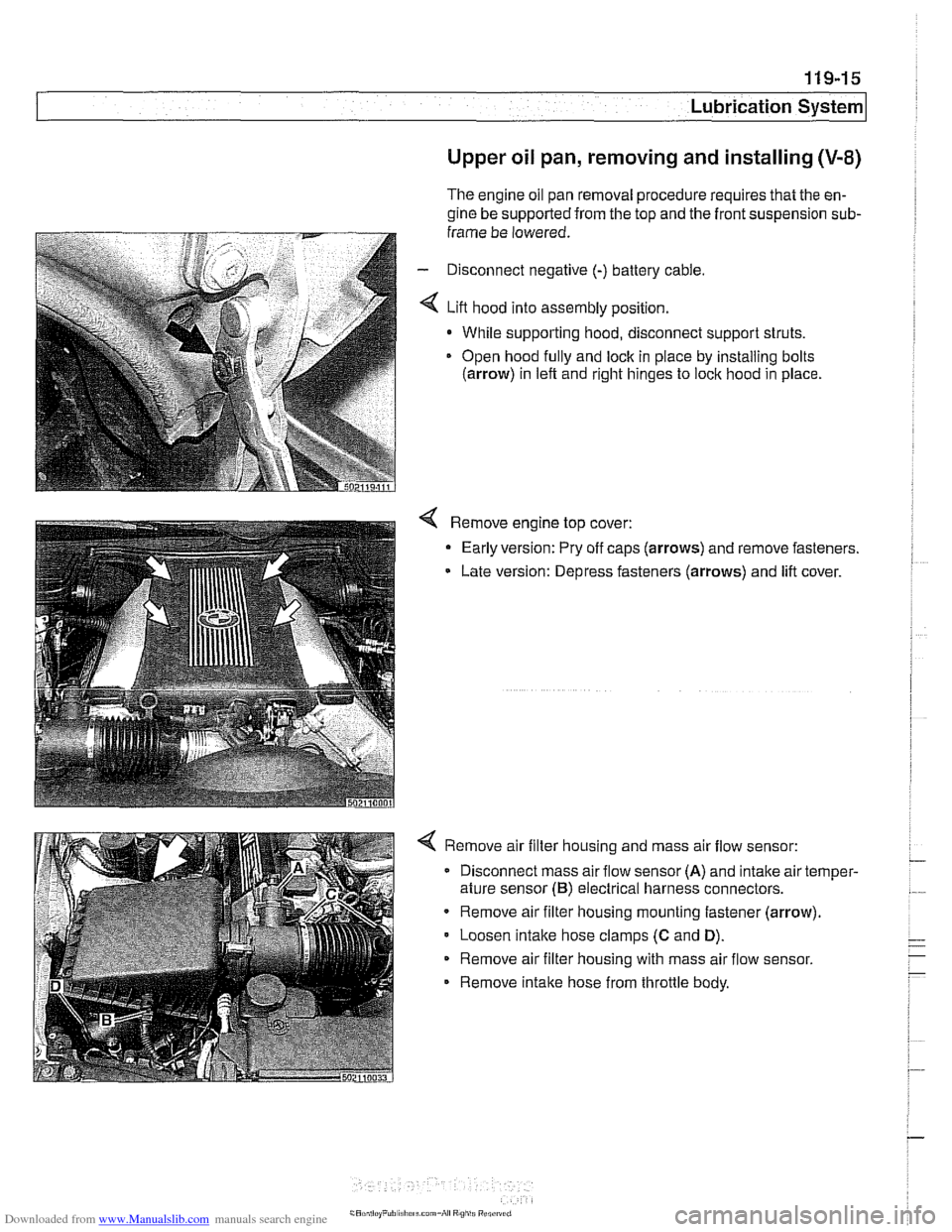
4 Lift hood into assembly position.
- While supporting hood, disconnect support struts.
Open hood
fully and lock in piace by installing bolts
(arrow) in left and right hinges to lock hood in place
4 Remove engine top cover:
- Early version: Pry off caps (arrows) and remove fasteners.
Late version: Depress fasteners (arrows) and lift cover.
4 Remove air filter housing and mass air flow sensor:
Disconnect mass air flow sensor
(A) and intake air temper-
ature sensor
(B) electrical harness connectors.
Remove air filter housing mounting fastener (arrow)
Loosen
intake hose clamps (C and D).
Remove air filter housing with mass air flow sensor.
Remove intake hose from throttle body.
Page 343 of 1002
Downloaded from www.Manualslib.com manuals search engine
Lubrication System
- Lower front suspension and remove oil pan, as described
earlier, to gain access to oil pump.
Remove oil pump
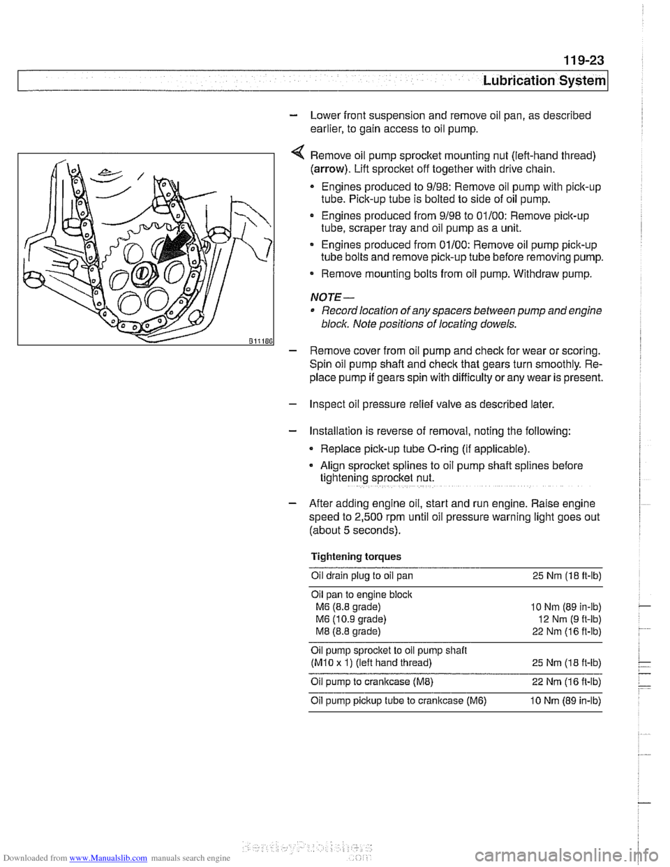
sprocket mounting nut (left-hand thread)
(arrow). Lift sprocket off together with drive chain.
Engines produced to 9/98: Remove oil pump with pick-up
tube. Pick-up tube is bolted to side of oil pump.
Engines produced from 9/98 to 01/00: Remove pick-up
tube, scraper tray and oil pump as a unit.
Engines produced from 01/00: Remove oil pump pick-up
tube bolts and remove pick-up tube before removing pump.
Remove mounting bolts from oil pump. Withdraw pump.
NOTE-
Record location of any spacers between pump and engine
bloclc Note positions of locating dowels.
- Remove cover from oil pump and check for wear or scoring.
Spin oil pump shaft and
check that gears turn smoothly. Re-
place pump if gears spin with difficulty
orany wear is present.
- Inspect oil pressure relief valve as described later.
- Installation is reverse of removal, noting the following:
Replace pick-up tube O-ring (if applicable).
- Align sprocket splines to oil pump shaft spl~nes before
tightening sprocket nut.
- After adding engine oil, start and run engine. Raise engine
speed to 2,500 rpm until oil pressure warning light goes out
(about 5 seconds).
Tightening torques Oil drain plug to oil pan 25
Nm (18 ft-lb)
Oil pan to engine
bloclc
M6 (8.8 grade)
M6 (10.9 grade)
M8 (8.8 grade)
10 Nm (89 in-lb)
12
Nrn (9 ft-lb)
22 Nm (16 ft-lb)
Oil pump sprocket to oil pump shait
(M10 x 1) (left hand thread)
25 Nm (1 8 it-lb)
Oil pump to crankcase (ME) 22 Nm (1 6 it-lb)
Oil pump pickup tube to cranltcase (M6) 10 Nm (89 in-lb)
Page 530 of 1002
Downloaded from www.Manualslib.com manuals search engine
- Removing left side exhaust manifolds (cylinder bank 5-8):
- Remove heat baffle plate on left side.
Remove oxygen sensor using
BMW special tool 11 7 030
or similar oxygen sensor socket.
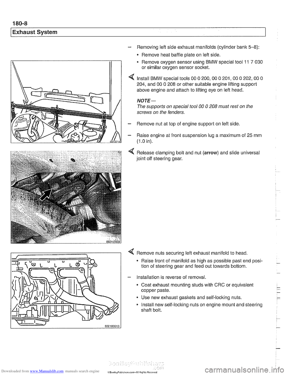
Install
BMW special tools 00 0 200,OO 0 201,OO 0 202,OO 0
204, and 00 0 208 or other suitable engine lifting support
above engine and attach to lifting eye on left head.
NOTE-
The supports on special tool 00 0 208 must rest on the
screws on the fenders.
- Remove nut at top of engine support on left side
- Raise engine at front suspension lug a maximum of 25 mm
(I
.O in).
Release clamping bolt and nut
(arrow) and slide universal
joint off steering gear.
4 Remove nuts securing left exhaust manifold to head,
Raise front of manifold as high as possible past end posi-
tion of steering gear and feed out towards bottom.
- Installation is reverse of removal.
Coat exhaust mounting studs with CRC or equivalent
copper paste.
Use new exhaust gaskets and self-locking nuts.
Install new self-locking nuts on engine mount and steering
shaft bolt.